J. of the Braz. Soc. of Mech. Sci. & Eng. Copyright 2006 by ABCM July-September 2006, Vol. XXVIII, No. 3 / 269
Anderson C. A. de Melo
Departamento de Pesquisa Instituto Superior Tupy Sociedade Educacional de Santa Catarina Rua Albano Schmidt, 3333 Boa Vista 89.227-700 Joinville, SC. Brazil anderson.melo@sociesc.com.br
Júlio César G. Milan
Departamento de Engenharia Mecânica – DEMCentro de Ciências Tecnológicas – CCT Universidade do Estado de Santa Catarina Campus Universitário Prof. Avelino Marcante s/n, Bom Retiro 89223-100 Joinville, SC. Brazil
Márcio B. da Silva
and Álisson R. Machado
Laboratório de Ensino e Pesquisa em Usinagem Faculdade de Engenharia Mecânica Universidade Federal de Uberlândia Av. João Naves de Ávila, 2121, Santa Mônica 38.400-100 Uberlândia, MG. BrazilSome Observations on Wear and
Damages in Cemented Carbide Tools
Cutting tools are subjected to extremely unfavorable conditions during machining operations. High cutting temperatures, compressive and shearing stresses, chemical attacks, variable cyclic thermal and mechanical loads are some adverse conditions that wear and damage these tools. Therefore, it is crucial to understand the process of tool wear and damage and how the cutting parameters affect it in order to underpin decisions regarding the most favorable conditions to address the problem. This article treats on some forms and mechanism of wear and damage that cemented carbides can undergo during machining. Special attention was given to damages caused during interrupted cutting (e.g., milling), such as fracture, chipping and thermal fatigue. Experimental details and results of the latter phenomenon, which was studied under different cutting conditions, are discussed and confronted with literature.
Keywords: Cemented carbide tools, milling, tool damage, thermal fatigue
Introduction
A distinction should be made, right from the start, between the phenomena of wear and damage. The classic definition of wear, regardless of the cause but here referring specifically to cutting tools, is: “the loss or dislocation of mass of a material caused by some kind of tribological phenomenon”. Wear on tools can appear in the form of a crater on the rake face, flank wear on the flank face or a notch that may appear at either the nose or the end of the cutting depth, normally on the flank face. In cemented carbide cutting tools these forms of wear can develop by one or a combination of the following wear mechanisms (Trent and Wright, 2000): plastic deformation under compressive stress, diffusion, attrition, abrasion and wear under slide conditions. These wear mechanisms lead to a continual loss or dislocation of material, which does not occur suddenly, but rather, develops over a long period of time. 1
Although tool damage also leads to mass loss or mass dislocation, unlike wear, it occurs suddenly and unexpectedly, usually involving a larger volume of tool mass. This damage can be characterized by “fracture”, “chipping” and “fatigue” of a mechanical origin, or by “thermal fatigue” caused by temperature fluctuations.
These forms of wear and damage are discussed below.
Wear and Mechanism of Wear on Cemented Carbide Tools
Figures 1 to 6 show the types of wear normally developed in cemented carbide cutting tools after machining.
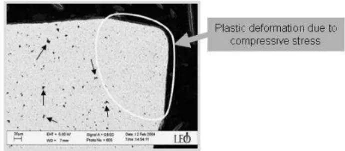
Figure 1 shows an example of plastic deformation under compressive stress obtained by Östberg et al. (2006). The cutting
Paper accepted June 2006. Technical Editor: Anselmo Eduardo Diniz.
edge of a WC-TaC-Co cemented carbide cutting tool after turning SS 2541 steel shows a strong evidence of plastic deformation. As can be seen the region of the cutting wedge affected by high compression stress during the cut presents absence of porosity, unlike the bulk region.
Figure 1. SEM micrograph of the deformed WC-TaC-Co cemented carbide. The image shows an overview of a cutting edge cross-section. The porosity (black spots, some pointed by arrows) seen in the bulk region is absent in the deformed region (Östberg et al., 2006).
Figure 2 shows an ISO K20 uncoated cemented carbide cutting tool after machining Ti-6Al-4V alloy. It can be observed a crater wear on the rake face very close to the cutting edge. According to Machado and Wallbank (1990) this characteristic is peculiar when machining titanium alloys.
Figure 2. Rake face wear overview of an ISO K20 cemented carbide cutting tool after machining Ti-6Al-4V (Machado, 1990).
A sequence of pictures in Fig. 3 shows evidences of attrition wear obtained by Machado (1990). In the specialized literature (Hutchings, 1992 and König and Klocke, 1997), attrition is frequently treated as adhesion. Who first introduced the term “attrition” was Edward Trent. This wear mechanism generally occurs under low cutting speeds, due to the irregular flow of chip material on the rake face and it is very common when built-up-edge (BUE) is present. Attrition consists basically in: (1) adhesion of workpiece material on the cutting tool surfaces; (2) breakaway of microscopic particles of the cutting tool material and (3) dragging of these particles on cutting tool surfaces, generally causing abrasion.
Figure 3(a) shows a typical notch wear on the flank face of an ISO K20 cemented carbide cutting tool after machining Inconel 901 with a layer of workpiece material adhered on this region. On section A-A [Fig. 3(b)] it is possible to observe a layer of workpiece material adhered during machining on the notch region of the flank face. Figure 3(c) shows a magnification of tool-adhered layer interface. It is observed a large crack running parallel to the flank face, which appeared during metallographic sample preparation. What is most important in this figure is the evidence of the carbide grains that were detached from the flank face of the cutting tool flowing within the work material layer (adhered layer). This is what Trent and Wright (2000) call attrition.
Figure 3. Sequence of pictures showing evidence of attrition wear on a notch wear region of an ISO K20 cemented carbide cutting tool after machining Inconel 901 (Machado, 1990).
Figure 4(a) shows a huge BUE formed after machining an aluminum alloy under low cutting speed obtained by List et al. (2005). According to the authors this condition is characterized by the combination of lowest temperatures and highest pressures at the tool-chip interface, which leads to adhesion by interlocking of the rake face asperities of the WC grains as showed in figure 4(b). In this situation, if the presence of BUE on the rake face is instable, it
can draw out small particles of the cutting tool causing attrition and consequently progressive wear of the cutting tool.
Figure 4. SEM images of a polished uncoated WC-Co cutting tool section after machining an aluminum alloy during 7min; vc=60m/min and f=0.1mm/rev. (List et al., 2005).
Figure 5 shows an example of abrasion wear on the flank face of a WC+Co cemented carbide cutting tool coated with TiCN+Al2O3+TiN after simultaneously boring two distinct
materials. In this case, when machining bimetallic bearings composed by GH190 lamellar gray cast iron and Fe-C-Cu steel alloy (Corrêa et al., 2005). It can be noticed the presence of some parallel grooves formed by flow of the workpiece material during machining. According to the authors abrasion occurred only when machining the bearing’s half composed by GH190 gray cast iron.
Abrasion wear on cutting tools happens when tool material is removed or dislocated by hard particles that can be loose, between chip and rake face, or emerging from workpiece material and/or from cutting tool material (Machado and da Silva, 2004).
Figure 5. Evidence of abrasion on a cemented carbide tool (Corrêa et al., 2005).
Figure 6 shows an example of a notch wear occurred on flank face of a K20 cemented carbide cutting tool after machining Inconel 901 (Machado, 1990). It can be seen evidences of attrition in the notch. Notch wear is a type of wear and not properly a mechanism of wear. However, there is no consensus in the literature explaining the mechanism that causes this type of wear (Machado and da Silva, 2004).
Notch wear occurs mainly when machining materials with poor thermal properties such as nickel alloys, titanium, cobalt and stainless steel and it can develop either on the flank face and on the rake face of a cutting tool. According to Trent and Wright (2000), this type of wear generally occurs in regions where sliding condition persists and involves abrasion and attrition and suffers strong influence of the atmosphere, mainly due to the amount of oxygen.
J. of the Braz. Soc. of Mech. Sci. & Eng. Copyright 2006 by ABCM July-September 2006, Vol. XXVIII, No. 3 / 271
The following section treats on damages in cemented carbide tools.
Damages in Cemented Carbide Tools
Mechanical Fracture and Chipping
Fracture and chipping are deterioration processes that frequently cause breakage before a significant wear on the tool surfaces (Trent and Wright, 2000). In continuous cutting, it is rare to observe fracture or chipping on a tool edge, as in a turning operation. Fracture of cemented carbide tools is more likely to occur during interrupted cutting, as in milling operations. Under these conditions, the cutting edge can be damaged due to cyclic mechanical impacts or fatigue. Tool characteristics such as hardness, fracture toughness, transverse rupture strength (TRS), grain size, tool geometries, cutting parameters and conditions of entrance and exit into and from the workpiece are all important variables for tool damage prevention.
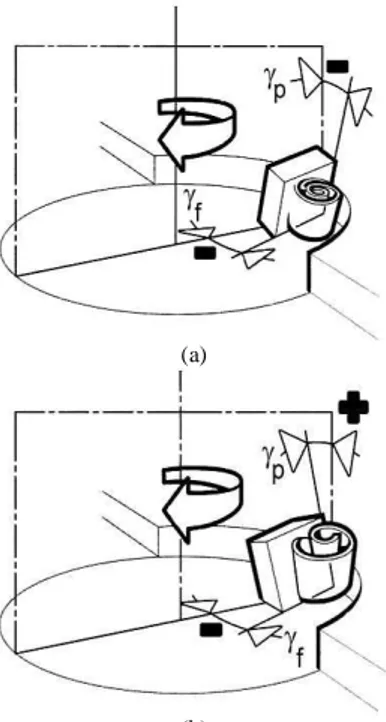
When milling hard materials, or in the presence of intense mechanical impacts during machining, a double negative tool geometry [negative axial (γp) and radial (γf) rake angles] is
recommended, although a positive-negative tool geometry [positive axial (γp) and negative radial (γf) rake angles] can also perform well.
With these tool geometries, the cutting wedges possess higher strength to cope with the adversities of inherent mechanical shocks (Anonymous, 1994). These angles are illustrated in Fig. 7.
(a)
(b)
Figure 7. Tool geometries recommended when milling hard materials: (a) negative tool geometry and (b) positive-negative tool geometry (Anonymous, 1994).
Still with regard to milling, the main cutting parameter that affects tool chipping or fracture is known to be the feed rate. Increasing the feed rate causes proportional increases in the undeformed chip thickness, thereby increasing the primary and secondary shear plane areas and leading to higher cutting forces.
In milling, mechanical fracture or chipping of cutting tools can be caused by problems at the tool’s entrance into or exit from the workpiece. According to Machado and da Silva (2004) and
Kabaldin (1980), the chips of some work materials, such as titanium and stainless steel, tend to stick and gall onto the tool’s rake faces just before the tool teeth exit the workpiece, where they get stuck during the idle moments in a milling cutter revolution. When the tool’s teeth reenter the workpiece upon resumption of the cutting cycle, the chips can cause edge chipping in the tools. Figure 8 shows a phenomenon like this when turning Ti-6Al-4V with cemented carbide. It can be observed the strong adhesion of the chip and workpiece materials on the cutting edge.
Figure 8. Adhesion of Ti-6Al-4V on cutting edge of the cemented carbide after turning (adapted from Ribeiro et al., 2003).
The extent of tool damage depends on the various aforementioned parameters (tool resistance and geometry, cutting conditions, etc).
According to Pekelharing (1978), excessive tool chipping can also occur when the tool’s teeth are exiting the workpiece. This author observed the behavior of the primary shear plane that rotates and becomes negative as the tool exits the workpiece. The ultimate result of this process is the formation of what the author called foot forming, because the chip thus formed resembles a human foot. The negative shear resulting from the primary shear plane rotation causes the chip velocity to become negative, producing tensile stress on the rake face of the tool tip, which, in turn, is responsible for ploughing off small quantities of material from the tool’s surface, causing fracture or chipping. Figure 9, illustrates the foot forming phenomenon.
a) In diagram A of Fig. 9, the tool edge is about 0.9mm from emerging out of the trailing edge of the workpiece. The negative shear begins here, although the positive shear zone is still visible. The foot follows the direction of the negative shear and a rotation of the plane with an angle of -9o is
visible. The chip rests in a chip-tool contact length of approximately 3h with null rotation.
b) In diagram B, the tool edge is only 0.48mm from the trailing edge of the workpiece. The negative primary shear plane shrinks, now with even greater rotation, showing an angle of -27o with the chip showing a slight rotation of 8o, as well. The chip-tool contact length is reduced to approximately 1h. Note, also, that the shear at the positive shear plane has expired, working only as a connection between the foot and the rigid part of the chip, or “the leg”. A crack may begin to develop at the lower end of the negative shear plane. c) In diagram C, the tool edge is now 0.36mm from the trailing
edge of the workpiece. The negative shear plane becomes thinner, curving even further towards the left. Now the inclination angle of this plane is -33o and the chip has
rotated to an angle of 14o. The crack in this shear plane has increased at this stage.
workpiece, while the foot and leg are already free of the workpiece. This situation occurs because the crack has progressed throughout the entire negative shear plane. At this moment, the angle of this plane is -35oand the chip-tool contact length is only approximately 1/3h, with the chip rotating at an angle of 16o.
Figure 9. Sequence of the phenomenon of foot forming according to Pekelharing (1978).
The negative shear caused by the rotation of the primary shear plane promotes a negative chip velocity, briefly producing tensile stress along the chip-tool contact length. This process happens very quickly, so that the tool, which a moment earlier was undergoing a highly compressive stress, is now under tensile stress. This change can cause breakage of the tool tip if it is not sufficiently tough. This type of failure can be prevented by chamfering the trailing edge of the workpiece or by establishing a tool exit angle, ε, of more than 20o or less than -45o, as illustrated in Fig. 10. With these cutting geometries, the undeformed chip thickness is small enough to prevent tool damage.
Figure 10. Safe tool exit angles (Anonymous, 1994).
Thermal and Mechanical Fatigue
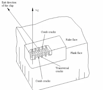
Thermal fatigue in cemented carbide tools occurs frequently in interrupted cutting such as milling operations. Thermal fatigue in cutting tools is evidenced by the development of cracks running along the rake and flank faces perpendicularly to the cutting edge, as illustrated in Fig. 11.
Figure 11. Thermal cracks in a cemented carbide tool (Melo, 2001).
Trent and Wright (2000) explain that these cracks are promoted by the cyclic expansion and contraction of surface layers of cutting tools when they are cyclically heated and cooled during cutting processes. Figure 12 depicts the thermal cycle that a tool experiences during continuous and interrupted cutting. Curve a represents the heat that builds up in continuous cutting, in which the temperature tends to stabilize at a certain value. In practice, this value increases with wear. Curve b represents the continuous cooling of the tool from the cutting temperature down to room temperature.
J. of the Braz. Soc. of Mech. Sci. & Eng. Copyright 2006 by ABCM July-September 2006, Vol. XXVIII, No. 3 / 273
period starts at that point and lasts for a given time, t2, during which the tool cools, reaching temperature T’1 at the end of time t1 + t2. At that point, the tool resumes cutting and the cycle is repeated in each revolution of the milling tool.
The specialized literature (Trent and Wright, 2000; Pekelharing, 1978; Ferraresi, 1977; Melo, 2001) reports that thermal cracking occurs in tools used for interrupted cutting as a result of cyclic variations in temperature. The T1 and T’1 temperatures are, of course, dependent on the t1 and t2 times, as well as on the cutting parameters (cutting speed, feed rate and cutting depth), on the workpiece and tool materials, on the cutting geometry, and on the presence or absence of a cutting fluid. Thus, the relation between cutting and idle periods is a crucial factor in the process of crack formation and the development of thermal fatigue.
Figure 12. Cyclical variation of the cutting temperature in an interrupted cutting process (adapted from Palmai, 1987).
The phenomenon is explained by Ferraresi (1977) as follows: “Figure 13(a) presents a temperature distribution curve along depth x which varies from the rake face down towards the tool’s bottom surface. During the heating (cutting) period, due to the intense shear involved in the flow zone, the external layer of the tool is subjected to very high temperatures, which cause it to expand. However, subjacent layers, whose temperatures are lower, are subjected to less expansion. As a result, the innermost layers hinder the total expansion of the outermost layer, giving rise to compressive stresses in the latter and tensile stresses in the former, Fig. 13(b). The moment the tool tip exits the workpiece, i.e., at the beginning of the idle period, the tool begins to cool from the outermost layer inwards, as depicted in Fig. 13(c), causing an inversion of the stresses in these layers, Fig. 13(d)”.
Figure 13. Temperature and stress distribution during cutting and idle periods incemented carbide inserts of a milling cutter (Ferraresi, 1977).
These temperature fluctuations are more common in interrupted cutting, but they can also occur in response to frequently irregular access of cutting fluid at the chip/tool interface in continuous cutting, caused, for example, by the formation of a nest of swarf. After a certain number of cycles, thermal cracks appear on the tool surface (see Fig.11), subsequently transforming into comb cracks, as shown schematically in Fig. 14, if the cut continues.
Figure 14. Comb cracks (Ferraresi, 1977).
Variations in temperature (∆∆∆∆T=T1-T’1) cause variations in stress on the tool surface, and are therefore a determining factor of cracking. Thermal cracks normally initiate at the hottest point of the chip/tool interface (about 0.1 to 0.3mm from the cutting edge) and propagate towards the cutting edge and the flank surface. These thermal cracks therefore run perpendicularly to the cutting edge. They may occasionally encounter mechanical cracks running parallel to the cutting edge, which can lead to chipping and/or spalling at the tool surface, drastically reducing the tool’s life. Figure 15 illustrates this phenomenon.
Ferraresi (1977) presented thermal crack results obtained by Lehewald (1963) after testing P10, P20, P25, P30 and P40 grade cemented carbide tools in the face milling of AISI 1045 steel. Figure 16 shows the ultimate thermal crack curves for each tool grade as a function of the feed per tooth and the number of cuts (number of milling cutter tool revolutions).
Figure 16. Ultimate thermal crack curves for face milling AISI 1045 steel with various grades of cemented carbide tools; vc=148m/min; doc=5mm, after Lehewald (1963), cited by Ferraresi (1977).
As can be seen, the number of cuts required for the first crack to appear decrease as the feed per tooth increases. Such diagrams are particularly useful for adjusting cutting parameters when machining a certain tool/workpiece pair, because they enable one to select a feed per tooth ratio that precludes thermal cracking. Figure 16 also shows that P10 and P20 tool grades are less resistant to thermal crack formation.
The number of thermal cracks generated on a tool surface is limited (Ekemar et al., 1970), and was dubbed “thermal crack limit number” by Ferraresi (1977). Figure 17 presents the behavior of various cemented carbide tool grades after tests conducted by Lehewald (1963) and also reported by Ferraresi (1977). The graph in Fig. 17 shows the number of thermal cracks as a function of the number of cuts (number of milling cutter revolutions). The number of thermal cracks begins by growing exponentially, after which it stabilizes at the limit number. The greater the toughness the lower the thermal crack limit number.
Figure 17. Number of thermal cracks versus number of cuts for several cemented carbide tool grades; work material: AISI 1045 steel; vc=170m/min; fzxdoc=0.25x5mm2, after Lehewald (1963), cited by Ferraresi (1977).
Figure 18 shows how the feed per tooth affects the thermal crack limit number, according to Lehewald (1963). Note that a higher feed per tooth ratio leads to a lower thermal crack limit number. The
author explains that higher average cutting temperatures develop at higher feed rates or higher undeformed chip thickness than at lower feed rates. The result is a lower percentage reduction in tool temperature during the idle period, which leads to a reduction in the number of thermal cracks. These findings, however, disagree with those of Bhatia et al. (1979), who observed an increase in ∆T when the feed rate was increased during interrupted cutting.
Figure 18. Number of thermal cracks along the cutting length per tooth after face milling AISI 1045 steel with P25 cemented carbide for several feed rates per tooth; vc=170m/min; doc=5mm, after Lehewald (1963), cited by Ferraresi (1977).
Melo (2001) also found a slight increase in the number of thermal cracks at higher feed rates, corroborating Bhatia et al.’s findings, as shown in Fig 19. This is particularly evident when increasing the feed per tooth from 0.10mm to 0.15mm for a 500mm cutting length and from 0.20mm to 0.25mm for a 1000mm cutting length.
Figure 19. Average density of thermal cracks (number of thermal cracks/cutting edge active length) as a function of the feed rate for uncoated P25 cemented carbide tools after machining AISI 1045 steel through 500, 1000, and 1500mm of cutting length; vc=240m/min; doc=2.0mm (Melo, 2001).
Melo (2001) explains that thermal stresses generated at the cutting edges of the tools are more severe when higher feed rates are used due to the increase of the temperature ∆T. An explanation for cases where an increase in feed rate did not conspicuously increase the number of thermal cracks is that an increase in the feed rate increases ∆T (Bhatia et al., 1979) but also reduces the number of thermo-mechanical cycles (number of idle and cutting periods) for the same cutting length, thus reducing the risk of thermal cracking. Thus, the system must be evaluated considering both these effects. When they are evenly balanced, the density of thermal cracks remains practically unchanged, but when an increase in ∆T prevails, the density of thermal cracks increases.
J. of the Braz. Soc. of Mech. Sci. & Eng. Copyright 2006 by ABCM July-September 2006, Vol. XXVIII, No. 3 / 275
limit number, as shown in Fig. 20. This is entirely congruous with Melo’s findings shown in Fig. 21.
This figure shows that even after the third pass (cutting length of 1500mm), a cutting speed of 100m/min was unable to produce sufficiently high temperature variations (∆T) to cause thermal cracking. Another fact that may corroborate the absence of thermal cracking at this cutting speed is the number of thermo-mechanical cycles, which may not suffice to promote the thermal fatigue necessary to cause cracking. Possibly, with additional passes, the cracks might begin to nucleate and propagate on the tool faces. However, this possibility would have to be confirmed through further tests.
Figure 20. Influence of the cutting speed on the thermal cracks formed during milling of AISI 1045 steel with P25 cemented carbide tools, fz=0.25mm/tooth; doc=5mm, after Lehewald (1963), cited by Ferraresi (1977).
Figure 21. Average density of thermal cracks (number of thermal cracks/cutting edge active length) as a function of the cutting speed for uncoated P25 cemented carbide tools after milling AISI 1045 steel through 500, 1000, and 1500mm of cutting length; fz=0.15 mm/tooth; doc=2.0 mm (Melo, 2001).
Increasing the cutting speed to 170m/min, 240m/min and 310m/min clearly also increases the density of thermal cracks, although the change from 240 to 310m/min is statistically inaccurate because there is overlapping of standard deviations. Probably at such high cutting speeds, the thermal crack limit number of Lehewald (1963) is reached earlier, and the number seems to vary only slightly, which may explain these results.
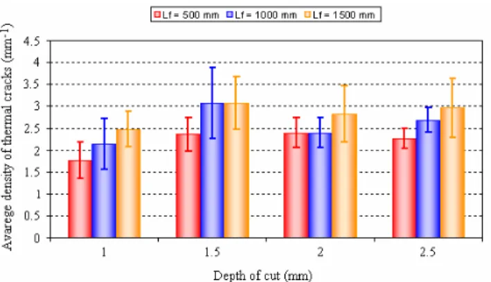
The influence of the axial depth of cut was also studied by Melo (2001), whose results are illustrated in Fig. 22.
Only slight variations in the average thermal crack density were visible within the range of depths of cut investigated (1.0 to 2.5 mm). The author attributes this result to the fact that a small depth of cut requires low cutting power, since the cutting area is small.
Consequently, the temperature developed during the cutting period is low and is also distributed in a smaller area of the tool. In contrast, large depths of cut require high cutting power, generating large quantities of heat and developing high cutting temperatures, which are distributed in a larger tool area. Practical results of these two situations indicate that only slight differences in tool temperatures occur during cutting periods. The temperature during the idle period can be similarly analyzed. With small depths of cut, an equally small area of the tool exchanges heat with the ambient air, while high depths of cut cause a larger area of the tool to exchange heat with the air. Thus, it is reasonable to assume that the difference between the maximum and minimum temperatures during each cutting cycle will not vary significantly with changes in the depth of cut. As a result, there will be no significant alterations in the thermal stresses and, hence, in the densities of thermal cracks resulting from variation in the depth of cut.
Figure 22. Average density of thermal cracks (number of thermal cracks/cutting edge active length) as a function of the axial cutting depth for uncoated P25 cemented carbide tools after face milling AISI 1045 steel through 500, 1000, and 1500mm of cutting length; fz=0.15mm/tooth; vc=240m/min (Melo, 2001).
This phenomenon can also be expressed by the equation that represents the energy consumed per unit of chip area produced:Fc b=ks.h, where Fc is the cutting force; b is the
undeformed chip width (which is a function of the depth of cut); ks
is the constant specific cutting force and h is the undeformed chip thickness. If the feed per tooth is kept constant, the product ks.h is
also constant, and so is Fc/b. Therefore, a change in the cutting
depth (or in the undeformed chip width) is not expected to cause variations in the density of thermal cracks.
Another important parameter, which strongly influences the formation of thermal cracks is the radial cutting depth, or the cutting width, ae. Melo (2001) investigated this variable as well, using three
different ae values (30, 55 and 80mm), as shown in Fig. 23.
Figure 23. Relative positions of the milling cutter for cutting at a radial cutting depth of 30, 55 and 80 mm (Melo, 2001).
Figure 24. Average density of thermal cracks (number of thermal cracks/cutting edge active length) as a function of the radial cutting depth for uncoated P40 cemented carbide tools after face milling AISI 1045 steel through 500mm of cutting length; doc=2.0mm; fz=0.15mm/tooth; vc=240m/min (Melo, 2001).
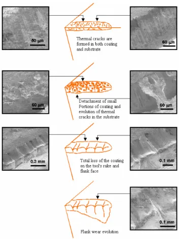
The cutting fluid is another agent that strongly influences the process of thermal crack formation. The use of a cutting fluid in milling processes may be highly detrimental to the tool’s life, depending on the cutting parameters, tool material and the type of damage involved. In the presence of thermal cracks, the cutting fluid will accelerate their nucleation process and reduce the tool’s life regardless of the type of cutting fluid used (Vieira et al., 2001). In his investigation, Melo (2001) also took into account the application of cutting fluids. He demonstrated that using a flood of cutting fluid during the milling process caused the thermal crack tool damage to rapidly trash the tool, while cutting without fluid, in the dry mode, delayed the formation of thermal cracks and prolonged the tool’s life. Figure 25 contains a sequence of photos showing the rapid evolution of wear on an ISO P45 cemented carbide tool coated with TiN + TiCN during the face milling of an AISI 1045 steel with the flood application of a cutting fluid. As can be seen, the cutting fluid accelerates the formation of thermal cracks in both coating and substrate, exposing the tool to other negative effects of the milling process and rapidly ending its useful life. This figure depicts the following stages:
i) Formation of multiple cracks in the coating and several in the substrate;
ii) The cracks formed in the coating join, causing partial detachment of the coating and exposing small regions of the substrate, leading to the development of a comb crack formation pattern;
iii) Total loss of the coating on the tool’s rake face; iv) Evolution of flank wear.
Figure 25. Different stages of thermal crack formation and wear evolution of ISO P45-coated tools during face milling of AISI 1045 steel with flood application of a cutting fluid (Melo, 2001).
During interrupted cutting as in milling, other cracks of mechanical origin, besides thermal cracks that run perpendicular to the cutting edge, may appear and run parallel to the cutting edge. These are cracks developed by mechanical fatigue in the way already explained. Figure 26 shows an example of mechanical cracks (white arrows) and thermal cracks (black arrows) running on an ISO P25 cemented carbide tool’s surface. Many of them will appear transversally at the ridges formed on a tool with comb cracks.
J. of the Braz. Soc. of Mech. Sci. & Eng. Copyright 2006 by ABCM July-September 2006, Vol. XXVIII, No. 3 / 277
These transversal cracks are attributed to fluctuations in the mechanical loads acting on the cutting wedge, which is common in such interrupted processes. Constant shear loading and unloading on the rake and flank surfaces of the tools at every rotation of the tool causes mechanical fatigue and nucleation of cracks running transversally to the chip flow on the tool’s rake face parallel to the cutting edge. If the tool/workpiece contact area is large enough due to flank wear, a tribological situation similar to that of the rake face will occur, and mechanical fatigue will also occur on the tool’s flank face, as indicated in Fig. 27.
Figure 27. Detail of mechanical cracks developed on the flank face parallel to the cutting edge of an uncoated ISO P25 cemented carbide tool after milling AISI 1045 steel (Melo, 2001).
Final Considerations
From those information and discussion presented in this paper, it can be concluded that wear is unavoidable. However, in the presence of cracks from either mechanical or thermal origins wear may be left in a second level. Such cracks are unexpected damages that occur more commonly during interrupted cutting (e.g., milling processes), in which the tool constantly undergoes very repetitive mechanical shocks and significant thermal variations imposed by the characteristics of the process. Under such circumstances the tool’s material is one of the most important variables. Today, the market offers high performance micrograin (less than 1 m) cemented carbide and other types of tools, which combine several good physical and mechanical properties to help overcome the problem of interrupted cutting. It should be pointed out that the use of cutting fluids in such processes, particularly water-based fluids, is extremely detrimental to the tool’s service life, for these fluids augment temperature fluctuations, ∆T, and accelerate the mechanism of thermal crack formation. Therefore, before using a cutting fluid in an interrupted cutting process, a detailed analysis of the pros and cons is vital to the success of the manufacturing process.
References
Anonymous, 1994, “Modern Metal Cutting – A Pratical Handbook”,
Sandvik Coromant Ltda, First edition.
Bhatia, S. M., Pandey, P. C. and Shan, H. S., 1979, “Failure of Cemented Carbide Tools in Intermittent Cutting”, Precision Engineering, pp 148-152.
Corrêa, D. C., Sales, W. F., Santos, S. C. and Palma, E. S., 2005, “Machinability of Bimetallic Bearings using Cemented Carbide Tools: Evaluation of the Wear Mechanisms”, Journal of Materials Processing
Technology 159, 435-444.
Ekemar, C. S. G., Iggström, S. A. O. and Héden, G. K. A., 1970, “Influence of Some Metallurgical Parameters of Cemented Carbide on the Sensitivity to Thermal Fatigue Cracking at Cutting Edges”, Materials for
Metal Cutting, Proc. Conf. of BIRSA, Scarborough, 14-16 April.
Ferraresi, D., 1977, “Fundamentos da Usinagem dos Metais” (Fundamentals of Metal Cutting), vol. 1, Editora Edgard Blücher Ltda [In Portuguese], 751 pages.
Hutchings, I.M., 1992, “Tribology – Friction and Wear of Engineering Materials” Published by Edward Arnold, London, ISBN 0 340 56184 X, 273 pgs.
Kabaldin, Y. G., “Temperature and Adhesion in Continuous and Interrupted Machining”, Machines and Tooling, vol. 51, no 4, pp. 33-36.
König, W. und Klocke, F., 1997, “Fertigungsverfahren: Drehen, Fräsen und Bohren”, Springer-Verlag, Berlim – Heidelberg, 5 Auflage, Band 1, 471 pgs.
Lehewald, W., 1963, “Untersuchungen über die Entstehung von Rissen und Schneidausbrüchen beim Stirnfräsen von Stahl mit Hartmetall“,
Industrie-Anzeiger, Essen (46), pp. 981-988.
List, G., Nouari, M., G´ehin, D., Gomez, S., Manaud, J. P., Le Petitcorps, Y., Girot, F., 2005, “Wear Behaviour of Cemented Carbide Tools in Dry Machining of Aluminium Alloy”, Wear 259, 1177–1189.
Machado, A. R. and da Silva, M. B., 2004, “Usinagem dos Metais” (Metal Cutting), Technical Notes, 9th version, [In Portuguese], 257 pages.
Machado, A.R., 1991, “Condições da Interface Cavaco-Ferramenta. Parte I: Generalidades”, XI COBEM 11 a 13 de dezembro, São Paulo SP, pp. 381-84.
Machado, A.R., 1990, “Machining of Ti6Al4V and Inconel 901 with a High Pressure Coolant System”, PhD Thesis, University of Warwick, Coventry, England, September, 288 pgs.
Machado, A.R. and Wallbank, J., 1990, "Machining of Titanium and Its Alloys - A Review", Proc. of the Inst. Mech. Eng. Vol 204 Part B , J. Eng.
Manufacture,I IMECHE, London, England, pp. 53-60.
Melo, A. C. A., 2001, “Estudo das Trincas de Origem Térmica Geradas em Ferramentas de Metal Duro Durante o Fresamento Frontal” (Study on Thermal Cracks Generated in Cemented Carbide Tools During Face Milling), PhD thesis, Universidade Federal de Uberlândia, Uberlândia – MG, 173 pgs [In Portuguese].
Palmai, Z., 1987, “Cutting Temperature in Intermittent Cutting”,
International Journal of Machine Tools and Manufacture, vol. 27(2), pp.
261-274.
Östberg, G., Buss, K., Christensen, M., Norgren, S., Andrén, H. O., Mari, D., Wahnström and Reineck, I., 2006, “Effect of TaC on Plastic Deformation of WC-Co and Ti(C, N) – WC – Co”, International Journal of
Refractory Metals & Hard Material, 24, 145-154.
Pekelharing, A. J., 1978, “The Exit Failure in Interrupted Cutting”,
Annal of CIRP, vol. 27, n.1, pp. 5-10.
Ribeiro, M. V., Moreira, M. R. V and Ferreira, J. R., 2003, “Optimization of Titanium Alloy (6Al-4V) Machining”, Journal of Materials
Processing Technology, 143-144, 458-463.
Trent, E. M., Wright, P. K., 2000, “Metal Cutting”, Butterworth/Heinemann, Oxford, 446 pages.
Vieira, J. M., Machado, A. R. and Ezugwu, E. O., 2001, “Performance of Cutting Fluids During Face Milling of Steels”, Journal of Materials