UNIVERSIDADE DE TRÁS-OS-MONTES E ALTO DOURO
COMPUTER VISION TO ASSIST VISUALLY IMPAIRED PEOPLE’S
NAVIGATION
Paulo Manuel Almeida Costa
A thesis submitted for the degree of Doctor in Computing Science
Supervisor: João Manuel Pereira Barroso Co-supervisor: Leontios Hadjileontiadis
[ iii ]
UNIVERSIDADE DE TRÁS-OS-MONTES E ALTO DOURO
COMPUTER VISION TO ASSIST VISUALLY IMPAIRED PEOPLE’S
NAVIGATION
Paulo Manuel Almeida Costa
University of Trás-os-Montes e Alto Douro School of Science and Technology
A thesis submitted for the degree of Doctor in Computing Science
Supervisor: João Manuel Pereira Barroso Co-supervisor: Leontios Hadjileontiadis
[ v ]
COMPUTER VISION TO ASSIST VISUALLY IMPAIRED PEOPLE’S
NAVIGATION
This work is presented by Paulo Manuel Almeida Costa to Universidade de Trás-os-Montes e Alto Douro for compliance with the requirements for obtaining a degree of Philosophiæ-Doctor (PhD) in Computer Science, under the supervision of Professor João Barroso of University of Trás-os-Montes e Alto Douro and Professor Leontios Hadjileontiadis of Aristotle University of Thessaloniki.
[ vii ]
D
OCTORAL
C
OMMITEE
President
Professor Doutor Manuel José Cabral dos Santos Reis
Professor Associado com Agregação da Universidade de Trás-os-Montes e Alto Douro
Members
Professor Doutor Vítor Manuel de Jesus Filipe
Professor Associado com Agregação da Escola de Ciências e Tecnologia da Universidade de Trás-os-Montes e Alto Douro
Professor Doutor João Miguel Fernandes Rodrigues
Professor Adjunto do Instituto Superior de Engenharia da Universidade do Algarve
Professor Doutor Armando José Formoso de Pinho
Professor Associado com Agregação da Universidade de Aveiro
Professor Doutor António Manuel de Jesus Pereira
Professor Coordenador da Escola Superior de Tecnologia e Gestão do Instituto Politécnico de Leiria
Professor Doutor João Manuel Pereira Barroso
Professor Associado com Agregação da Escola de Ciências e Tecnologia da Universidade de Trás-os-Montes e Alto Douro
[ ix ]
[ xi ]
A
CKNOWLEDGMENTS
Writing a doctoral thesis is an arduous process, long term and without the contribution and support of several people and institutions, this would not be possible. For this reason, I would like to express my gratefulness.
First of all, I would like to thank my scientific advisor João Barroso and co-advisor Leontios Hadjileontiadis for their constant support, fruitful discussions, exigence, patience and encouragement. To João, a special thanks for the opportunity to work in the area, for accepting me to work with him, for his vision and guidance, which permitted to successfully carry out the work herein presented. To Leontios, a special thanks for his indispensable help namely on revising all the documents and for his suggestions.
I also want to thank University of Trás-os-Montes e Alto Douro (UTAD) and Polytechnic Institute of Leiria, where I work as a lecturer, for the opportunity to engage in the PhD program and for all the logistic and support that I needed to carry out the work presented in this thesis. Additionally, I also would like to thank Instituto Politécnico de Leiria / Escola Superior de Tecnologia e Gestão for relieving my teaching duties, without which this research work would not have been possible in due time.
I also want to thanks to the department coordinators for their understanding and enabling the flexibility that permitted me to combine academic activities with research work. Thanks also to my department colleagues for the encouragement, availability and above all for friendship. Finally, I would like to express my special thanks to my family, especially to Sonia, Carolina and Laura, for often understanding my absence.
[ xiii ]
A
BSTRACT
Navigation is a major problem for people with visual disabilities and is one of the main challenges that researchers are still facing around the world. Over the last years a number of electronic travel aids (ETAs) have been developed with the aim of improving mobility of the visually impaired people. Despite several research efforts, these systems are rarely used, and the explanation is likely to be incomplete, but it is possible to identify three important factors: (1) positioning accuracy provided by these devices is not sufficient to guide securely the visually impaired thought a vast of environments; (2) the guidance methods should be adapted to the task of the visually impaired wayfinding; (3) this leads to the confidence and usability factor generated by the navigation systems. All these three factors are sources of usability issues. Even with the use of some of the electronic assistive technologies that exist nowadays, visually impaired may often suffer from disorientation or lack of accuracy of the mental map estimation of their location while walking in unknown environments.
In this doctoral thesis the main research work is to present and validate a model to assist visually impaired navigation. The proposed model uses computer vision techniques to extract accurately the blind users position from fiducial marks placed in the ground, validate its location and safely guide the blind user through their estimated route. The proposed model is to be part of a wearable system which must be reliable, portable and operate in real time. The proposed solutions aims to introduce improvements in the used computer vision techniques and in its application for features extraction to correctly estimate the blind user location. This thesis thus, contributes to the validation of an architecture model for blind user guidance system based on computer vision information that was validated with several tests in different real scenarios.
Key Words: Assistive Technologies, Navigation Systems, Visually Impaired, Computer
[ xv ]
R
ESUMO
A navegação é um dos principais problemas para as pessoas com deficiências visuais e é um dos principais desafios que os investigadores ainda enfrentam por todo o mundo. Ao longo dos últimos anos, um vasto conjunto de dispositivos eletrónicos de auxílio foram desenvolvidos com o objetivo de melhorar a mobilidade das pessoas com deficiência visual. Apesar das várias soluções, estes sistemas raramente são utilizados, sendo que, provavelmente será devido a um conjunto de três fatores importantes: (1) a informação de posição fornecida por estes dispositivos não é suficiente precisa para orientar de forma segura o deficiente visual em vários ambientes heterogéneos; (2) os métodos de orientação devem ser adaptados à tarefa de navegação do deficiente visual; (3) isto influencia o fator de confiança e usabilidade fornecido pelos sistemas de navegação. Mesmo com o uso das tecnologias de auxílio eletrónicas que existem nos dias atuais, os deficientes visuais podem sofrer desorientação ou falta de precisão na construção dos mapas mentais da sua localização ao caminhar em ambientes desconhecidos. Nesta tese de doutoramento, o principal objetivo de investigação é a apresentação e validação de um modelo para auxílio à navegação para pessoas com deficiência visual. O modelo proposto utiliza técnicas de visão por computador para extrair com precisão, a informação de posição a partir do reconhecimento de marcas fiduciárias colocadas nos passeios, validar sua localização e orientar com segurança o deficiente visual através da rota estimada. O modelo proposto integra uma parte de um sistema portátil que deve ser confiável e operar em tempo real. As soluções propostas visam introduzir melhorias nas técnicas de visão computador, utilizadas na aplicação para extração de características e para estimar corretamente a localização do deficiente visual. Esta tese contribui, assim, para a validação de um modelo de arquitetura para um sistema de orientação para deficientes visuais baseados em informação de visão por computador, que foram validadas com vários testes em diferentes cenários reais.
Palavras-chave: Tecnologias Auxílio/apoio, Sistemas de Navegação, Deficiência Visual,
[ xvii ]
T
ABLE OF
C
ONTENTS
Acknowledgments ... xi
Abstract ... xiii
Resumo ... xv
List of Figures ... xxi
List of Tables ... xxvii
Acronyms ... xxix
List of Publications ... xxxiii
Chapter 1 Introduction ... 1
1.1 - Motivation ... 2
1.2 - Scientific contributions ... 3
1.3 - Thesis Overview ... 4
Chapter 2 Navigation systems for visually impaired people... 7
2.1 - Characterization of the Navigation systems ... 9
2.1.1- Position unit and orientation ... 9
2.1.2- Geographic Information System (GIS) ... 11
2.1.3- User Interface ... 11
2.2- Presentation of some Navigation Systems ... 12
2.2.1- Systems without local information / GPS based systems ... 13
2.2.2- Systems with local information ... 22
2.3. Conclusions ... 41
Chapter 3 Computer Vision Techniques ... 45
3.1 Classical signal processing technics ... 46
3.1.1 Limitations of the classical representation ... 46
3.1.2 Time-frequency analysis ... 47
3.1.3 Instantaneous Frequency ... 49
3.1.4 Stationarity and Linearity ... 51
3.2 Introduction to Empirical Mode Decomposition ... 52
3.2.3 Stopping Criterion ... 57
3.2.4 Border effect, Sampling and Interpolation ... 58
3.2.5 Mode Mixing Problem ... 58
3.3 Ensemble Empirical Mode Decomposition ... 59
3.4 Space Filling Curves ... 60
3.5 Conclusions ... 62
Chapter 4 Proposed Algorithm ... 65
4.1 - EMD for two dimensional data ... 66
4.1.1 - Sifting process for two dimensional EMD ... 67
4.1.2 – Computing extrema data points ... 68
4.1.3 – Interpolation of the scattered data ... 70
4.1.4 – Boundary effect ... 71
4.1.5 – IMF extraction and sifting stop condition ... 72
4.1.6 – 2D-EMD image application ... 74
4.2 - Ensemble EMD for two dimensional data ... 76
4.2.1 – 2D-EEMD implementation procedure ... 76
4.2.2 – 2D-EEMD image application ... 77
4.3 – Peano-Hilbert Ensemble EMD (PHEEMD) ... 79
4.4 – PHEEMD Computational cost ... 81
4.5 - PHEEMD as a filter bank ... 85
4.6 - PHEEMD in image analysis ... 86
4.6.1 Edge detection ... 87
4.6.2 Image denoising ... 87
4.6.3 Inhomogeneous illumination ... 88
4.7 - Conclusions ... 89
Chapter 5 Computer vision module and Experimental Results ... 91
5.1 The Orientation&Navigation Project ... 92
5.1.1 Geographic Information System platform module ... 92
5.1.2 User Interface ... 94
5.1.3 Navigation Module ... 97
[ xix ]
5.1.5 Image acquisition system for Computer Vision Module ... 99
5.2 Proposed Computer Vision Model ... 100
5.2.1 Body Camera position for contextual information ... 101
5.2.2 Safe Walking Area Window ... 103
5.2.3 Landmarks detection ... 103
5.2.4 Obstacle detection and avoidance ... 105
5.3 Experimental results ... 109
5.3.1 Landmarks detection ... 111
5.3.2 Obstacle detection ... 115
5.3.4 User interface ... 120
5.4 Conclusions ... 121
Chapter 6 Conclusions and Future work ... 123
6.1 Conclusions ... 124
6.2 Future work ... 126
[ xxi ]
L
IST OF
F
IGURES
Figure 2.1 - Functional block diagram of the navigation system proposed by Loomis (Loomis
et al., 1994). ... 9
Figure 2.2 - Sendero BrailleNote GPS (Sendero GPS, 2017). ... 14
Figure 2.3 - Sendero GPS navigation system in use (Sendero GPS, 2017). ... 14
Figure 2.4 - Global parts of StreetTalk navigation system (FreedomScientific, 2010). ... 15
Figure 2.5 - (a) Trek navigation system in use, (b) Phone adapted for blind users (Humanware, 2017). ... 15
Figure 2.6 - NOPPA’s general overview (NOPPA, 2006). ... 16
Figure 2.7 - AudioGPS system in use (Holland et al., 2002). ... 17
Figure 2.8 - Pharos Mobility Service (Marsh et al., 2000). ... 18
Figure 2.9 - Drishti in outdoor environment (Ran et al., 2004). ... 20
Figure 2.10 - Drishti user interface (Ran et al., 2004). ... 21
Figure 2.11 - SmartEyes modules (Hadjileontiadis et al., 2006). ... 22
Figure 2.12 - ASMONC system in use (Molton et al., 1998). ... 24
Figure 2.13 - Tyflos image fusion example (Bourbakis et al., 2005). ... 26
Figure 2.14 - Diagram method for generating a 2D vibration array (Bourbakis et al., 2005). 26 Figure 2.15 - Example of a 3D range data for generating a 2D vibration array (Bourbakis et al., 2005). ... 27
Figure 2.16 - The Electro-Neural Vision System (Meers et al., 2005). ... 27
Figure 2.17 - The Electro-Neural Vision System main components (Meers et al., 2005). ... 28
Figure 2.18 - ENVS control panel (Meers et al., 2005). ... 28
Figure 2.19 - Stereo head prototype (Zelek et al., 1999). ... 29
Figure 2.20 - Tactile unit (Zelek et al., 1999). ... 30
Figure 2.21 - Hand spatial correspondence (Zelek et al., 1999). ... 30
Figure 2.22 - The ETA system proposed by John Zelek (Zelek J., 2005). ... 31
Figure 2.23 - Block diagram of SmartEyes system (Hadjileontiadis et al., 2003). ... 32
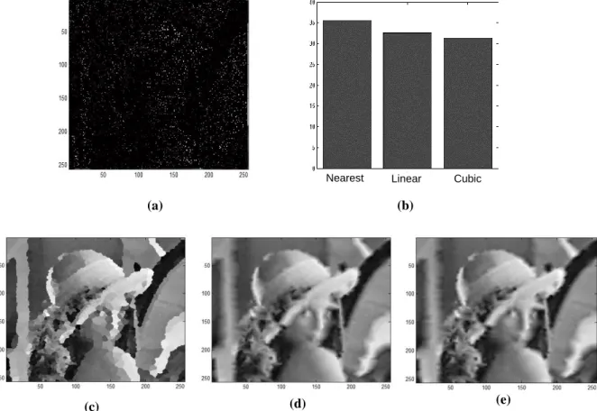
... 33 Figure 2.26 - The SmartEyes OUI (Hadjileontiadis et al., 2003). ... 34 Figure 2.27 - The GSmart Mini digital camera (Hadjileontiadis et al., 2003). ... 35 Figure 2.28 - The Murata ultrasonic sensor and its directivity in SPL (Hadjileontiadis et al., 2003). ... 35 Figure 2.29 - (a) Plexiglas mounted stereo vision system (Hadjileontiadis et al., 2003). ... 36 Figure 2.30 - The SmartVision algorithm operation (Hadjileontiadis et al., 2003). ... 37 Figure 2.31 - The estimated depth of previous figure (Hadjileontiadis et al., 2003). ... 37 Figure 2.32 - The depth map segmentation grid (Hadjileontiadis et al., 2003). ... 38 Figure 2.33 - (a) The VIB MOTOR ASSY 1,3V 115mA microvibrators (Hadjileontiadis et al., 2003). ... 39 Figure 3.1 - EMD block diagram (Chowdhury et al., 2013). ... 53 Figure 3.2 – (a) The test signal with local maxima and minima marked by red and blue dots respectively. (b) The test signal with upper, lower and mean envelop in red, blue and black respectively. (c) The result of one iteration in the IMF sifting process with upper, lower and mean envelop in red, blue and black respectively. (d) The resulting first IMF with upper, lower and mean envelop. (e) and (f) Iteration for the second IMF. From Linderhed, (2005). ... 55 Figure 3.3 – EMD decomposition with algorithm proposed by Huang (Pinto, 2009). ... 56 Figure 3.4 - EMD decomposition with algorithm proposed by Rilling (Pinto, 2009). ... 56 Figure 3.5 - Peano-Hilbert framework for image transformation. ... 60 Figure 3.6 - Peano-Hilbert’s Construction Curve. ... 61 Figure 3.7 - Example of the Peano-Hilbert’s construction curve: (a) is the unit interval to unit square mapping, (b), (c) and (d) are the 2nd-order, 3nd-order and 4nd-order curve. ... 62 Figure 4.1 – Finding local extrema points using a moving 3x3 windows. ... 68 Figure 4.2 - Local maxima of Lena image. ... 69 Figure 4.3 - Local minima of Lena image. ... 69 Figure 4.4 – (a) Corrupted 95% Lena image, (b) Interpolation rmse, (c) Nearest neighbour interpolation of corrupted Lena, (d) Linear interpolation of corrupted Lena and (e) Cubic interpolation of corrupted Lena. ... 71
[ xxiii ]
Figure 4.5 – Boundary data extension procedure. ... 72 Figure 4.6 – Number of extrema after each IMF extraction. ... 73 Figure 4.7 - Decomposition of the Lena image with 2D-EMD. ... 74 Figure 4.8 - Decomposition of an Image of the UTAD campus with 2D-EMD. ... 75 Figure 4.9 - Decomposition of the Lena image with 2D-EEMD. ... 77 Figure 4.10 - Decomposition of an Image of the UTAD campus with 2D-EEMD. ... 78 Figure 4.11 - Number of extrema after each IMF extraction. ... 79 Figure 4.12 - Block diagram of the proposed PHEEMD method. ... 81 Figure 4.13 - Number of maxima, minima of IMFs and the residual of the 256x256 Lena image for the PHEEM. ... 83 Figure 4.14 - The decomposition of Lena with the LSEEMD algorithm. ... 84 Figure 4.15 - The decomposition of Lena with the PHEEMD algorithm. ... 85 Figure 4.16 - From top to bottom: Average Fourier Transform of IMFs obtained over 100 realizations of bidimensional Gaussian white noise for the three methods. The simulation with (a) the 2D-EEMD algorithm, (b) the LSBEEMD algorithm, and (c) the PHEEMD algorithm. ... 86 Figure 4.17 - Edge detection of Lena with (a) the 2D-EEMD algorithm [5], (b) the LSBEEMD algorithm [4], and (c) the PHEEMD algorithm. ... 87 Figure 4.18 - Image denoising using PHEEMD algorithm, (a) original image, (b) original image corrupted with Gaussian white noise, (c) filtered image and (d) RMSE minimization. . 88 Figure 4.19 - Inhomogeneous illumination correction using PHEEMD algorithm, (a) original image, (b) histogram of original image, (c) corrected image and (d) histogram of corrected image. ... 89 Figure 5.1 – General Orientation&Navigation prototype modular structure. ... 92 Figure 5.2 - Three-tier client/server architecture. ... 93 Figure 5.3 - Overall architecture. ... 94 Figure 5.4 - Pushbuttons interface. ... 96 Figure 5.5 - Results of the application of the Dijkstra SPF algorithm. ... 98 Figure 5.6 - Bumblebee2 stereo system (PGR, 2016). ... 99 Figure 5.7 – Block diagram of our computer vision model. ... 101 Figure 5.8 – Chest mounted camera. ... 102 Figure 5.9 – Head mounted camera. ... 102
position of the blind and safe walking area window. ... 103 Figure 5.11 – Example of UTAD campus images characteristics. ... 104 Figure 5.12 – Pre-processing applied to the typical Landmark feature detection. ... 105 Figure 5.13 - Bumblebee2 stereo system, (a) is the source of chromatic images and (b) their depth map (PGR, 2016). ... 106 Figure 5.14 - Depth image layer levels. ... 106 Figure 5.15 – 2D-EEMD disparity image decomposition. Figure (a) is the real image, (b) is the disparity image, (c) to (g) are the IMFs and (h) is the Residue. ... 107 Figure 5.16 - Peano-Hilbert EEMD disparity image decomposition. Figure (a) is the real image, (b) is the disparity image, (c) to (g) are the IMFs and (h) is the Residue. ... 108 Figure 5.17 – Route aerial view of the test scenario 1 (Google, 2016). ... 109 Figure 5.18 – Image road view example of test scenario 1 (Google, 2016). ... 109 Figure 5.19 - Route aerial view of the test scenario 2 (Google, 2016). ... 110 Figure 5.20 - Image road view example of test scenario 2 (Google, 2016). ... 110 Figure 5.21 - Results of the Hough Transform for Circle Detection. ... 112 Figure 5.22 - Results of the 2D-EEMD algorithm for landmarks detection. ... 113 Figure 5.23 - Results of the proposed PHEEMD algorithm for landmarks detection. ... 114 Figure 5.24 - Ground plane detection camera geometry. ... 115 Figure 5.25 - Ground plane detection algorithm. Figure (a) Intensity image, (b) ROI in disparity image for GPD and (c) GPD slope for our camera setup. ... 116 Figure 5.26 - Results of the algorithm for obstacle detection. Figures (a) and (e) are real images, (b) and (f) are filtered 2D-EEMD disparity images, (c) and (g) are disparity images segmented at one meter, (d) and (h) are disparity images segmented at two meters. ... 117 Figure 5.27 - Results of the algorithm for obstacle detection. Figures (a) and (e) real images, (b) and (f) 2D-EEMD filtered disparity images, (c) and (g) segmented disparity at two meters, (d) and (h) real object segmentation. ... 117 Figure 5.28 - Results of the proposed algorithm for obstacle detection. Figures (a) and (e) are real images, (b) and (f) are filtered PHEEMD disparity images, (c) and (g) are disparity images segmented at one meter, (d) and (h) are disparity images segmented at two meters. ... 118
[ xxv ]
Figure 5.29 - Results of the proposed algorithm for obstacle detection. Figures (a) and e) real images, (b) and (f) are PHEEMD filtered disparity images, (c) and (g) segmented disparity at two meters, (d) and (h) real object segmentation. ... 119 Figure 5.30 - Correction angle intervals. ... 121
[ xxvii ]
L
IST OF
T
ABLES
Table I - Execution Speed Ratios for the Three xEMD Algorithms*. ... 82 Table II - Complexity analysis of the SP for xEMD Algorithms. ... 82 Table III - Outdoor features mapped. ... 94 Table IV – Comparison values of chest and head camera oscillations. ... 102
[ xxix ]
A
CRONYMS
1D - One Dimension
2D - Two Dimension
3D - Three Dimension
API - Application Programming Interface
BEMD - Bi-dimensional Empirical Mode Decomposition CCI - Cross Correlation Index
COTS - Commercial-Off-The-Shelf
CPU - Central Processing Unit
CV - Computer Vision
DGPS - Diferential GPS
DLL - Dynamic Link Library
DRGP - Dynamic Recalibration of the Ground Plane EEMD - Ensemble Empirical Mode Decomposition EERUF - Eliminating Rapid Ultrasonic Firing
EM - Expectation-Maximization
EMD - Empirical Mode Decomposition
ENVS - Electro-Neural Vision System ETA - Electronic Travel Aids
FFT - Fast Fourier transform
FM - Frequency Modulated
FRS - Fuzzy-like Reasoning Segmentation
FT - Fourier transform
GIS - Geographic Information System
GPD - Ground Plane Detection
GPOD - Ground Plane Obstacle Detection GPRS - General Packet Radio Service
HCI - Human Computer Interaction
HCT - Hough Circle Transform
HHT - Hilbert-Huang Transform
HMI - Human Machine Interaction
HSA - Hilbert Spectral Analysis
HT - Hilbert transform
ID - IDentifier
IEEE - Institute of Electrical and Electronics Engineers IMF - Intrinsic Mode Functions
LAN - Local Area Network
LASER - Light Amplification by Stimulated Emission of Radiation LBS - Locations Based Services
LGG - Local Global Graph
LRS - Laser Range Scanner
LSEEMD - Line Scan EEMD
MIDI - Musical Instrument Digital Interface NADA - Noise Assisted Data Analysis NAU - Navigation Acquisition Unit NCU - Navigation Control Unit NUI - Navigation User Interface
OAS - Obstacle Avoidance Systems
OAU - Orientation Acquisition Unit OCU - Orientation Control Unit OUI - Orientation User Interface PDA - Personal Digital Assistant
PGR - Point Grey Research
PHEEMD - Peano-Hilbert Ensemble EMD PI - Point of Interest
PSNR - Peak Signal-to-Noise Ratio RFID - Radio Frequency IDentifiers RISC - Reduced Instruction Set Computer
[ xxxi ]
RMSE - Root Mean Square Error Minimization
ROI - Region Of Interest
SD - Standard Deviation
SDEMD - Single Direction EMD
SDK - Software Development Kit
SFC - Space Filling Curves
SMS - Short Message Service
SP - Sifting Process
STFT - Short Time Fourier Transform
STT - Speech-to-Text
SWA - Safe Walking Area
SWAW - Safe Walking Area Window
TENS - Transcutaneous Electro-Neural Stimulation
TTS - Text-to-Speech
USB - Universal Serial Bus
UTAD - Universidade de Trás-os-Montes e Alto Douro
WHO - World Health Organization
[ xxxiii ]
L
IST OF
P
UBLICATIONS
The work developed within the context of this thesis has led to the following publications: International Indexed Journals
1. Fernandes, H., Costa P., Filipe, V., Paredes, H., Barroso, International Journal
Universal Access in the Information Society (2017).
https://doi.org/10.1007/s10209-017-0570-8
2. Costa, P.; Barroso J.; Fernandes, H.; Hadjileontiadis, L.; (2012). Using Peano-Hilbert space filling curves for fast bidimensional ensemble EMD realization, EURASIP Journal on Advances in Signal Processing, 21 August 2012.
3. Costa, P.; Fernandes, H.; Vasconcelos, V.; Coelho, P.; Barroso, J.; Hadjileontiadis, L.; (2011) "Fiducials marks detection to assist visually impaired people navigation", JDCTA: International Journal of Digital Content Technology and its Applications, Vol. 5, No. 5, pp. 342-350, AICIT, 2011, doi:10.4156/jdcta.vol5.issue5.38.
International Conferences with Referees
1. P Costa, H Fernandes, J Barroso, H Paredes, LJ Hadjileontiadis, Obstacle detection and avoidance module for the blind, Proceedings of the World Automation Congress (WAC), 2016, 1-6.
(http://ieeexplore.ieee.org/abstract/document/7582990/)
2. Paulo Costa, Hugo Paredes, Vitor Filipe, João Barroso, (2014). Integrating Computer Vision Object Recognition with Location Based Services for the Blind. 16th International Conference on Human-Computer Interaction. 22 - 27 June 2014, Creta Maris, Heraklion, Crete, Greece
the blind supported by RFID technology". 5th International Conference on Software Development for Enhancing Accessibility and Fighting Info-Exclusion, University of Vigo, Vigo, Spain. Published by Procedia Computer Science. (http://www.sciencedirect.com/science/article/pii/S1877050914000040)
4. Paulo Costa; Hugo Fernandes; Paulo Martins; João Barroso; Leontios Hadjileontiadis; (2012). “Obstacle detection using stereo imaging to assist the navigation of visually impaired people”. DSAI 2012 – 4th International Conference on Software Development for Enhancing Accessibility and Fighting Info-exclusion, Porto, Portugal, 2012. ISBN: 978-989-704-089-4. Published in Procedia Computer Science Journal, Elsevier.
5. Costa, P.; Fernandes H.; Vasconcelos, V.; Coelho, P.; Barroso, J.; Hadjileontiadis, L.; (2011). "Landmarks detection to assist the navigation of visually impaired people", proceedings of HCI International 2011, Orlando, Florida, USA, 2011, Lecture Notes in Computer Science, 2011, Volume 6763/2011, 293-300, DOI: 10.1007/978-3-642-21616-9_33.
6. Fernandes, H., Costa, P., Filipe, V., Hadjileontiadis, L., Barroso, J., (2010) – “Stereo Vision in blind navigation assistance”, Proceedings of the World Automation
Congress 2010 – WAC2010, Kobe, Japan.
(http://ieeexplore.ieee.org/xpl/articleDetails.jsp?tp=&arnumber=5665579&queryT ext%3Dbarroso+douro).
7. Paulo Costa, Hugo Fernandes, João Barroso, Paulo Coelho, and Leontios J. Hadjileontiadis, (2010) – “Fiducials Marks detection to Assist Visually Impaired people Navigation”, Proceedings of the 3rd International Conference on Software Development for Enhancing Accessibility and Fighting Info-exclusion (DSAI2010), Oxford, United Kingdom.
8. Costa, P., Barroso, J., Coelho, P. and Hadjileontiadis, L., (2009) Advanced Image Processing for Computer Vision Systems for Visually Impaired Navigation, Proc. International Conference on Software Development for Enhancing Accessibility and Fighting Info-exclusion, Lisbon, Portugal, June 3-5.
[ xxxv ]
9. Penedo, A., Costa, P., Fernandes, H., Pereira, A. and Barroso, J. (2009) Image segmentation in systems of stereo vision for visually impaired people, Proc. International Conference on Software Development for Enhancing Accessibility and Fighting Info-exclusion, Lisbon, Portugal, June 3-5.
C
HAPTER
1
I
NTRODUCTION
The first chapter presents the context work, the motivations and the project’s mains objectives. The problem investigation, the research questions and the expected contributions are described. At the end it’s also presented the thesis structure overview.
The term “blindness” can create the illusion that there is no type of vision. In medical terms, a person can be considered blind if it possesses a visual acuity less than 3/60, 10% or less vision angle in the better eye (WHO Bouletin, 2010; WHO Glossary, 2007). The World Health Organization estimates a number of 285 million of visually impaired people worldwide (WHO Fact Sheet, 2017), 39 million are totally blind and 246 million have low vision. The blind people still face other challenges in the attainment of the information, as it is known that the major amount of information collected during the learning process is from visual stimulations (Shams, 2002). The blind or visually impaired people have a considerable disadvantage and have frequently a lack of information to exceed the obstacles and dangers, and have relatively few information about the landmarks, routing and proper speed. This type of information is essential to define the individual navigation through familiar environments (Dodds, Howarth, & Carter, 1982), or navigation on unfamiliar environments based on external maps and sensorial indications (speed, tactile, etc.).
However, none of these obstacles are insuperable, with technology evolution and its application in the area, new perspectives are open in the way people with visually disabilities are assisted taking them to carry on their tasks that another way would be almost impossible.
According to Brambring (Brambring, 1984), human mobility consists basically of two components, orientation and navigability. The first one consists of the basic knowledge of objects positions information in the environment and the relation between them (Bentzen, 1979). It means to know the destiny and user’s direction to trace a route through environment to the specified place. As for navigability it has a large local meaning, and signifies the ability to move in the local environment, the immediate knowledge of the objects and obstacles (Farmer, 1979), floor characterization (pathway, holes, stairs, pavements, etc.), the stationary and movement dangers that are all necessary for real time navigation.
Currently technology evolution to assist navigation of visually impaired people is growing fast and making use of technologies such has sonar, laser, computer vision and presently satellite, according to Institute for Innovative Blind Navigation.
Thus, the present work is to propose a computer vision module that uses stereo vision that will integrate with the SmartVision project (Costa et al., 2010) and with its successors, the Blavigator and CE4Blind projects.
The captured images are processed to perform normalization and then segmented to extract the useful information to pass to the blind user.
The main objective is to develop a cheap and easy to use mobile navigation system that helps visually impaired people to navigate and the system is built in a modular structure combining several technologies, described later in the document.
1.1 - Motivation
The strong motivation to initiate this project is to be involved in a community that supports and provides help to those people with a vision disability and contribute to improve their quality of life. This project presents an effort to assist those people in becoming more mobile with a greater degree of psychological comfort and independence. Further motivations mentioned below are taken into account to improve wearable systems that use computer vision to assist visually impaired navigation based on work that has been presented in previous studies. Current systems to assist visually impaired navigation still have many difficult issues to address and I highlight two of them in different areas; the first one is the validation of the usability of the systems by the visually impaired, the second one is in computer vision area with big challenges to overcome. In computer vision area there are many challenges to generalize a
CHAPTER 1INTRODUCTION
model applied to a specific situation. Difficulty in interpreting unstructured environments and not previously known, perform a compact and lightweight system and using the current mobile technologies.
However, as mentioned, recognizing the problems inherent in such systems, they are of such importance and need for improvements that clearly increase the motivation to develop the work presented in this thesis.
1.2 - Scientific contributions
Advances of technology and better knowledge in human psycho-physiological three-dimensional world perception permit the design and development of new powerful and fast interfaces assisting humans with disabilities. For the blind, research on supportive systems has traditionally focused on two main areas: information transmission and mobility assistance. Problems related to mobility assistance are more challenging. They involve spatial information of the immediate environment, orientation and obstacle avoidance. Many electronic travel aids (ETAs) for safe and independent mobility of the blind have been proposed over the last years. They all share the same operation principle: they all scan the environment (using different technologies) and display the information gathered to other senses (mainly hearing and touch). The computer vision model must deal with large amounts of image data (high bandwidth process) and provide useful information to the user (Human Computer Interaction - HCI) which is typically a low bandwidth process. This is a critical task because the filtered information has to be reliable.
In the context of assisting visually impaired people our project integrates with SmartVision and its successors Blavigator and CE4Blind which are the global projects and its aim is to provide navigation and information’s services to the blind. In the project, the computer vision module is perhaps the most challenging task. The vision module must deal with real time or almost real time information, for example, of obstacles that may exists in the pathway in front of the blind user and be able to recognize landmarks placed on the floor to give correct user position along predefined routes.
-The first is to conduct a literature review covering all aspects related with navigation systems to assist visually impaired with a special focus on those with computer vision and image processing techniques. This will include design and systems architectures;
-The second contribution is to propose and validate a new development of the empirical mode decomposition (EMD) (Huang et al., 1998) method to address the computation demands on its two-dimension implementation (2D EMD). Using a Peano-Hilbert space filling curve in conjunction with one dimension EMD to reduce computations demands. From the different image processing techniques, we chose this recently presented because of its ability to process signals in frequency domain without losing its spatial relations;
-Propose and describe a new computer vision model using our Peano-Hilbert EMD algorithm along with implementation tests using different scenarios to validate the accuracy and reliability of the method to extract correct features to give the correct guidance information to the blind user.
1.3 - Thesis Overview
The structure of the work is reflected on the thesis layout. Following this introductory chapter, the document includes five more chapters and bibliography. In the following paragraphs a brief content description for the six chapters is presented.
Chapter 1 is the present chapter and contextualizes the work, expose the motivations and identifies the objectives and main contributions of this thesis.
Chapter 2 provides the summary of the literature review and related work to fully understand the main aspects of the project. It also introduces the base description and classification of the technical aspects of the systems to assist visually impaired navigation. At the end identifies critical aspects of using computer vision techniques on existing systems and formulates a new approach.
Chapter 3 presents the Empirical Mode Decomposition (EMD) algorithm as the main image processing technique used in the project. The EMD algorithm is analysed in its one dimension (1D) configuration and then in two dimensions (2D) adaptation for image processing. Follow the two dimensions characterization and take into account its computer demands for real time applications a major contribution is developed for reducing computer processing needs.
CHAPTER 1INTRODUCTION
Chapter 4 corresponds to one of this thesis major contribution previously indicated. In this chapter a new EMD method is proposed to address the computation demands of the 2D-EMD. Using a Peano-Hilbert space filling curve to implement dimension reduction in the data and in conjunction with 1D-EMD to achieve the objective, i.e., reduce computations demands. Furthermore, the chapter includes validation and several applications in image processing of the proposed method.
Chapter 5 details and analyse the prototype of the propose computer vision module for our project. This is the second major contribution in this work. The chapter begins with a characterization and description of the different modules of the Orientation&Navigation project. Following is the description of the proposed computer vision model using our Peano-Hilbert EEMD algorithm and a comparative test with the fully two dimension ensemble empirical mode decomposition (2D-EEMD). Finally, tests were implemented using different scenarios in the UTAD campus to validate the accuracy and reliability of the method to extract useful and correct information of obstacles presents near the blind and give correct guidance information.
Chapter 6 concludes our work resuming the results and main contributions and suggests future work in order to lead to a better and robust system.
C
HAPTER
2
N
AVIGATION SYSTEMS FOR VISUALLY IMPAIRED PEOPLE
The second chapter introduces the contextual theory of visually impaired or blind mobility. In this context presents the literature review of state-of-the-art of electronic travel aids for the blind. The emphasis is on navigation systems that help blind or visually impaired people in the mobility process. At the end we draw some contributions of our work.
Human beings have the ability to acquire and use information obtained from the surrounding environment using their natural sensors. They have developed a number of evolutionary mechanisms that enable the distinction between different objects and the triggering of events and complex processes based on their perception of reality. Cognition concerns knowledge and knowing in intelligent entities, especially by human beings, but also non-human animals and synthetic computational entities such as robots (Montello, 2009).
Cognition includes the mental structures and processes involved in perception, attention, thinking and reasoning, learning, memory, linguistic and non-linguistic communication. It also includes external symbolic structures and processes, such as maps or written procedures for carrying out formal spatial analysis, which assist internal cognition. Similarly, cognition is often about space, place, or environment, so cognitive acts are quite often of geographic nature (Montello, 2009).
Cognitive mapping (Jacobson, 1998) is of extreme importance for individuals in terms of creating a conceptual model of the surrounding space and objects around them, thereby supporting their interaction with the physical environment (Jacquet, Bellik, & Bourda, 2006). In new environments, finding your way can be time consuming and may require a considerable amount of attention. In these types of scenario, visual impairment is a major limitation to user mobility. On the one hand, individuals with visual impairments often need the help of sighted people to navigate and cognitively map new environments, which is time consuming, not always available and leads to lower mobility (Passini, Proulx, & Rainville, 1990). On the other hand, individuals with cognitive impairment may experience difficulty in learning new environments and following directions.
Assistive systems for human navigation generally aim to allow their users to safely and efficiently navigate in unfamiliar environments, without getting lost, by dynamically planning the path based on the user’s location, respecting the constraints posed by their special needs. Collecting the specific needs or specificities of any impairment is a key point for the development of any assistive system. Using direct observational and interview based knowledge elicitation methods, researchers of The Haptic Sight study (Song & Yang, 2010) tried to gain a better understanding of a visually impaired person’s indoor walking behaviour and the information required for him to walk independently. They found that the visually impaired need to be aware of their current location, the direction they are heading, the direction they need to go and the path to their destination. Only after the research team had identified these parameters they develop a handheld device-based application. In other words, users with visual impairment must be aware of their physical location, their relation to the surrounding environment (context) and the route they must follow to navigate to a desired destination. When designing an assistive system for human navigation, separate processing units (or modules) can address these identified tasks, namely location, orientation, navigation and interface.
This work reviews different ways with which different researchers addressed the use of technology to fill the gaps and needs presented by visual impairment in each of these topics. As with the design of any assistive system, the interface with the user must be adequate to the user’s limitations.
CHAPTER 2NAVIGATION SYSTEMS FOR VISUALLY IMPAIRED PEOPLE
2.1 - Characterization of the Navigation systems
An Electronic Travel Assistance (ETA) has to supply to the visually impaired people the necessary routing information to overcome obstacles in the near environment with a minimum rate of errors. This displacement between the origin and the destination is done according to the programmed route. A distinction must be made between primary support systems such as guide cane and guide dogs, and the secondary ones that use of the most recent technology.
The secondary systems are object of current study and consist of a wearable or handheld computer with Global Position System (GPS) responsible for the macro navigation (Petrie et al., 1996). In order to prevent collision with obstacles (micron navigation) (Petrie et al., 1996) these secondary systems also make use of services of primary navigation systems. Collins and Loomis were the first ones to propose independently the use of GPS to assist navigation of the visually impaired people, in the middle eighties decade in their navigations systems (Loomis, Golledge, Klatzky, Speigle, & Tietz, 1994).
According with the proposed model by Loomis (Loomis, Golledge, Klatzky, Speigle, & Tietz, 1994) a system to assist navigation of visually impaired people is organized in three basic components: 1) position unit and orientation; 2) Geographic Information System (GIS); 3) User interface. The Figure 2.1 shows the Loomis’s proposed block diagrams for his navigation systems. It can be seen the position unit and the orientation block with several sensors for macro and micro navigation, GIS block for route planning and user interface block to provide feedback to blind people.
Figure 2.1 - Functional block diagram of the navigation system proposed by Loomis (Loomis et al., 1994).
2.1.1- Position unit and orientation
This functional component is responsible for supplying to the navigation system the user’s spatial location, in the form of local and global coordinates. This module processes the
position information provided by the GPS system, i.e., orientation and global position, with the one provided by a set of the different sensors, speed, inertial, ultra-sonics, video cameras, i.e., navigability, local positioning and obstacles detention, giving a pre-processed information to the GIS module.
This is the functional block that specifically characterizes the navigation systems as
indoor or outdoor and has a number of possible implementations possibilities and categories,
some of them described below:
GPS originally Navstar GPS is a space-based radionavigation system created by the
United States and operated by the United States Air Force. It is a global position satellite system that provides geolocation and time information to a GPS receiver. This GPS receiver could be anywhere near the Earth and in an unobstructed line of sight to four or more GPS satellites. Depending on the signal reception conditions and user’s location, the GPS provide latitude and longitude information with a dozen of meters precision. With a differential GPS configuration, it is possible to improve positions precision in the range of a meter or less. However, the GPS signal is not available in all places, inside buildings and places where the signal of the satellites could possibility be out of sight by any another obstacle (Loomis, Golledge, Klatzky, Speigle, & Tietz, 1994);
Computer vision in its based design can use one or two cameras to extract features that contain contextual information about a specific scenario. Most of them use image matching techniques to determine the user’s position who holds the camera system. Several image processing algorithms, including those for image feature extraction and image recognition can be used for fiducial marks detention. Image vision recognition used by users without visual disabilities is used to enhance their skills. However, a blind user has a higher difficulty to point the camera to the desired poit of interest, thus difficult its usability. For specific marks detection exists some software libraries that use augmented reality to enhance visual capabilities, like Artoolkit (Artoolkit, 2016). Kim (Kim & Jun, 2008) developed vision based augmented reality for indoor navigation;
Radio Waves and Radio Frequency Identifiers (RFID): the use of this type of technology for determining user’s positions has increased, due to the fact that many companies have installed wireless networks infrastructures in their campus (IEEE 802.11, 2017), or use the new position services provided by other mobile networks operators. By using triangulation methods,
CHAPTER 2NAVIGATION SYSTEMS FOR VISUALLY IMPAIRED PEOPLE
it is possible to determine the distance of the receiver (users) relatively to the emitters and achieve the user’s position with several meters precision. With the use of RFIDs it’s also possible to determine the user’s position inside a campus, as these tags transmit its identification information contained in memory to a user carrying a special receiver (visually impaired) that pass nearby. In a context of indoor navigation support system, these tags can be placed in specific locations providing specific position information to the user (Willis & Helal, 2005);
Intelligent Floors are able to identify a user who walks on the floor in indoor environments, i.e., in controlled and closed environments. With specific sensors located on the floor and connected to a computer system to process data and identify users based on their typical walking characteristics. Upon user detection the system can interact and send active position information to the blind user (Addlesee, Jones, Livesey & Samaria, 1997 ; Orr & Abowd, 2000).
2.1.2- Geographic Information System (GIS)
This functional block is an essential component of the navigation systems. Its main function is to store additional information about user’s position, navigation maps, objects positions and possible dangers.
In its local or remote database Points of Interest (PIs) like bookstores, museums, restaurants can be stored, and the system can inform the user about its location. Normally this functional component integrates a spatial database with several maps and predefined routes, and in real-time navigation mode the system provides to the user its location information.
In addition to position information the system must provide precise characteristics of local environment, for local sensors like vision system can be able to recognize it. The user must be able to add to the stored spatial database additional cartographic maps adapted to him, making a customized navigation system (Loomis, Golledge, Klatzky, Speigle, & Tietz, 1994). This module is responsible for output feedback information to the next component, the user interface module.
2.1.3- User Interface
The user interface is one of the most important component in the navigation system, mainly to assist visually impaired people because it acts as a vision substitution sensing (or trying to be) and must be user friendly.
In general, it is possible to state that in alternative to vision substitution, any other human sense can be used. However, the use and choice should be carefully studied as they may interfere with other tasks also important for the blind user. Also, it must take into account, that the non-visual senses have a lower capacity transmission than visual sense (Strumillo, 2010).
In the context of navigation systems technologies to assist visually impaired people, the most common interaction forms with the blind user are: audio coding; audio description; and tactile interfaces.
Hearing user interface method is used by several navigation systems to assists visually impaired people, some examples are presented later. In general, this type of user interface can provide interaction information from speech synthesizer (audio description) or generating sound patterns (audio coding) that are understand by the user. A new type of virtual audio interface output is under development to provide spatial audio information of the objects location in the environment. According to Strothotte (Strothotte et al., 1996) in some situations audio feedback is not the most suitable because it can override the natural sound of the environment and create distractions in user information perception. This can leave to misunderstandings of ambient sounds and may put visually impaired users in danger. Manduchi and Coughlan (Manduchi & Coughlan, 2012) state that "an important issue to be considered in designing a user interface is whether a rich scene description, or only a highly symbolic information should be provided to the blind user."
Tactile interfaces are another form of interaction with visual disabilities users. In this field are included keyboards, Braille displays and several different vibrating devices (Hadjileontiadis, Trichakis, Bisias, Taplidou, & Korkontzila, 2003). This is the type of interface can also be used to send deep information to the blind in an identical way as in a Braille interface (Pissaloux, Maingreaud, Velázquez and Fontaine, 2006). Tactile feedback is often associated with information also sent to hearing, Ross and Blasch (Ross & Blasch, 2000) concluded that best user interface combines these two user senses.
2.2- Presentation of some Navigation Systems
The navigation systems to assist visually impaired people can be classified in three groups based on the usage. The indoor systems are intended to be used in structured environments with less complex scenes, typically inside buildings or in isolated controlled
CHAPTER 2NAVIGATION SYSTEMS FOR VISUALLY IMPAIRED PEOPLE
campus. The outdoor navigation systems are intended to be used in exterior open space, typically on the street. The indoor/outdoor systems can be used in both indoor and outdoor spaces, switching functionalities based on environment operation.
The outdoor navigation system usually follows the base model proposed by Jack Loomis (Loomis, Golledge, Klatzky, Speigle, & Tietz, 1994), and have three essential modules. The first module has a GPS system and several other sensors to provide position and orientation information. The second module is the geographic information system with a cartographic data base and route planning software. The third module is the user interaction, it receives and process data from other modules to provide correct and accurate information to the user. This information can be grouped in system configuration based commands and route guidance.
In the next paragraphs some commercial and Research and Development (R&D) projects that currently describe the state of the art in outdoor navigation systems to assist visually impaired people will be described.
The projects presented are organized in two groups according to their characteristics and implemented modules. The first group includes projects that provide orientation information and user interaction, local navigability is added by canes and/or guided dogs. The second group adds the local navigability relatively to the previous one. This local information is very important to detect and avoid obstacles. From the projects described a special attention is given to the ones that have incorporated a computer vision module.
2.2.1- Systems without local information / GPS based systems
BrailleNote GPS, (Sendero GPS, 2017) – GPS based system to assist navigation of visually impaired people. Its main part is a mobile phone specially adapted for people with visual disabilities, a GPS receiver and special developed software for configuration, orientation and route mapping. On Figure 2.2 a smartphone adapted with a Braille display and a GPS receiver are represented.
The BrailleNote from HumanWare Group (HumanWare, 2017) supports traditional computer applications and was designed to supply blind people special needs; the output user interaction can be from Braille or a speech synthesizer. From the sendero GPS it’s possible to configure the smartphone with automatic routes to the user’s destination, get distance from PIs nearby, get velocity information, direction and altitude during the trip.
Figure 2.2 - Sendero BrailleNote GPS (Sendero GPS, 2017).
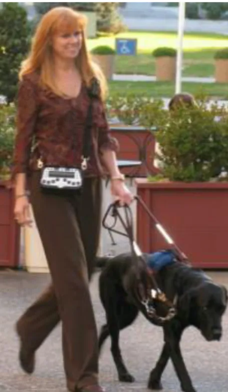
Figure 2.3 shows a blind user walking assisted with Sendero GPS and the local spatial information given by a guide dog.
Figure 2.3 - Sendero GPS navigation system in use (Sendero GPS, 2017).
StreetTalk, (FreedomScientific, 2010) - GPS based system to assist navigation of visually impaired people. The system is functionally identical to Sendero’s BrailleNote GPS and also uses standard components, a mobile phone specially adapted the for visually impaired needs, a Bluetooth GPS receiver and the proprietary software Destinator. The Destinator software has a local database, GIS functionalities and route planning according user’s preferences. On Figure 2.4 (a) it is show a snapshot of the software Destinator and Figure 2.4 (b) shows a standard mobile with Braille a display. The user interface can be a tactile device or via audio headset.
CHAPTER 2NAVIGATION SYSTEMS FOR VISUALLY IMPAIRED PEOPLE
(a) (b)
Figure 2.4 - Global parts of StreetTalk navigation system (FreedomScientific, 2010).
In the audio interaction with blind user are used vocal commands to inform user about orientation, PIs localization and system management.
Victor Reader Trek, (HumanWare, 2017) – GPS based system to assist navigation of visually impaired people. The system is functional identical to Sendero’s BrailleNote GPS and also uses standard smartphone specially adapted the for visually impaired needs, a GPS receiver and the proprietary software. The software has a local data base, GIS functionalities, route planning according user’s preferences, and standard applications package. Figure 2.5 (a) shows a blind user walking assisted by the trekker navigation system and the local spatial information that is given by a white cane. On Figure 2.5 (b) it is shown an adapted mobile phone with special adapted keyboard to be used by blind people.
(a) (b)
Figure 2.5 - (a) Trek navigation system in use, (b) Phone adapted for blind users (Humanware, 2017). The user interface can be from tactile device or via audio headset. In the audio interaction with blind user vocal commands are used to inform user about orientation, PIs localization and system management.
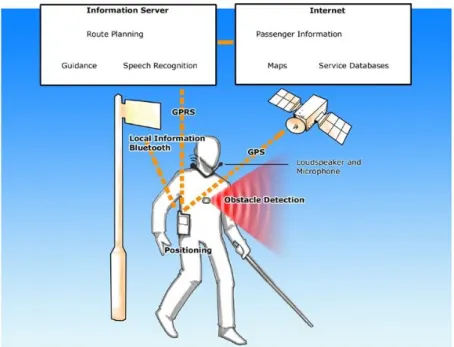
NOPPA, (Ari & Sami, 2004) – Navigation and Guidance System for the Blind, was developed in VTT Technical Research Centre of Finland between the years 2002 and 2004. The developed system can be used by people with or without visual disabilities, because the services provided by the system are useful for any user.
A functional diagram is show on Figure 2.6, where the three modules proposed by Loomis can be identified. In the same figure it is shown that the Internet and Information servers are accessed through a General Packet Radio Service (GPRS) connection. The Information Server has the route planning, guidance and speech recognition, the Internet Server has the passenger information, maps and services database.
Figure 2.6 - NOPPA’s general overview (NOPPA, 2006).
The system is based on a Qtek Pocket PC with Global System for Mobile communications (GSM), GPRS to the servers and a Bluetooth link to GPS receiver. The system has the functions/services identical to the previously described; in addition, it can provide information about public transportation services. However, this service is only available in major cities from Finland.
Due to PDA processing capabilities the route processing and speech recognition are made on the server. The planed route is sent to PDA terminal which gives the user routing guidance information. A GPRS connection is established between PDA and Information server during the walking for additional exchange information.
CHAPTER 2NAVIGATION SYSTEMS FOR VISUALLY IMPAIRED PEOPLE
AudioGPS, (Holland, Morse, & Gedenryd, 2002) - Spatial Audio Navigation with a Minimal
Attention Interface, is a system to assist navigation of visually impaired people and is based on
a laptop computer with MS Windows or Apple Macintosh. A Musical Instrument Digital Interface (MIDI) is used to control the processing audio software for user interaction. The Figure 2.7 shows the AudioGPS system based on a wearable computer and a GPS antenna on top.
Figure 2.7 - AudioGPS system in use (Holland et al., 2002).
The system was developed on the concept of minimal attention interface. Kristoffersen (Kristoffersen & Ljungberg, 1999) and Pascoe (Pascoe, Ryan, & Morse, 1999) proposed interfaces that require minimal attention from the user without losing information quality. Virtual audio and speech commands are the two types of audio user interface. The first one is used for navigation information (direction and distance to destiny) and the second one is used for route planning.
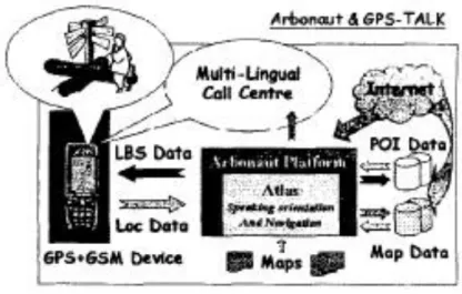
Pharos, (Marsh, Mag, & Saarelainen, 2000) - Coupling GSM & GPS-TALK technologies to
provide orientation, navigation and location-based services for the blind, it includes Sendero’s
developed system (previously described) and the Arbonaut Locations Based Services (LBS) portal (Arbonaut, 2008). The system provides orientation, maps management, route planning, PIs description among others, through speech commands, and still provide LBS through internet access.
Figure 2.8 - Pharos Mobility Service (Marsh et al., 2000).
The Figure 2.8 shows the system functional Pharos mobility services and the interaction between GPS-GSM devices and Arbonaut portal services.
The utilization of GPS-GSM and Arbonaut portal services by visually impaired people are: - the user can make automation update to maps, specific routes, PIs among others; - which user can have a personal account with personal profile according its preferences; - the user can be located by another one with the same system or in the Arbonaut portal, if
allowed
Initially Pharos makes available five navigation services:
- the service “Where am I” is activated by the blind user when it wants to know its position by pressing a dedicated key associated with the service. A Short Message Service (SMS) with user IDentifier (ID) location (GPS coordinates) and additional information is sent to the Arbonaut server. If the user is registered, the geo-location is decoded and passed to the Atlas software, then a session agent creates a recorded voice call to be sent back to the user or passes to an information call centre;
- the service “What can I see” is used when the blind user wants information about surrounding environment. By pressing a single key (dedicated soft key) the procedure communication is identical to previous service;
- the service “Am I on route?” is used for guiding blind user through a predefined route, defined by the user or a call centre operator.
CHAPTER 2NAVIGATION SYSTEMS FOR VISUALLY IMPAIRED PEOPLE
- the service “Follow me” uses the Arbonaut Tracking & Scouting service, the blind user’s GPS-GSM handset periodically send a geo-encoded SMS to the Arbonaut server. The server then forwards the position to a predefined observer;
- the service “Rendezvous” is to allow two or more users to define a geo-encoded meeting point, defined via handset or through the Arbonaut web page.
Navigator, (Kowalik & Kwasniewski, 2004) - A Talking GPS Receiver for the Blind, is another system to assist navigation of visually impaired people and does not use a standard phone has a central unit. The system is portable, but all hardware was developed around a microprocessor unit to control all the electronics.
During operation the microprocessor unit receives GPS data at one second interval, and the user interaction is made through speech interface commands. The Central Processing Unit (CPU) also controls the recording of short voice messages from microphone, and the output is from a loudspeaker or headphones.
When the blind user is walking through a predefined routed only the most important changes are sent to them, because excess of information distracts and can put him/her in danger. The main Navigator function can be divided in to three fundamental groups, according to (Kowalik & Kwasniewski, 2004). In the first group are functions that are automatically triggered due to a specific occurrence, for example during the approximation to a previously recorded spot. The second group comprises single key function, there are ten such functions which include for example number of satellite the device can track, the parameter of nearest PI along the route, etc. Finally, the third group are functions operated with a few keys, these are set to change the Navigator operating mode by changing options, read additional operation etc. Drishti, (Ran, Helal, & Moore, 2004), - An Integrated Indoor/Outdoor Blind Navigation System and Service. The system integrates a Differential GPS (DGPS) which has a better position resolution than standard GPS. The DGPS uses terrestrial radio stations to correct possible signal imprecisions from satellites.
The Drishti system can operate in indoor and outdoor environments modes, changing between modes by vocal commands.
In outdoor mode the Drishti works in the same way the previous described systems with the difference that it can modify dynamically the routes according to GIS information.
The major disadvantages of the system are the dependency of DGPS, which is present in few countries, the system size difficult the portability and the use of headphones in the ear mask natural sounds in some situations may put the user in danger.
The Figure 2.9 shows the Drishti in use, the DGPS in the back and the wearable computer.
Figure 2.9 - Drishti in outdoor environment (Ran et al., 2004).
The system uses Commercial-Off-The-Shelf (COTS) hardware and software components. The hardware uses a wearable computer, a DGPS receiver, wireless LAN and ultrasound position device. The software components are a spatial database, route store module, a Mapserver to serve the GIS database, IBM ViaVoice is the runtime speech API and an indoor location service. Trough the voice commands the blind user is able to control and receive information from the Drishti as shown in Figure 2.10.
CHAPTER 2NAVIGATION SYSTEMS FOR VISUALLY IMPAIRED PEOPLE
Figure 2.10 - Drishti user interface (Ran et al., 2004).
In this figure we can look to the first command that represents a change environment mode to indoor and the answer from the system.
SmartEyes, (Hadjileontiadis et al., 2006), - An efficient mobile phone/navigator for blind or visually impaired people, this research project refers to an intelligent mobile Pocket PC based phone combined with a Bluetooth GPS, to assist visually impaired people in usually phone tasks and navigation actions.
The system is designed to provide a wide variety of functionalities to the user, based on two basic engines, the Speech-to-Text / Text-to-Speech and routing (STT/TTS).
The Figure 2.11 shows a diagram of the internal organization of SmartEyes that is comprised of two modules, the navigation and phone ones. The interaction with blind user is from STT/TTS interface.
The navigation module is designed to provide the user all the necessary information regarding his/her current position, provide optimized route to the user’s destination. Additional metadata information is provided to the user, informing the user about PIs during his/her route to the destination. The user has two options in route planning, a) simulate the route in a Personal Computer, define the desired PIs and download the information to the Pocket PC, and b) plan directly in SmartEyes and start for actual route.
Figure 2.11 - SmartEyes modules (Hadjileontiadis et al., 2006).
The phone module refers to the mobile phone of the same Pocket PC and associated with the STT/TTS interface to provide a wide range of functionalities to the user. For example, placing a call activated by voice recognition or read a SMS trough voice commands are services provided by the STT/TTS interface.
During SmartEyes initialization phase the user can connect to a map repository server via web services and, after user authentication procedure download the desired city map, which increase system flexibility.
2.2.2- Systems with local information
The navigation assistant systems with local environment information provide a better knowing of the local scenario, increasing the information quality provided to the blind user to overcome local obstacles. Blind users share the same navigation aspects with the robot mobility (Shoval, Ulrich, & Borenstein, 2000). The Obstacle Avoidance Systems (OAS) developed for robotic mobility can be adapted for the visually impaired people.
Several projects use multiples ultrasonic sensors (sonar) to detect and measure object distances. Sonar has a major disadvantage that cannot detect small objects near the ground (Molton, Se, Bradly, Lee, & Probert, 1998), because of the low angular resolution. By the other side, multiples sensors can cause mutual interference and crosstalk (Shoval, Ulrich, & Borenstein, 2000). Due to this phenomenon, ultrasonic sensors were fired one after another