RO
DissCo
OBUSTN
REINFO
S
sertação parOrientado
-orientado
President Arguente VogaiNESS O
ORCED
STRUCT
ra obtenção Engenharor: Luís
A
Profes
or:
Joan R
Profes
Júri te: Profess es: Profess Profess is: Profess Profess Profess NovembrOF COR
CONCR
TURES
o do Grau d ria Civil
Armando Ca
ssor Auxilia
Ramon Cas
ssor Cated
i:sor Doutor An sor Doutor An sor Doutor Lu sor Doutor Ân sor Doutor Ca sor Doutor Ed
ro 2013
RODED
RETE
de Doutor em
anhoto Ne
ar, FCT/UN
sas Rius,
rático, UPC
ntónio M.F. R ntónio Abel R uís Miguel Pi ngelo Palos T arlos Manuel duardo Nuno
D
meves,
NL
C
R. A. Gonçal Ribeiro Henr na de Olivei Teixeira l Chastre Ro o Brito Santo
ves Coelho iques ra Santos
The work presented in this thesis had the invaluable guidance, support and help of several people and institutions, to which I’m deeply grateful.
In this manner, I would like to express my deep gratitude to Prof. Lu´ıs Neves, my supervisor, for the guidance and sharing of knowledge during the course of this work. I am also grateful to him, for his friendship, and good mood during the difficult times I have faced. Finally, I would like to praise his prompt availability to everything I needed to develop this work.
I also would like to express my deep gratitude to Prof. Joan Ramon Casas, my co-supervisor, for his guidance and friendship. I thank to him particularly the good times I have passed in Polytechnic University of Catalunya, and how well I have been received.
I am highly indebted to Prof. Alfredo Huespe without whom this work would not have been possible. I am also grateful to Prof. Xavier Oliver, Prof. Dorian Linero, Ivo Dias and Prof. Sena Cruz, for their support and for transmitting me fundamental knowledges to perform this work.
I would like to acknowledge Funda¸c˜ao para a Ciˆencia e Tecnologia and Cost Action TU-0601 for help supporting me during the course of this work.
I thank to all my colleagues in the Civil Engeneering Department of Faculdade de Ciˆencias e Tecnologia (Universidade Nova de Lisboa) for backing me during my absences, in par-ticular to Prof. Jo˜ao Rocha de Almeida who always gave me full support in everything concerning this work. I am also specially thankful to Z´e Varandas and Ana Br´as, with whom I shared the cabinet, for the profit discussions and sharing of knowledge.
I thank to Prof. Jos´e Camara, my MSc supervisor and friend, for being an inspiring person to me, and responsible for my initiation in research.
I also would like to express my deep gratitude to my family and friends for their support and care during the course of this work.
The concept of structural robustness has seen growing interest in the last decades due to the occurrence of catastrophic consequences resulting from extreme events. The lack of structural robustness has been several times claimed as the major cause for the unmanage-able consequences. However, the concept has never been accurately defined, and several different perspectives for robustness can be found in the literature.
Structural robustness has been widely discussed for structures subjected to extreme events, however, the concept can also be useful in the context of more probable exposures, such as those resulting in structural aging. In fact, in the last 20 years, most developed soci-eties have been facing the problem of infrastructure aging, and the maintenance demands already represent a significant fraction of governments investments in infrastructures.
In this thesis a deep analysis on the essence of structural robustness is presented. The most relevant definitions and measures for robustness, suggested in the literature, are widely discussed in order to understand the difficulty in achieving a unique and consensual approach.
In the context of structural aging, a new definition for robustness, including a complete methodology to assess it, is proposed in this thesis. Robustness is related with the struc-ture ability to maintain adequate performance levels as damage increases. The competence of the proposed framework to assess robustness is proven in the context of structural aging, in particular in cases of reinforced concrete structures subjected to reinforcement corro-sion. Structural performance of reinforced concrete structures is analyzed as corrosion on reinforcement increases. In this manner, a methodology to assess the most concerning effects, resulting from corrosion is presented. Different performance indicators, both deter-ministic and probabilistic, and structural types are analyzed. Robustness results obtained are discussed regarding the structural types more tolerant to corrosion of reinforcement. Finally the case of an existing bridge, presenting signs of severe corrosion, is analyzed and discussed in the context of the proposed robustness framework.
Nas ´ultimas d´ecadas, tem-se assistido a um interesse crescente pelo conceito de robustez estrutural, devido `a ocorrˆencia de eventos extremos em estruturas dos quais resultaram consequˆencias catastr´oficas. A falta de robustez estrutural tem sido por diversas vezes considerada como a principal causa para a ocorrˆencia consequˆencias desmesuradas. No entanto, o conceito de robustez estrutural nunca foi inequ´ıvocamente definido, como se verifica pelas diferentes perspectivas sugeridas na literatura para o mesmo.
O conceito de robustez estrutural tem sido amplamento discutido no ambito de estruturas sujeitas a eventos extremos, no entanto o mesmo tamb´em pode ter bastante utilidade quando utilizado no contexto de eventos mais prov´aveis, tais como aqueles que resultam no envelhecimento estrutural. De facto, nos ´ultimos 20 anos, as sociedades mais desenvolvidas tˆem-se deparado com o problema do envelhecimento estrutural, sendo que as necessidades de investimento em manuten¸c˜ao representam j´a frac¸c˜oes significativas dos or¸camentos governamentais em infraestruturas.
Uma an´alise detalhada do conceito de robustez ´e por isso efectuada nesta tese. As princi-pais defini¸c˜oes e medidas de robustez encontradas na literatura s˜ao discutidas em detalhe com o objectivo de perceber a raz˜ao pela qual tem sido dif´ıcil chegar a um consenso sobre uma defini¸c˜ao inequ´ıvoca da robustez.
Tendo em vista a problem´atica do envelhecimento estrutural, uma nova defini¸c˜ao para a robustez ´e proposta nesta teste, incluindo uma metodologia de avalia¸c˜ao da mesma. A ro-bustez ´e associada `a capacidade da estrutura de manter n´ıveis adequados de desempenho, quando o n´ıvel de dano aumenta. A competˆencia desta metodologia ´e demonstrada no contexto de estruturas sujeitas a deteriora¸c˜ao, em particular para casos de estruturas de bet˜ao armado sujeitas a corros˜ao das armaduras. O desempenho estrutural de estruturas de bet˜ao armado ´e pois analizado em fun¸c˜ao do aumento do n´ıvel de corros˜ao das ar-maduras. Desta forma, apresenta-se tamb´em nesta tese, uma metodologia para avalia¸c˜ao dos mecanismos de deteriora¸c˜ao mais importantes resultantes da corros˜ao. O impacto da corros˜ao ´e avaliado considerando diversos indicatores de desempenho (determin´ısticos
List of Figures xii
List of Tables xxiii
1 Introduction 1
1.1 Motivation . . . 1
1.2 Contributions . . . 3
1.3 Thesis Organization . . . 4
List of Symbols and Abbreviations 1 2 Structural Robustness 7 2.1 Introduction . . . 7
2.2 Introductory examples . . . 8
2.2.1 Building failure examples . . . 8
2.2.1.1 Ronan Point apartment tower collapse, London, 1968 . . . 8
2.2.1.2 World Trade Center, New York, 2001 . . . 10
2.2.1.3 Bad Reichenhall arena, Germany, 2006 . . . 13
2.2.1.4 Siemens arena, Denmark, 2001 . . . 15
2.2.1.5 Residential building in Coimbra, Portugal, 2000 . . . 17
2.2.2.1 Hintze Ribeiro bridge, Portugal, 2001 . . . 18
2.2.2.2 Penacova bridge, Portugal, 1975 . . . 20
2.2.2.3 I-35W Mississippi River bridge, Minneapolis, 2007 . . . 21
2.3 Collapse development . . . 23
2.3.1 Exposure prevention . . . 25
2.3.2 Damage Prevention . . . 26
2.3.3 Failure prevention . . . 27
2.3.4 Risk related to collapse . . . 29
2.4 Background on robustness definition . . . 30
2.4.1 Different robustness perspectives . . . 30
2.4.2 Structural propertyversus Environmental property . . . 32
2.4.3 Disproportionate collapseversus Progressive collapse . . . 34
2.4.4 Robustness related concepts . . . 35
2.5 Background on Robustness Assessment . . . 36
2.5.1 Deterministic measures . . . 37
2.5.2 Probabilistic Measures . . . 43
2.5.3 Risk Measures . . . 46
2.6 Robustness Index . . . 48
2.7 Examples . . . 52
2.7.1 Steel column . . . 52
2.7.2 Truss system - deterministic approach . . . 55
2.7.3 Truss system - probabilistic approach . . . 59
3.2 The electrochemical process . . . 65
3.3 Corrosion initiation and propagation . . . 67
3.3.1 Carbonation . . . 68
3.3.2 Chloride contamination . . . 70
3.3.3 Generalizedversus localized corrosion . . . 71
3.3.4 Corrosion rates . . . 72
3.4 Mechanical effects . . . 74
3.4.1 Reinforcement area reduction . . . 74
3.4.2 Concrete cracking . . . 75
3.4.3 Bond deterioration . . . 79
3.4.4 Reinforcement ductility reduction . . . 83
3.5 Structural effects . . . 83
3.5.1 Experimental tests . . . 84
3.5.2 Numerical analysis . . . 89
3.6 Final remarks . . . 92
4 Robustness - A deterministic approach 93 4.1 Introduction . . . 93
4.2 Methodology of analysis . . . 94
4.3 Concrete model . . . 95
4.3.1 Concrete isotropic continuum damage model . . . 95
4.3.2 Continuum strong discontinuity approach . . . 100
4.4.2 Section analysis . . . 104
4.4.2.1 Flat slab results . . . 105
4.4.2.2 I-beam results . . . 111
4.4.3 Final Remarks . . . 117
4.5 Second stage: the 2D longitudinal analysis of the structural member . . . . 117
4.5.1 Numerical model . . . 117
4.5.1.1 The homogenized composite material . . . 118
4.5.1.2 Slipping-fiber model . . . 120
4.5.1.3 Bond strength deterioration . . . 122
4.5.2 Case study . . . 123
4.5.3 2D longitudinal model for structural analysis . . . 124
4.5.4 Uncorroded structure . . . 125
4.5.5 Corroded structure . . . 130
4.5.5.1 Coupling Cross section and 2D longitudinal analysis . . . . 130
4.5.5.2 Results . . . 134
4.6 Robustness assessment . . . 138
4.7 Comparison with experimental tests . . . 145
4.8 Final remarks . . . 147
5 Robustness - A probabilistic approach 149 5.1 Introduction . . . 149
5.2 Case-study . . . 150
5.3 Beam numerical model . . . 151
5.4.2.1 Uncorroded structure . . . 156
5.4.2.2 Coupling cross section and structural analyses . . . 158
5.4.2.3 Corroded structure . . . 160
5.4.3 Robustness assessment . . . 161
5.5 Reliability analysis methodology . . . 163
5.5.1 Introduction . . . 163
5.5.2 Random variables . . . 164
5.5.3 Reliability analysis . . . 165
5.5.4 Results . . . 169
5.5.5 Robustness assessment . . . 170
5.5.6 Sensitive analysis . . . 172
5.6 Final remarks . . . 175
6 Robustness of a corroded bridge deck 177 6.1 Introduction . . . 177
6.2 Case-study: Tercenas Bridge . . . 178
6.3 Bridge Condition . . . 180
6.4 Bridge numerical model . . . 181
6.4.1 Finite elements model . . . 181
6.4.2 Materials properties and load effects . . . 185
6.5 Deterministic analysis . . . 187
6.5.1 Bridge deck safety measure . . . 187
6.5.3 Corroded structure . . . 190
6.5.4 Robustness assessment . . . 194
6.6 Probabilistic analysis . . . 196
6.6.1 Random variables . . . 196
6.6.2 Reliability analysis . . . 198
6.6.3 Results . . . 200
6.6.4 Robustness assessment . . . 203
6.7 Final remarks . . . 204
7 Conclusions and Future Work 205 7.1 Conclusions . . . 205
7.2 Future Work . . . 207
2.1 Ronan Point, London, 1968 (adapted from MacLeod (2005)). . . 9
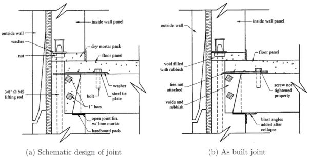
2.2 Exterior horizontal joint between floor slab and flank wall (adapted from Pearson and Delatte (2005)): (a) schematic design of joint; (b) as built joint. 10
2.3 September 11 in New York, USA, 2001 (adapted from Thomas (2011)). . . 11
2.4 World Trade Center exterior wall (adapted from NCSTAR (2005)). . . 12
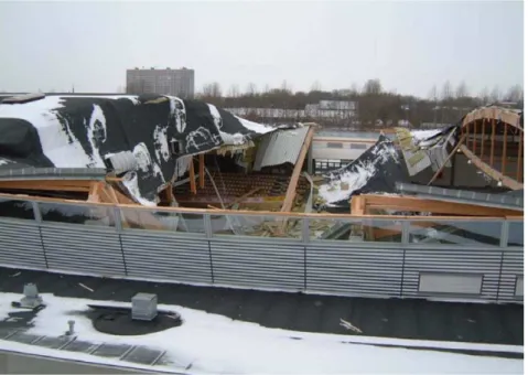
2.5 Bad Reichenhall ice-arena (adapted from Winter and Kreuzinger (2008)). (a) Prior to collapse; (b) After collapse. . . 14
2.6 Bad Reichenhall main box girders design plans (adapted from Winter and Kreuzinger (2008)). . . 14
2.7 The Siemens Arena structure after collapsing. Intact truss on the right (adapted from Munch-Andersen and Dietsch (2011)). . . 16
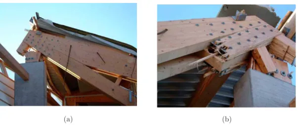
2.8 Siemens arena main truss connections (adapted from (Munch-Andersen and Dietsch, 2011)): (a) corner connection with concealed steel plates, connect-ing the timber parts through bolts and dowels; (b) failure at the critical cross section in the corner connection. . . 17
2.9 Residential building in Coimbra, Portugal, damage by a landslide occurred in January, 2000 (adapted from Tiago and Julio (2010)): (a) rear facade of the building a few days after the accident; (b) detail of the total collapse of the outer columns. . . 18
2.10 Schematic drawing of the strut and tie system developed after the accident (adapted from Tiago and Julio (2010)). . . 19
2001. . . 20
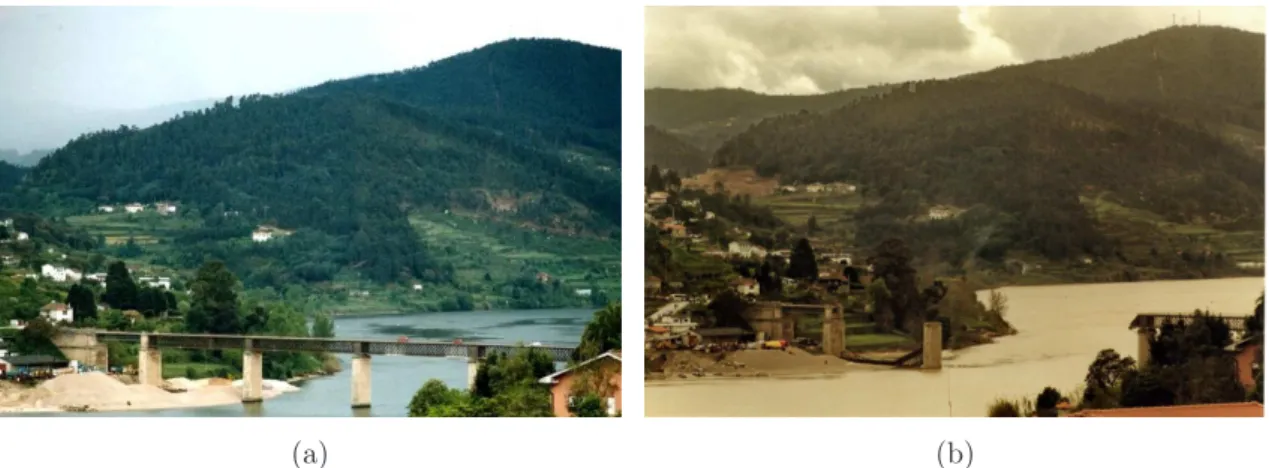
2.12 Penacova bridge, 1975 (adapted from EP-Estradas de Portugal (2012)). (a) Bridge just after the pier settlement; (b) Retrofitted bridge with external cables. . . 20
2.13 I-35W Mississippi River bridge collapse, Minneapolis, 2007 (adapted from NTSB (2008)). . . 21
2.14 Gusset plate used to unite multiple structural members of a truss (adapted from NTSB (2008)). . . 22
2.15 Progressive loss in structural function. . . 23
2.16 Tree of events leading to structural failure, from exposure to consequences. 24
2.17 Structural threats classification according to Bontempi et al. (2007). . . 25
2.18 Gas explosion in reinforced concrete buildings in Portugal: (a) Set´ubal (adapted from Duarte (2009)); (b) Lisboa (adapted from Martins (2011)). . 29
2.19 Robustness: structural propertyvs. property of structure and environment. 33
2.20 Classification of several proposed robustness measures. . . 36
2.21 Truss system undergoing damage of one member (adapted from Biondini and Restelli, 2008). . . 38
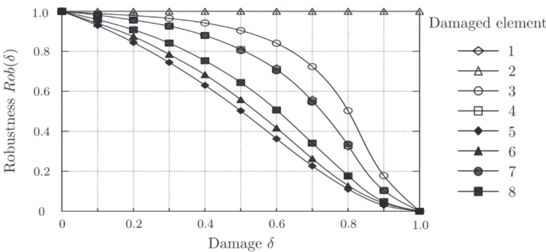
2.22 Results using displacement and considering the deterioration of all members each at a time (adapted from Biondini and Restelli, 2008). . . 39
2.23 Impact type of progressive collapses (adapted from Starossek (2009a)): (a) pancake-type; (b) domino-type. . . 40
2.24 Tacoma bridge collapse (adapted from Starossek (2009a)). . . 41
2.25 Second damage based robustness measure as proposed by Starossek, 2009b. 42
2.26 Normalized structural performance,f, as a function of normalized damage
d. (a) Minimum robustness; (b) intermediate robustness; (c) maximum robustness. . . 51
2.29 Normalized cross section area and inertia as a function of the corrosion depth. 54
2.30 Normalized performance depending on normalized damage. . . 55
2.31 Truss structure and bars cross section. . . 55
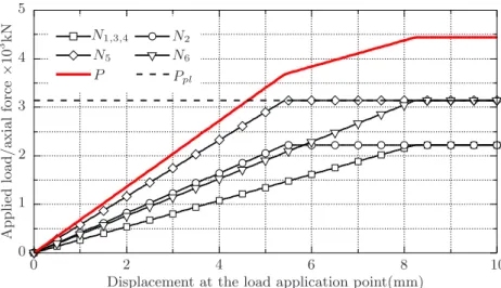
2.32 Applied load P, and axial force on frame elements,Ni, depending on
dis-placement, for the uncorroded structure. . . 57
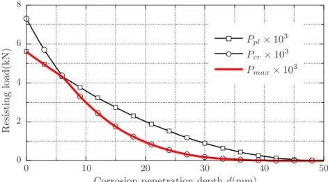
2.33 Maximum applied load,Pmax, as a function of the corroded bar and
corro-sion depth. . . 57
2.34 Normalized performance as a function of the corrosion level. (* 0.5Pmax(0)
is considered as the minimum acceptable load carrying capacity) . . . 59
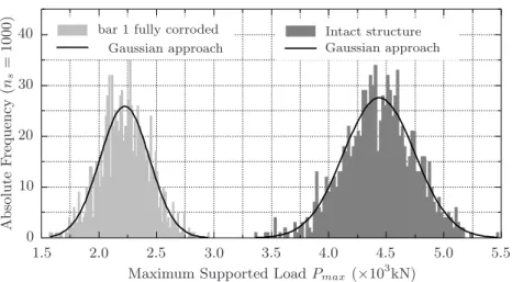
2.35 Maximum supported load, Pmax, histogram for a sample size ns = 1000,
and respective Gaussian approach . . . 60
2.36 Structure reliability index,β, and failure probability,Pf, depending on the
corroded bar and on the corrosion penetration depth. . . 61
2.37 Normalized reliability and failure probability as a function of the normalized damage . . . 62
3.1 Corrosion electrochemical process (adpated from PCA (2013)). . . 66
3.2 Initiation and propagation stages during structure lifetime (adapted from Tuutti (1982)). . . 68
3.3 Carbonation ingress (adapted from PCA (2013)). . . 69
3.4 Corrosion microcells in a generalized corrosion case (adapted from Pina (2009)). . . 71
3.5 Cathodic an anodic region in a pitting corrosion case (adapted from GOTECH (2013)). . . 72
3.8 Steel bars area lost depending on diameter (adapted from Rodriguez et al.
(1996)). . . 75
3.9 Iron oxides relative volume (adapted from Roberge (2000)). . . 76
3.10 Cracking and spalling due to corrosion (adapted from Pina (2009)) . . . 76
3.11 Bond stress versus slip relation developed at the interface (adapted from CEB (1993)). . . 80
3.12 Qualitative variation of bond strength with corrosion (adapted from FIB (2000)). . . 82
3.13 Changing in structural behavior due to reinforcement disbonding: (a) clas-sical Morsch’s truss; (b) bottom reinforcement disbonded with functional anchorages (c) completely disbonded reinforcement and anchorages. . . 88
3.14 Pronounced corrosion on a connection between longitudinal and transversal girder on a bridge deck (adapted from Jacinto et al. (2011). . . 89
3.15 Corrosion analysis methodology proposed by S´anchez et al. (2010): (a) cross section analysis; (b) longitudinal structural analysis. . . 90
3.16 Comparison between results on corroded beams obtained experimentally by Rodriguez et al. (1994) and numerically by Coronelli (1997) and S´anchez et al. (2010) (adapted from S´anchez et al. (2010)). . . 91
4.1 Corrosion analysis methodology . . . 96
4.2 Equilibrium of a damaged section. . . 97
4.3 Isotropic Continuum Damage Model (adapted from Oliver (2000)). . . 99
4.4 Material hardening and softening. . . 100
4.5 Continuum Strong Discontinuity Approach (adapted from Oliver and Hue-spe (2004)). . . 101
model; (d) tangencial stresses constitutive model. . . 104
4.8 Cross sections under corrosion analysis: (a) Flat slab design; (b)I-beam design. . . 105
4.9 Damage on concrete due to corrosion. . . 106
4.10 Damage on the flat slab due to steel bar expansion. . . 108
4.11 Cracking pattern on the flat slab. . . 109
4.12 Crack width as a function of the corrosion penetration depth,X, and of the corrosion level on bottom,XP1, and top,XP2, reinforcement, . . . 109
4.13 Bottom cracks width as a function of the corrosion level on the bottom reinforcement,XP1. . . 110
4.14 Top cracks width as a function of the corrosion level on the top reinforce-ment, XP2 . . . 111
4.15 Damage on concrete due to corrosion for the I-beam solution. . . 112
4.16 Damage on the I-beam due to steel bar expansion. . . 113
4.17 Cracking pattern on the I-beam. . . 114
4.18 Crack width as a function of the corrosion penetration depth,X, and of the corrosion level on bottom,XP1, and top,XP2, reinforcement, . . . 115
4.19 Bottom cracks width as a function of the corrosion level on the bottom reinforcement,XP1. . . 116
4.20 Top cracks width as a function of the corrosion level on the top reinforce-ment, XP2 . . . 116
4.21 Composite material model (Oliver et al., 2008b). . . 118
4.22 Composite material model components (adapted from Oliver et al., 2008b). 119 4.23 Slipping-fiber model. . . 120
4.26 Normalized bond strength as a function of corrosion level for experimental data of pull-out tests (adapted from Bhargava et al. (2007)). . . 123
4.27 Structural model. . . 124
4.28 Two dimensional finite element model for the flat slab. . . 125
4.29 Two dimensional finite element model for the I-beam. . . 126
4.30 Load displacement diagram for the flat slab and the I-beam. . . 126
4.31 Damage map on concrete for the flat slab for points 1 to 5 on the load displacement diagram. . . 128
4.32 Damage map and iso-displacement contour lines respecting to the failure mechanism. . . 129
4.33 Horizontal displacement at the slab cross section bottom fiber. . . 129
4.34 Damage map on concrete for the I-beam for points 1 to 5 on the load displacement diagram. . . 131
4.35 Damage map and iso-displacement contour lines respecting to the failure mechanism. . . 132
4.36 Horizontal displacement at the I-beam cross section bottom fiber. . . 132
4.37 Coupling both cross section and longitudinal analysis for the flat slab. . . . 134
4.38 Coupling both cross section and longitudinal analysis for the I-beam. . . 135
4.39 Load-displacement diagram as a function of the corrosion level for the flat slab. . . 136
4.40 Load-displacement diagram as a function of the corrosion level for the I-beam.137
4.41 Normalized peak load carrying capacityF/Fmaxand normalized bond strength σiy(XP)
σi
y(Xp= 0)
as a function of the corrosion level XP. . . 138
4.42 Normalized peak load carrying capacity F/Fmax as a function of the
nor-malized bond strength deterioration Dσi
4.44 Normalized peak load carrying capacity F/Fmax for the flat slab as a
function of the corrosion level, XP, regarding the effects of: curve
(a)-reinforcement area reduction, disbonding and concrete cracking; curve (b)-reinforcement area reduction and disbonding; curve (c)-(b)-reinforcement area reduction and concrete cracking; curve (d)-reinforcement area reduction. . . 142
4.45 Normalized peak load carrying capacityF/Fmaxfor the I-beam as a function
of the corrosion level,XP, regarding the effects of: curve (a)-reinforcement
area reduction, disbonding and concrete cracking; curve (b)-reinforcement area reduction and disbonding; curve (c)-reinforcement area reduction and concrete cracking; curve (d)-reinforcement area reduction. . . 144
4.46 Normalized peak load carrying capacityF/Fmaxand normalized bond strength σyi(XP)/σiy(XP = 0) as a function of the corrosion level XP. . . 146
5.1 Building floor subjected to people concentration load. . . 150
5.2 Structural model. . . 151
5.3 Cross Section. . . 151
5.4 Cross Section finite element model (4864 triangular elements). . . 152
5.5 Structural finite element model (6796 triangular elements). . . 153
5.6 Concrete damage map on beam’s cross section due to steel bar expansion. . 154
5.7 Damage and cracking on beam’s cross section due to steel bar expansion. (a) Damage d, for XP1 = 10%, XP2 = 20%; (b) Iso-displacement contour
lines; (c) Cracking pattern; (d) Effective cross section. . . 155
5.8 Cross section cracks width as a function of the corrosion depth, X, and levels,XP1 and XP2 . . . 156
5.9 Load displacement diagram for the uncorroded structure . . . 156
5.12 First crack width opening depending on the corrosion level. . . 159
5.13 Computing average damage on cross section: (a)damage on the cross sec-tion; (b) section core; (c) equivalent damage distribusec-tion; (d) average dam-age on section height. . . 159
5.14 Transferring average damage from the cross section to the longitudinal model: (a) average damage on the cross section; (b) initial damage on the 2D longitudinal model. . . 160
5.15 Resisting load as a function of the corrosion level. . . 161
5.16 Robustness assessment of the RC beam under corrosion. . . 162
5.17 Reliability analysis flowchart. . . 167
5.18 Support points at the design point neighborhood. . . 168
5.19 ”Flood algorithm”: (a) 1st step; (b) Intermediate step; (c) Last step; (d) Final concrete damage map. . . 169
5.20 Reliability index,β, and failure probability,Pf, as a function of the
corro-sion level, XP. . . 170
5.21 Normalized reliability indexβ(XP)/β(0) as a function of the corrosion level, XP, regarding the effects of: curve (a)-reinforcement area reduction,
dis-bonding and concrete cracking; curve (b)-reinforcement area reduction and disbonding; curve (c)-reinforcement area reduction and concrete cracking; curve (d)-reinforcement area reduction. . . 171
5.22 Design point,dp coordinates on the normalized space as a function of the
corrosion level,XP, respecting to curve (a) in Figure 5.21. . . 173
5.23 Design point,dp coordinates on the normalized space as a function of the
corrosion level,XP, respecting to curve (b) in Figure 5.21. . . 173
5.24 Design point,dp coordinates on the normalized space as a function of the
corrosion level,XP, respecting to curve (c) in Figure 5.21. . . 173
5.25 Design point,dp coordinates on the normalized space as a function of the
6.3 Bridge deck cross section at middle span and at the supports (adapted from Jacinto (2011)). . . 179
6.4 Corrosion affecting girders 1 to 4 (adapted from Jacinto et al. (2011)). . . . 181
6.5 Exposed reinforcement on girder 1 (adapted from Jacinto et al. (2011)). . . 182
6.6 Opensees frame finite elements model. . . 183
6.7 Opensees cross section models used for the deck girders at the central span, top slab and crossbeams: (a) cross section at middle span of lateral gird-ers; (b) cross section at middle span of internal girdgird-ers; (c)cross section at supports of internal girders; (d) cross section at supports of lateral girders; (e) top slab section; (f) cross beam cross section. . . 184
6.8 Linear tension and compression softening constitutive relation of concrete (adapted from Yassin (1994)). . . 185
6.9 Traffic loads according to CEN (2002a). . . 186
6.10 Partial safety factor for traffic loads as a function of the displacement mea-sured in the middle span section of girders 1 to 4 in the central span, considering reinforcement intact and corroded. . . 188
6.11 Intact girders reinforcement stresses as a function of the traffic loads safety factor, measured in: (a) top reinforcement in section above supports in Girder 1; (b) bottom reinforcement in middle span in Girder 1; (c) top re-inforcement in section above supports in Girder 4; (d) bottom rere-inforcement in middle span in Girder 4; . . . 189
6.12 Maximum partial safety factor for traffic loads as a function of the corrosion level on girder 1. . . 191
6.13 Girders vertical reaction over piers versus the partial safety factor for traffic loads considering:(i) uniform corrosion among girders, XP2,3,4 = XP1; (ii)
girder 2 to 4 as uncorroded,XP2,3,4 = 0. . . 192
6.16 Axial force near failure on deck girders for case (a),XP1,2,3,4 = 100%. . . 194
6.17 Axial force near failure on deck girders for case (e),XP2,3,4 = 0 and XP1 =
100%. . . 194
6.18 Normalized safety factor for the traffic loads as a function of corrosion level on girder 1. . . 195
6.19 Reliability analysis flowchart. . . 201
6.20 Reliability index as a function of the corrosion level. . . 202
3.1 Summary of tests on corrosion related to cracking of concrete cover (adapted from FIB (2000)). . . 78
3.2 Summary of tests on bond strength of corroded reinforcement. . . 81
3.3 Summary of tests on strength of beams and slabs with corroded reinforcement. 85
4.1 Concrete Material Properties. . . 104
4.2 Flat slab robustness assessment. . . 143
4.3 Relative importance, ri, of corrosion effects on performance decreasing of
flat slab. . . 143
4.4 I-beam robustness assessment. . . 145
4.5 Relative importance, ri, of corrosion effects on performance decreasing of
I-beam. . . 145
5.1 Robustness assessment. . . 162
5.2 Random variables distributions and parameters. . . 165
5.3 Robustness assessment. . . 172
6.1 Tercenas bridge robustness assessment. . . 195
6.2 Random variables distributions and parameters. . . 198
6.3 Tercenas bridge robustness assessment. . . 204
Introduction
1.1
Motivation
In the recent past, the occurrence of catastrophic consequences due to extreme events on buildings and bridges has increased the interest of the scientific community in structural robustness (Frangopol and Curley, 1987; Lind, 1995; Ghosn and Moses, 1998; Baker et al., 2008; Starossek and Haberland, 2008; Cavaco et al., 2013).
Events, such as the collapses of the Alfred P. Murrah Federal Building in Oklahoma City (1995), the World Trade Center in New York (2001), the Windsor Tower in Madrid (2005) and the I-35W Mississippi River bridge in Minneapolis (2007), among others, have awaken the interest of engineers in this concept.
Although, the referred collapses had different causes, such as the occurrence of a fire, a terrorist attack, or component failure, among others, the fact is that in all the cases the consequences resulting from collapse were considered disproportionate in relation to the initial damage. This idea became particularly clear after 9/11 since the consequences due to structural failure largely supersede the mere rebuilding costs by order magnitudes.
On the other hand, the need for a robustness framework has also arisen from the fact that structural design codes are based specially on the design of structural members individu-ally, neglecting, in most cases, the overall structural performance.
structural robustness is not well defined and understood, and much controversy still per-sists on this subject.
At a first sight, robustness seems to be a more interesting concept in scenarios where structures are subjected to unforeseen events and where huge consequences may be ex-pected. However robustness can also be very useful in more probable damage scenarios such as those resulting from the predictable usage and design exposures or even from de-terioration. In fact, the analysis of several extreme structural collapses showed a relevant influence of aging and deterioration. On the other hand, most developed countries have built networks of infrastructures with vital social and economic importance. Significant structural deterioration has been detected specially in transportation networks, and con-siderable investments are needed to keep these infrastructures safe and serviceable. This is particularly true for reinforced concrete structures where damage resulting from steel corrosion is the paramount factor causing safety decreasing. In this manner, the identi-fication of robust existing structures is crucial for managing these infrastructures, as it provides critical information required to optimize the time of application of maintenance actions. At the same time, the identification of the robust character of some structural types can also be very useful to plan and design future infrastructures.
Significant research has focused on understanding the corrosion mechanism in detail (Tu-utti, 1982; Schiessl, 1988; Broomfield, 1996; Roberge, 2000; Fontana, 2005). It seems clear that this is a very complex mechanism, depending on a large amount of highly variable factors (concrete and steel grade, cover thickness, crack width, etc.) and conditions (at-mosphere chemical compounds, temperature, humidity, electrical potential, wind, stress levels etc.). Consequently, corrosion is extremely hard to predict accurately, both in time and in space. Therefore, a probabilistic approach may result more attractive.
Less research has been dedicated to the safety assessment of corroded structures, in partic-ular because it is difficult to reproduce corrosion and its deteriorating effects in a controlled experimental environment. However, some authors (Kawamura et al., 1995; Almusallam et al., 1996b; Rodriguez et al., 1997; Mangat and Elgarf, 1999; Saetta, 2005; Torres-Acosta et al., 2007; Pina, 2009) have tried to establish a relation between the corrosion and per-formance levels on reinforced concrete structures. This could be particularly interesting for existing structures when an update of the current safety levels need to be performed.
and deterioration.
In this manner, this thesis intends to present a clear analysis of the robustness concept, establishing a unique and an innovative framework to assess it. Special focus is given to corroding reinforced concrete structures as this construction type is present in a significant fraction of the aged structures across Europe and in particular in Portugal.
The methodology presented here intends to guide the search for existing structural typolo-gies more tolerant to corrosion, in order to optimize the investment priorities in mainte-nance and repair of existing infrastructures. Additionally, the methodology propose here can also assist the planning and design of future infrastructures requiring less investments in maintenance and repair actions during the exploration period.
1.2
Contributions
This thesis includes the following contributions:
a state of art on structural robustness describing and analyzing the wide range of per-spectives and approaches proposed over the last two decades. Several author’s defi-nitions and measures for robustness are analyzed, discussed in detail and compared. Robustness indicators include both deterministic and probabilistic approaches for robustness, as well as, risk perspectives. This analyzes serves as foundation for the developed work but, at the same time, contains an innovative general overview of the research done in this topic;
a new framework to assess robustness, since those already proposed in the literature were in general more oriented to describe the consequences of extreme events on structures. In this thesis a new definition for robustness, based on a structural perspective, is proposed. Also a multipurpose robustness indicator is established. This indicator is based on the proposals found in the literature, and it is developed to solve the most important recognized shortcomings, in particular those related with structural aging and deterioration. However, the proposed indicator is sufficiently generic to be applied in different damage scenarios and different types of structures;
corrosion analysis, including these effects, is defined. The analysis is based on the methodology proposed by S´anchez et al. (2010) with some improvements such as the update of the bond strength degradation law (depending on the corrosion level) and the use of the mixture theory to model reinforced concrete in order to reduce computational costs;
deterministic and probabilistic robustness evaluations of different reinforced concrete structures subjected to corrosion. Using the proposed methodologies to assess ro-bustness and corrosion effects, a roro-bustness evaluation of different structural types, including an existing structure is performed. Depending on the structural perfor-mance indicator used, this evaluation may result either deterministic or probabilistic. Robustness assessment, as defined in this thesis, gives a measure of the structure tolerance to corrosion. The methodology used to assess robustness also depicts the relative importance to the final result of several factors such as the cross section geometry, the effects of concrete cracking and bond strength deterioration, among others. The proposed methodology is generic enough to be suitable of application in other damage and exposure scenarios.
1.3
Thesis Organization
Beyond Chapter 1 this thesis is organized in the following form: in Chapter 2 a literature review on robustness is presented. Some examples of structures, where the lack of robust-ness was recognized, are analyzed. Several author’s definitions for robustrobust-ness are presented and discussed. Special emphasis is given to the fact that some authors define robustness as an intrinsic structural property while others consider it as a property of the structure and its environment. Some related and sometimes mistaken concepts are presented and discussed. The most important proposed measures for robustness are also presented in-cluding some illustration examples. Finally a comparison between them is made and the respective shortcomings are identified. This may help understanding the reason for the lack in consensus on the robustness area. After a deep analysis of the robustness nature, a new structural oriented definition is proposed. Based on the highlighted shortcomings of the existing measures, in particular those related with the application to deteriorated structures, a unique framework for robustness assessment is proposed. This new approach is illustrated by means of simple application examples, and compared with the existing measures.
mechanisms resulting from reinforcement corrosion are described with reference to exper-imental research works in this topic. Special focus is placed on experiments respecting to the evaluation of the load carrying capacity of deteriorated reinforced concrete structures. An approach to the most important numerical modeling techniques, to assess the loading carrying capacity and safety of deteriorating structures, is also made.
Chapter 4 focus on the corrosion analysis methodology that includes the most concerning deteriorating mechanisms, beyond the reinforcement area reduction, such as the concrete deterioration and cracking, due to the expansion of oxidation sub products, and the dete-rioration of bond between reinforcement bars and the surrounding concrete. Attention is paid to some advanced numerical techniques, such as the continuum strong discontinuities approach used to enrich the kinematics of the finite elements, which allow concrete crack-ing numerical simulation. A deterministic application of the proposed robustness measure is firstly presented, consisting in a simply supported foot bridge subjected to uniform cor-rosion of longitudinal reinforcement. Two cross section designs, with different slenderness, are analyzed and compared and the obtained results are discussed.
In Chapter 5 the proposed methodology is probabilistically updated. A smaller example, consisting on a simply supported reinforced concrete beam, is presented, due to compu-tational effort required to compute a combined corrosion-reliability analysis. The most important random variables with influence on the structural safety are characterized, in particular their distribution function, mean value and standard deviation. The reliability techniques used, as well as it integration together with the corrosion analysis, are analyzed in detail. The First Order Reliability Method (FORM), combined with the Response Sur-face Method and the corrosion analysis method presented in Chapter 4, is used to predict the reliability and robustness of the presented example when subjected to reinforcement corrosion. Based on the obtained results, the tolerance to corrosion of the reinforced con-crete beam is discussed, as well as the relative importance of the several deteriorating effects resulting from corrosion.
tolerance to corrosion including the existing safety levels at the moment of its demolition are analyzed and discussed.
Structural Robustness
2.1
Introduction
The concept of structural robustness has received an intermittent interest in the last 40 years, specially due to occurrence of some extreme events in buildings and bridges with catastrophic consequences. The lack of structural robustness has been claimed as the major cause of those accidents, but in fact, the concept essence has never been accurately defined. Terrorist attacks, explosions, floods, severe human errors, among others, are examples of exposures that can trigger a sudden global failure. These are rare events with almost no similarities between them, which produce unique and complex demanding actions on structures. In this manner, and having in mind that no clear definition for robustness exists, it has been hard to establish practical rules and procedures that might help engineers in designing and building structures capable of sustaining extreme events without catastrophic consequences.
In the last 20 years, most developed societies have been facing the problem of infrastructure aging. The needs for maintenance already represent a significant fraction of governments investments in infrastructures (Neves and Frangopol, 2005). In spite of these investments, the analysis of the causes of several structural collapses (Lichtenstein, 1993; Cooper and Munley, 1995; Woodward, 1989) showed a significant influence of deterioration. In this manner, although the concept of robustness has been typically related with extreme events, it can also be useful when used in the context of structural aging.
based on the respective investigation report, the causes of failure and the resulting con-sequences will be discussed in an attempt to understand what could have been done to avoid failure or limit consequences.
The most relevant definitions of robustness, proposed by different researchers, will also be discussed, in an attempt to understand the true nature of the robustness concept. In the same manner, the most significant attempts to quantify structural robustness will be presented and related with the proposed definitions. Based on these, an original proposal for a framework to define and quantify robustness is made. Although sufficiently generic, the proposal made is oriented to the analysis of deteriorating and aging structures. Finally, several practical examples, depicting the use of the proposed robustness framework, will be presented.
2.2
Introductory examples
In the next sections several cases of buildings and bridges failures, for which structural robustness was widely discussed, will be presented.
2.2.1 Building failure examples
2.2.1.1 Ronan Point apartment tower collapse, London, 1968
The Ronan Point tower construction was completed on 11 March 1968, based on the Larsen-Neilsen constructing system developed in 1948, in Denmark, for buildings under six stories (see Figure 2.1) (Pearson and Delatte, 2005). This system consists on the assembly of precast concrete elements including walls, floors and stairways. Each wall and floor panels were linked together using bolted joints filled with dry-pack mortar (see Figure 2.2) (Pearson and Delatte, 2005).
In the morning of May 16th, 1968, two months after the conclusion of construction, in the kitchen of 18thfloor of the 22-story building, a resident lit a match that produced a small explosion, due to a gas leak (Pearson et al., 2003), initiating a partial progressive collapse upward and downward through the corner of the building (see Figure 2.1). The partial collapse of the structure resulted in 4 casualties, 17 injured, significant repair costs and a delay in new social housing projects in the United Kingdom (Pearson and Delatte, 2005).
Figure 2.1: Ronan Point, London, 1968 (adapted from MacLeod (2005)).
corner walls of the apartment. These walls were the only support of 19th floor and the walls directly above. Therefore, a chain reaction was initiated propagating floor by floor upward until the 22thfloor. The weight of these four floors fell onto the 18thfloor initiating a second chain of failures towards the ground level.
Bignell et al. (1977) estimated the intensity of the explosion based on its particular damage to hearing, and concluded that it was relatively low, resulting in a pressure on the walls lower than 70kPa. This estimate was supported by the analysis of several damaged objects taken from the 18th floor apartment’s kitchen. Research presented by Levi and Salvadori (1992) on the resistance of the walls, used in the Ronan Point structure, revealed that they could only sustain an internal pressure of no more than 19.3kPa. Griffiths et al. (1968) estimated this resistance to be 21kPa. The same researcher also suggested that these pressure magnitudes could result from moderate winds.
(a) Schematic design of joint (b) As built joint
Figure 2.2: Exterior horizontal joint between floor slab and flank wall (adapted from Pearson and Delatte (2005)): (a) schematic design of joint; (b) as built joint.
were placed on bolts instead of mortar; and crucial joints between walls and floors had, in some cases, less than fifty percent of the specified mortar (see Figure 2.2).
These findings completed the investigation about the reasons leading to Ronan Point tower partial collapse. It became clear that, although connection between walls and floors were crucial for structural safety, these components were poorly designed. The situation was aggravated as a result of serious and frequent errors during construction, due to overall poor workmanship. Moreover, the Larsen-Neilsen system does not present a significant capacity to develop alternative load paths, increasing the consequences of both design and construction errors. In short, the building can be described as a ”house of cards” (Levi and Salvadori, 1992).
2.2.1.2 World Trade Center, New York, 2001
Figure 2.3: September 11 in New York, USA, 2001 (adapted from Thomas (2011)).
has resisted a prior bombing attack on February 26, 1993. A truck bomb was detonated on the parking garage below the North tower with the intention of causing it to collapse over the South Tower, resulting in the collapse of both towers. The attack was not successful but 6 people died and more than a thousand got injured.
The World Trade Center towers were designed and built in the mid-1960s through the early 1970s. Each tower was designed as a cantilever standing 411m above the street level and 21m below. At the ground level, the tower cross section was a square with 64m side (Eagar and Musso, 2001). The buildings were designed to sustain the expected gravity loads (dead and live loads), lateral loads resulting from hurricane winds and even the impact of a Boeing 707.
Figure 2.4: World Trade Center exterior wall (adapted from NCSTAR (2005)).
on the building’s top. The ”hat truss” was designed to sustain an antenna at each tower top. However it had an additional role of connecting both exterior wall and core columns providing extra load redistribution between the two structural subsystems.
and, during the floor collapse, it acquired a huge amount of kinetic energy and a significant downward velocity. When this part of the building impacted the underlying structure it far exceeded its load carrying capacity, leading also to its failure. This initiated a chain reaction of floors collapsing towards the ground level. The final result was a huge amount of wreckage with an average height of about 8% of the towers size.
Although a tremendous number of lives was lost (2606 within the towers and on the ground), 87% of the estimated 17400 occupants (NCSTAR, 2005) were evacuated success-fully. However, this may have been a consequence of the low occupancy of the buildings at the time of the attack (only one-third to one-half of the total occupants were in the buildings). Regard that evacuation capacity required by actual building codes is deter-mined by single floor calculation not having in consideration the overall building height. This may have had a significant impact on the evaluation of the towers robustness (i.e., consequences were huge but could have been even worse). On one hand, the towers struc-tures were sufficiently resilient to allow the evacuation of a considerable percentage of the occupants. However this may only had happened since the buildings were less than 50% occupied. On the other hand, it seems widely accepted that this tragic event changed the world and that its consequences are far to be known and accounted for. In this manner, and having in mind that a definitive definition for robustness still does not exist, it is acceptable that the World Trade Center towers have been widely considered robust but also the opposite. The question sometimes is not if the towers should have been built differently, but if they should have been built at all.
2.2.1.3 Bad Reichenhall arena, Germany, 2006
The Bad Reichenhall ice-arena, built in 1972, covered a sports area of approximately 75m in length by 48m in width (see Figure 2.5).
The roof was supported by 2.87m high main box girders, which were produced in timber. The box-girders were composed by upper and lower glulam girders and lateral web boards built in a type of X-lam panels (see Figure 2.6). The 48m long girders were produced out of three 16m long sections, which were joined using finger joints. Transversely to the main girders, a secondary structural system acted as purlin and bracing system, simultaneously. This system was relatively stiff allowing load redistribution between the main girders.
(a) (b)
Figure 2.5: Bad Reichenhall ice-arena (adapted from Winter and Kreuzinger (2008)). (a) Prior to collapse; (b) After collapse.
Lateral view Transversal section(hh) Transversal section(gg)
Longitudinal cut(II)
Legend c-upper girder d-lower girder h-web-board k-purlin
g-reinforcement (to avoid buckling)
Second World War.
According to the evaluation ordered by the public prosecutor, several reasons were in the origin of the arena collapse (Winter and Kreuzinger, 2008). The web boards building height was superseded for this type of construction. A general technical approval was available at the time, limiting the height the web-girders produced in this manner to 1.20m. The static calculation of the roof structure was not checked by an experienced engineer, as defined by law in Germany, for this building class. According to the investigation report (Winter and Kreuzinger, 2008), the load bearing capacity of the main girders was over-assessed and the effect of both joint fingers and moisture was neglected. These errors and omissions resulted in a significant over-assessment of the static load-bearing behavior of the roof. The necessary structural safety margin of, at least, 2.0 did not exist. Parallel calculation suggested a safety margin of 1.5 at the time of collapse (Winter and Kreuzinger, 2008).
Experts also found that urea-formaldehyde glue had been used to build the main box-girders. Since this glue is sensible to moisture, its use for load-bearing components was only admissible in dry environments, according to the existing technical rules at the time. However, relative humidity is generally very high in ice arenas and condensation is likely to occur on the underside of the roof structure. Additionally, several cases of water infiltration and poor maintenance were detected in the roof of the Bad Reichenhall arena.
According to the experts, the collapse began with the failure of one main girder at the east end of the arena. Due to the stiff cross girders, the loads were shifted from the girder that failed first to the neighboring girders. These box-girders, which were already impaired, were also overloaded, resulting that the entire roof collapsed like a zipper.
Robustness has been widely related with redundancy and with the ability of the structure to develop alternate load path. Structural redundancy, in the case of the Bad Reinchenhall arena, caused a chain reaction of girders failing until the full collapse was achieved. This shows that redundancy alone cannot be used as a measure of robustness for all structures.
2.2.1.4 Siemens arena, Denmark, 2001
A similar accident occurred in the cycling Siemens arena in Denmark in 2001 (see Figure 2.7). In fact, the Siemens arena structure was very similar to the Bad Reichenhall arena structure, but fortunately, in this case, no fatalities were registered.
Figure 2.7: The Siemens Arena structure after collapsing. Intact truss on the right (adapted from Munch-Andersen and Dietsch (2011)).
Figure 2.7. Each truss was simply supported at the extremities resulting in the compression and tension of the upper and lower arches, respectively. The horizontal components of both compression and tension forces were neutralized at the corners connections with concealed steel plates, connecting the timber parts of both arches through bolts and dowels as shown in Figure 2.8 (a). In contrast to the case of the Bad Reinchenhall arena, here, the secondary structural subsystem of purlins was simply supported on the main trusses.
As shown in Figure 2.7 the collapse of the Siemens arena roof involved 2 of a total of 12 main trusses. In this case progressive collapse was prevented since purlins were only moderately fastened to the main girders.
According to the investigation (Munch-Andersen and Dietsch, 2011) failure was due to an insufficient strength of a critical cross section localized in tension arch near the support (see Figure 2.8 (b)). It was found that the critical section had between 25% and 30% of the required strength. This resulted in partial roof collapse under relative low loading conditions (no wind and only a few snow milimeters).
The main girders strength deficiency was related to three critical design errors: a 48% too high design strength for the timber parts; an insufficient cross section height near the arches end; and the reduced timber cross section on the connection zone due to steel plates, bolts and dowels.
(a) (b)
Figure 2.8: Siemens arena main truss connections (adapted from (Munch-Andersen and Dietsch, 2011)): (a) corner connection with concealed steel plates, connecting the timber parts through bolts and dowels; (b) failure at the critical cross section in the corner connection.
the Bad Reichenhall arena, the collapse extent was limited since the secondary subsystem was only simply supported on the main girders. In the Bad Reichenhall arena the initial strength lack was much smaller but was developed over time. Local damages were never visible since the stiff purling system allowed load transfer between main girder without excessive deformations. In this manner, the collapse occurred under more severe loading conditions. Probably, the structure degradation and local damages could have been issued if a less stiff purling system had been used.
2.2.1.5 Residential building in Coimbra, Portugal, 2000
In January 3rd, 2000, a landslide occurred in Coimbra, Portugal, causing severe damage in the reinforced concrete structure of a 16-story residential building, built in the beginning of the 1980s (see Figure 2.9). The first two levels of three columns were completely destroyed and, as a result, the rear body of the building supported by these, with a dimension in plant of 9.5×6.5m2, became a 7.0m span cantilever with 12 stories. The damage could have been even worse if the flow of soil had not been damped by part of the 2-story parking garage located on the building’s backyard that completely vanished (Tiago and Julio, 2010). Surprisingly the building did not collapsed and it was evacuated without fatalities.
(a) (b)
Figure 2.9: Residential building in Coimbra, Portugal, damage by a landslide occurred in January, 2000 (adapted from Tiago and Julio (2010)): (a) rear facade of the building a few days after the accident; (b) detail of the total collapse of the outer columns.
resulting in a strut and tie system that resisted the gravity loads. In the damaged part of the building, the loads previously supported by the destroyed columns became equilibrated by compression stresses (struts) at the outer masonry walls and by tension stresses (ties) at the slabs (see Figure 2.10). In the remaining part of the building, this system originated: a tension resultant force at the top slab; a compression resultant force at the bottom slab; and an additional compression at the existing foundations (see Figure 2.10).
This case contrasts with the case of the Ronan Point tower. In this case, the type of structural system used, in conjunction with the non-structural partition walls, was able to develop an alternate load path, avoiding collapse, even when highly damaged.
2.2.2 Bridges failure examples
2.2.2.1 Hintze Ribeiro bridge, Portugal, 2001
strut tie
Figure 2.10: Schematic drawing of the strut and tie system developed after the accident (adapted from Tiago and Julio (2010)).
Hintze Ribeiro bridge, built in 1888, had a total length of about 300m divided in five inner spans of 50m and two external spans of 25m. The bridge deck inner spans were composed by a continuous steel truss supported on piers placed at the river bed. The external spans consisted also on steel trusses but were simply supported on piers and abutments placed at the river margins. Piers were built using granite masonry and founded on steel boxes filled with grouted masonry. As shown in Figure 2.11, the partial collapse of the bridge involved an inner pier and the respective supported spans plus an adjacent span.
According to the investigation report (Correia et al., 2001) the collapse was caused by insufficient foundation of the steel box supporting the failed pier. The deterioration of the load carrying capacity of the steel box was related to a decrease in the river bed profile, reaching 28m in the some places. Underwater inspections carried out between 1986 and 1988 already have denoted relevant erosion of the river bed profile near the columns foundation. However, these results were not alarming enough to lead to repair.
(a) (b)
Figure 2.11: Hintze Ribeiro bridge over the Douro river, in the north of Portugal (adapted from Leit˜ao (2011)): (a) before the collapse, 2000; (b) after the collapse, 2001.
2.2.2.2 Penacova bridge, Portugal, 1975
A similar situation had occurred some years earlier with the Penacova bridge, also in Portugal, fortunately with less tragic consequences. The incident is not well documented, but in the year of 1975 a pier placed at the river bed suffered a serious settlement (see Figure 2.12 (a)). The bridge deck had a similar structure to the Hintze Ribeiro bridge, composed by a continuous steel truss with a top concrete slab, supported on masonry piers placed at the river bed and abutments at the river margins.
(a) (b)
Figure 2.12: Penacova bridge, 1975 (adapted from EP-Estradas de Portugal (2012)). (a) Bridge just after the pier settlement; (b) Retrofitted bridge with external cables.
In this case, after the pier settlement, the structure could sustain it self weigh long enough to allow retrofitting with an external pre-stressed cable, as shown in Figure 2.12 (b).
deck. Attending to the inclination angle (see Figure 2.12) and to the fact that piers were built on masonry, the support provided could only be residual.
These two very similar cases raise questions about the strategies that could be adopted to minimize consequences in case of collapse. Starossek et al. (2010) suggests that segmen-tal design could be effective in restricting the spread of collapse after the failure of one structural member. This would have been the case of the Hintze Ribeiro bridge, if spans were simply supported on piers. However, significant stiffness existed in the connection between spans, allowing the progression of failure beyond the directly affected spans. On the other hand, in the case of Penacova bridge, the deck continuity avoided the collapse after the pier settlement. In this case, if segmentation has been used, the adjacent spans to the settled pier would have certainly failed.
2.2.2.3 I-35W Mississippi River bridge, Minneapolis, 2007
In the afternoon of August 1st, 2007, the eight-lane and 629m long I-35W bridge, over the Mississippi River at Minneapolis, Minnesota, suffered an abrupt partial collapse of the middle span (see Figure 2.13).
On the day of the collapse, roadway work was underway. Four of the eight travel lanes were closed to traffic and some construction equipment and materials were spread in one of the closed lanes. The failure of the bridge resulted in 13 casualties and 145 injured. These consequences would have been higher, if all lanes were in service.
Figure 2.13: I-35W Mississippi River bridge collapse, Minneapolis, 2007 (adapted from NTSB (2008)).
-type trusses. The trusses were composed by welded box chords and ”H” shapes vertical and diagonal members (see Figure 2.14). Two riveted steel gusset plates connected five
Figure 2.14: Gusset plate used to unite multiple structural members of a truss (adapted from NTSB (2008)).
of these members (2 member chords, 2 diagonals and 1 vertical) at a joint, as shown in Figure 2.14. The two trusses were connected using bracing members, at the lower chord level, and with stringers supporting the floor, at the upper chord level.
After the bridge collapse, an in depth investigation was carried out, and, according to the resulting report (NTSB, 2008), the trigger event was a lateral shifting instability of a diagonal member and subsequent failure of the connector gusset plate, approximately at middle span of the deck truss. This damage led to truss failure, since the remaining members could not sustain the overload resulting from the joint failure. Since the deck was supported only by two trusses, the structural system was isostatic and therefore non redundant. This resulted in bridge middle span global collapse after the failure of one of the two supporting trusses.
The investigation team concluded that the cause of the accident was the failure of an improperly designed pair of gusset plates, which were overstressed by a substantial increase in the dead load from bridge modifications, and, on the day of the accident, the traffic load and the concentrated loads resulting from maintenance road works. The investigation also pointed out that, for 16 years prior to the accident, the National Bridge Inspection Standards rated this bridge as ”structurally deficient”. The excessive deformation of the gusset plates had been observed and reported. However, no action was taken, and the inspection procedure did not contribute to avoid the accident.
2.3
Collapse development
In the previous sections, several cases of accidents on structures were presented. For all, structural robustness, or related concepts, have been discussed. Although with no complete consensus, in some cases the structures have been considered robust while in others, the opposite was found. The scale of consequences has always played a role in this classification. Cases related with huge consequences have been always of more concern, independently of the structural behavior. However, without a concise and unequivocal definition for the robustness concept, it is not possible to have an objective discussion on which of the presented cases the structures lacked in robustness.
The first aspect that must be considered is that there are no risk free structures, and accidents and significant consequences are always possible. The limitation of risk must be seen as the main objective of the civil engineer, as will be discussed later.
Given a structure subjected to a hazard, some damage may occur depending on the type and magnitude of the hazard and the structural local resistance. This damage could lead to some local failure, or even system failure. Depending on the magnitude and characteristics of the performance loss, consequences may arise to both structure and its external environment and a new cycle may begin, leading to progressive loss in structural function and, in some cases, to global collapse (Figure 2.15).
Figure 2.15: Progressive loss in structural function.
sustain the floor directly above the destroyed walls. The failure of the stories above the 18th floor ended the first stage of structural disintegration and began a second one. The 18th floor collapsed over the 17th floor, initiating a second chain reaction of floors collapsing.
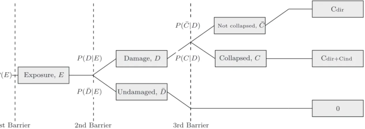
The event tree presented in Figure 2.16 and the probabilities associated with each event presented in Figure 2.15 can also help to understand the involved concepts and provide a global perspective of each step leading to the structural collapse.
Exposure,E
Damage,D
Undamaged, ¯D
Not collapsed,C¯
Collapsed,C
0 1st Barrier 2nd Barrier 3rd Barrier
P(E)
P( ¯D|E)
P( ¯C|D)
P(D|E) P(C|D) Cdir+Cind
Cdir
Figure 2.16: Tree of events leading to structural failure, from exposure to consequences.
Following the collapse branch in the event tree shown in Figure 2.16, the probability of collapse, P(C) can be computed as:
P(C) =P(E)×P(D|E)×P(C|D) (2.1)
whereP(E) is the probability of occurrence of an event susceptible of causing any damage on the structure; P(D|E) is the conditional probability of the structure being damage considering it is subjected to the exposure E; and P(C|D) is the collapse probability conditional on damage, D.
Considering the possible consequences of each case scenario in Figure 2.16, it is possible to obtain the associated risk. For the case where the structure becomes damaged after an exposure but does not collapse, only direct consequences for the structure itself are expected, Cdir. When the structure fails after being damaged, additional indirect
conse-quences,Cind, involving the structure surrounding environment must be accounted for.
2.3.1 Exposure prevention
The first alternative for reducing risk is associated with the minimization of the exposure probability, P(E). Exposure is defined herein as any event or threat potentially causing any damage or even the global failure.
According to Bontempi et al. (2007) threats to structures can be classified into physical and logical threats (see Figure 2.17). The first group can be divided into external faults and immanent faults. External faults could be extreme environmental actions (floods, earthquakes, hurricanes, etc.) and accidental actions or intentional explosion or impacts (fire, car, train or airplane impact, gas explosion, overloading etc.). Immanent faults are usually related to undetected defects such as material cracks or localized reduced strength. According to Bontempi et al. (2007), high probability events with less potential to damage, such as the one resulting from aging must also be considered.
The logical threats are those resulting from human errors during the design or the con-struction stage or even during the use period.
threats
physical
logical errors faults
failures immanent external
design construction usage
Figure 2.17: Structural threats classification according to Bontempi et al. (2007).
Of these exposures, few are within the area of intervention of civil engineers, and others (floods, earthquakes, among others) can hardly be limited. However, attempts to minimize the exposure probability,P(E), can be achieved by protecting the structure from threats. The preventive measures must be adequate to the expected exposure events, either ex-treme or abnormal. For example, in the case of the World Trade Center, minimizing the occurrence of such an event could be achieved by an increased X-scan control at airports, as occurred in the aftermath of the September 11th.
mea-sures can be taken to reduce the probability of early deterioration. One example could be reducing the use deicing salts spread over reinforced concrete structures, reducing the exposure to corrosion of reinforcement.
Logical threats are also difficult to avoid, since errors (during design, construction and usage stages) are inherent to human nature. However, such exposures can be reduced if, for instance, design check is adopted. Regard that one of the main conclusions suggested by experts that investigated the collapse of the Bad Reichenhall arena was that no verification was made to the calculation and design plans, although, for that class of building, this procedure was compulsory in Germany. Also, during construction, an accurate inspection of the works, specially on the critical stages, could have been very useful in minimizing the probability of the structure to be impaired.
Therefore, it is possible to reduce hazard exposure but it is not possible to completely eliminate it, specially since some threats have an accidental nature, thus cannot be pre-dicted.
2.3.2 Damage Prevention
Although exposure control is in general outside the structural engineering scope, struc-tures must be designed and built to sustain such exposures without being significantly damaged. In this manner, the second approach to reduce the probability of collapse aims at minimizing the conditional probability of the structure being locally damaged given a specific threat, P(D|E).
Current codes and standards focus on limiting this probability for expected threats (regular humans and traffic loads, snow, wind and earthquakes resulting exposures, among others). For unexpected and accidental threats, current codes are much less objective. However, in the recent past, relevant contributions have been made at this level. For instance, European Standards, (CEN, 2003, 2002b) already account for some recommendations in order to design structures to resist the impact of vehicles and ships and to sustain internal explosions. However, the referred standards exclude the accidental actions resulting from external explosions, warfare and terrorist activities.
Protecting structures from these extreme events is hardly possible. Certainly, for the case of the World Trade Center, avoiding the structure from being damage would be of extreme difficulty since it would be extremely hard, or even impossible, to design the building to not be impaired by the aircraft impact.
Protecting structures from deteriorating effects could be a considerably simpler task. For instance, a reinforced concrete structure under aggressive chloride environment can be protected if covered with a sealing painting. Even in the presence of the threat, in this case an aggressive environment, the damage resulting from corrosion can be avoided or at least delayed in time.
2.3.3 Failure prevention
The third strategy to prevent collapse is related to the global structural behavior and aims at minimizing the collapse probability following an initial damage, P(C|D). The main objective of this strategy is to increase the structure damage tolerance, or, in other words, to avoid the progression of failure after an initial local damage.
The strength reserve, from the initial damage up to the global collapse of the structure is, almost always, neglected in codes and standards, which have regarded the structure safety though a member by member check, neglecting the global system behavior. Despite all, some recommendations exist in more recent standards (CEN, 2003; Sorensen and Christensen, 2006), to prevent global collapse following a member failure. For bridges, the span segmentation design strategy has been invoked (Starossek et al., 2010). For buildings, the most common strategy consists in designing a tied system, defined within the floor plane, to prevent the structure from collapsing after a column removal, due to the formation of an alternative load path.