A DHT-based approach for Path Selection and Message Forwarding in IEEE
802.11s Industrial Wireless Mesh Networks
∗Marcos Pinheiro
†, Silvio Sampaio and Francisco Vasques
IDMEC, FEUP
University of Porto
{madruga, silviocs, vasques}@fe.up.pt
Pedro Souto
ISR, FEUP
University of Porto
pfs@fe.up.pt
Abstract
Wireless Mesh Networks (WMNs) are a promising com-munication technology that may offer greater flexibility and reliability, when compared to traditional wireless net-works. WMNs open up new applications domains, but still need to find efficient mechanisms to deal with scal-ability and timeliness requirements. This paper proposes a scheme for Path Selection and Message Forwarding in IEEE 802.11s networks, that is suitable to be used in in-dustrial environments. We present the DHT-based Clus-ter Routing Protocol (DCRP), a routing protocol based on DHTs, clustering of nodes and use of proxies. DCRP allows to improve the overall network performance by re-ducing the time required for path selection and the number of communication hops in large sized networks.
1. Introduction
Wireless Mesh Networks (WMNs) are a new promis-ing communication technology specially adequate for wireless mobile networks. This type of wireless net-work is characterized by dynamic organization, self-configuration and self-healing. These properties enable, among other, fast deployment, low installation cost, and reliable communication. WMNs reduce the time and work required for creating or updating an existing wireless net-work, as the mesh nodes can dynamically cooperate to update/re-arrange the network. In a WMN the installa-tion costs may be significantly reduced when compared to traditional WLAN, as they require less cabling connec-tions. Unlike traditional WLANs, where there is the need for both a data cable and a power line for each Access Point (AP). A WMNs AP requires only to be connected to a power line. This feature may be very attractive for setting-up industrial plants, where is quite easy to extend power lines, but it is usually difficult to re-cable the plant
∗This work was partially funded by IDMEC and by FCT/CAPES
funding agencies (project SideTrail), and by FCT under project PTDC/EIA/74313/2006.
†Marcos Pinheiro is currently on leave from DIMAp-UFRN, Brazil.
His contact address at UFRN is: madruga@dimap.ufrn.br.
installation in order to get a direct cable connection from the AP to the nearest data communication switch. As a consequence, WMNs are believed to play an important role in future Wireless Industrial Networks [18], reducing installation and reconfiguration costs and increasing the reliability of the wireless communication network.
This work is focused in a particular type of Mesh Net-works: the IEEE 802.11s Wireless Mesh Networks, which are the developing IEEE standard for IEEE 802.11 Wire-less Local Area Networks (WLANs) based mesh network-ing. The use of IEEE 802.11s Mesh Networks in industrial environment will raise two major benefits: higher reliabil-ity of the wireless network and support of a higher number of APs. The first property arises from the self-healing and self-organized characteristics of WMNs that maintains the communications links even when facing multiple commu-nication faults. The second property comes up as conse-quence of the network topology. Typical deployed IEEE 802.11 WLANs consist of a series of wired APs that rely on a wired infrastructure to extend its connectivity. As a result, the dimension of the network is largely restricted by the wired infrastructure. Conversely, in a IEEE 802.11s Mesh Network, APs can be interconnected in a multi-hop fashion. Thus, the IEEE 802.11s approach allows the setup of large sized networks (with a larger number of nodes). However, as the network size increases, the mesh network may face severe scalability problems. In essence, the available throughput will decay as the network gets bigger. One of the major reasons for this behavior is the increase in the number of hops in the multi-hop network. The longer hop distance in a path will lower down the available throughput over the relay links.
The main target of this paper is to propose a novel scheme for path selection and message forwarding in IEEE 802.11s networks, that is especially suitable to in-dustrial environments. On the one hand it reduces the time for path selection in order to cope with tighter real-time requirements, and on the other hand improves the reliabil-ity and fault-tolerance of the message transmission. The preliminary results of this work indicate that soft real-time requirements can be addressed by the joint use of DHTs and clusters in the routing protocol to reduce the
num-ber of hops on the network. The reliability issues can be reached by exploring the mesh network properties.
The remainder of this paper is organized as follows. In Section 2 we introduce the most relevant concepts for the understanding of the proposed approach. An overview of the proposed scheme is discussed in Section 3. Section 4 details the major components of the proposed approach, the DHT-based Path Selection and the Message Forward-ing mechanisms. In Section 5, the proposed scheme is compared to state-of-art solutions that can be found on the literature. Preliminary results from a simulation as-sessment are presented in Section 6, and finally some con-cluding remarks are given in Section 7.
2. Background
2.1 IEEE 802.11s standard
The IEEE 802.11s draft standard specifies a wire-less mesh network technology based on the IEEE 802.11 WLAN. Although the 802.11s standardization is still in progress, the most recent draft is already quite stable. In addition to generic IEEE 802.11 mechanisms, the IEEE 802.11s draft also addresses issues related to the MAC protocol, security and routing, which is most important in wireless mesh networks.
Internet wired network Mesh cloud MP MP MP MP MP MAP MPP MPP MAP MAP MP STA STA STA STA STA STA MP MPP MAP Mesh Point Mesh Portal Point Mesh Access Point
Mesh link Legacy link Wired link
STA Legacy Station
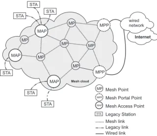
Figure 1. Elements of a 802.11s Network.
In a IEEE 802.11s Mesh Network there are tree types of nodes: Mesh Points (MPs), Mesh Access Points (MAPs), and Mesh Portal Points (MPPs). A MP is an IEEE 802.11s device that participates in the mesh routing process and can forward frames on behalf of other MPs in an ad-hoc way. In the IEEE 802.11s draft standard some Mesh Points that have additional Access Point functional-ity are called Mesh Access Points (MAPs). A MAP allows to support other wireless Legacy Stations (STA), e.g. IEEE 802.11b/g/n devices, acting as bridge between the STA and the mesh network. Some other special MPs can act as Portal between the mesh network and other IEEE 802 networks, usually wired Ethernet networks. These nodes
are called Mesh Portal Points and allow the extension of the mesh network coverage. Figure 1 illustrate the rela-tionship between the different types of nodes in a mesh network. An interesting survey on WMNs can be found in [1].
IEEE 802.11s Mesh Networks use a multi-hop wire-less relaying infrastructure, where all nodes cooperatively maintain network connectivity. Data can be routed from the source node to the destination node using multi-hop communication. In a IEEE 802.11s Mesh Network, rout-ing is performed at the data link layer and is given the name of path selection. Prior to draft version 1.06, every MP supported two routing protocols: the Hybrid Wire-less Mesh Protocol (HWMP) [4] as the default routing protocol and the Radio-Aware Optimized Link State Rout-ing Protocol (RA-OLSR) [10] as an optional one. Since draft version 1.07, the RA-OLSR was removed from the IEEE 802.11s specification. HWMP can work in both re-active and prore-active modes. In rere-active routing the route discovery is performed on-demand. In proactive routing, performed only by MPPs, a distance vector tree is used to avoid unnecessary routing path discovery and recovery messages. The RA-OLSR protocol is a proactive, link-state wireless mesh path selection protocol based on the Optimized Link State Routing (OLSR) protocol [6]. It also include extensions like the Fisheye State Routing (FSR) protocol [9], and the use of radio-aware metrics. However, both HWMP and RA-OLSR have several shortcomings, namely in what concerns the scalability of the network.
2.2 Distributed Hash Table (DHT)
A Distributed Hash Table (DHT) enables the applica-tion of the hash table concept to a distributed environment. It allows the efficient access to data through the associa-tion of a key to each data element. DHT networks have gained popularity as they are the underlying support for the organization of Peer-to-Peer (P2P) networks, such as Chord [15] and Pastry [14]. Basically the DHT uses a space of identifiers to guide the resource allocation pro-cess, where a resource can be a process to be executed or a information to be stored. The space of identifiers is divided among the nodes that form the DHT and the re-sources are mapped into that space, typically using a hash function. Each network node is responsible for all the re-sources mapped to its identifiers. Such identifiers are also referred as keys.
Obviously, the nodes participating in the DHT use a physical communication network, such as the Internet, to exchange messages. However, they also create a new net-work, superimposed upon this physical netnet-work, called the overlay network. This overlay network has its own topology and routing protocols that are specified by the DHT. Moreover, DHTs are typically multi-hop networks, where each node forwards the messages to the nodes that are nearest to their destination addresses.
2.3 Wireless Industrial Networks
The industry has traditionally relied on wired networks to transmit data among control applications, controllers, sensors and/or actuators, and other components. Most of this communication is supported by fieldbus systems [18] like Foundation Fieldbus, PROFIBUS, WorldFIP, CAN or ControlNet. However, the need for greater flexibility and lower costs has led to consider the application of wireless network technologies in industrial environments.
It is well known that wireless communication in indus-try will deliver cost advantages and increase the flexibility in plants. The cost and time needed for installation and maintenance of a large number of data cables in the indus-trial floor is significant. Wireless connections can greatly reduce these costs and time. Moreover, for some indus-tries and factories, the use of wireless technologies allow a rapid and easy plant setup and reconfiguration. It also al-lows the reduction of cable breakage in industrial/factory floor when dealing with movable components.
Despite the obvious benefits of wireless technologies for industrial settings, there are still some important con-straints to be solved. One of the most important issues is the unpredictable behavior and the higher error rate in wireless channels. This restriction is caused by limita-tions of the MAC layer on most of the current wireless technologies and becomes more relevant in industries with metallic clutter and obstacles. We believe that is possible to mitigate these limitations by extending the wireless net-work coverage. However, again the scalability issue still need to be solved by additional measures, in order to allow such coverage extension.
3. Overview
The DHT-based Cluster Routing Protocol (DCRP) in-tegrates clustering with DHTs to enhance the scalability of routing in 802.11s networks. Clustering allows for the use of hierarchical routing and therefore to reduce the amount of routing traffic. The routing information that is not ex-changed through the routing protocols is kept in DHTs, which support a rather efficient access.
Inter MP (iMP) Border MP (bMP) Cluster
Mesh link between bMPs
STA
STA STA STA Legacy station
Mesh link Legacy link Proxy-MAP
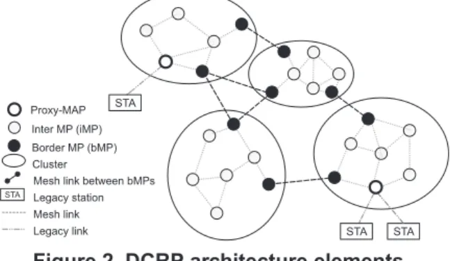
Figure 2. DCRP architecture elements.
As shown in Figure 2, MPs physically close are grouped in clusters. Most MPs in a cluster communicate only with MPs in the same cluster, whereas a few MPs in
a cluster communicate both with MPs in the same cluster and MPs in other clusters. We call the latter border MPs (bMP) and the former internal MPs (iMP). All MPs in a cluster maintain an intra-cluster routing table by executing an intra-cluster routing protocol. In addition, the bMPs of each cluster maintain an inter-cluster routing table by ex-ecuting a mesh-wide inter-cluster routing protocol.
In order to reduce the traffic generated by the intra-cluster routing protocol, this protocol exchanges routing information only for MPs. Routing information relative to stations in the cluster, i.e. the proxy-MAP a station is associated with, is kept in a DHT. For each cluster, there is an intra-cluster DHT (intra-DHT), whose nodes are the MPs of that cluster. Each MP is identified in the DHT by a random unsigned integer, id, which is the result of apply-ing a hash function to its MAC address. Thus, to learn the id of a node, it is enough to know its MAC address. The DHT entry with routing information for a given station is stored in the MP whose id is closest to the id of that sta-tion. We call this MP the intra-cluster key MP (intra-kMP) of that station.
Likewise, the inter-cluster routing protocol exchanges routing information regarding only bMPs. Routing infor-mation relative to other nodes, i.e. stations and iMPs, is kept in a mesh-wide DHT, the inter-cluster DHT (inter-DHT). As the inter-routing protocol is aware only of bMPs, each entry in this DHT must contain the MAC ad-dress of a bMP of the cluster to which the corresponding node belongs. We call this bMP the proxy-bMP for the node. The DHT entry for a given node is stored in the bMP whose id is closest to this node id. This bMP is known as the inter-cluster key MP (inter-kMP) of that node.
As there is a one-to-one map between a routing pro-tocol instance and a DHT, each node of a DHT knows the remaining nodes of that DHT, and therefore the DHT overlay network is a fully connected graph, i.e. the set of neighbors of a given node comprises all other DHT nodes. In order to allow routing of frames in the DHT, each DHT node maintains a DHT neighbor table (NT), which just maps the ids of the DHT nodes to their MAC addresses. As the id of a node can be determined from its MAC ad-dress, the maintenance of NT is for free: it is provided by the corresponding instance of the routing protocol. Inser-tion of the entries in the DHT is also rather efficient and straightforward: when a station associates with a MAP, the latter inserts an entry for that station both in the intra-cluster DHT, for the local intra-cluster, i.e. in its intra-kMP, and in the inter-cluster DHT, i.e. in its inter-kMP. Note that most likely the two entries are different and are inserted in different nodes.
In addition to the already mentioned tables, an MP also keeps a proxy cache (P-cache), which maps the MAC ad-dress of a station to the MAC adad-dress of a proxy-MP of that station: the proxy-MAP for MPs in the same cluster and the proxy-bMP for MPs in other clusters. The purpose of this cache is to avoid DHT-routing, which is very likely less efficient than physical routing.
Therefore, DCRP always tries to forward frames using physical routing information. Only if no information is available, does it resort to DHT-based routing, i.e. it for-wards the frames to a kMP.
To populate the proxy cache, when a kMP receives a frame routed through the DHT and it has an entry for the frame’s final destination in its DHT, it sends back a redi-rect message to the node at the other end of the DHT-hop, which in turn may forward it back to the other end of the previous DHT-hop, if any. This redirect message contains the address of the destination of the frame forwarded by the kMP and the MAC address of the proxy MP (either the proxy-MAP or the proxy-bMP) of the destination.
4. DCPR Protocol
In this section we provide a detailed description of DCRP. First, we outline the clustering technique applied to create the clusters. Then, we describe the routing infor-mation used by DCRP and how this routing inforinfor-mation is maintained. We start with the routing tables used to route frames in the physical network. After that, we present the different DHTs that are used for overlay routing. Next, we describe how this information is used by DCRP to for-ward frames. We finalize this section with a discussion of some relevant issues.
4.1. Clustering
In DCRP, we use a modified version of the Efficient Clustering Scheme (ECS) [19]. The clustering module is implemented as an OLSR plugin. To avoid sending sig-naling packets with medium contention, all cluster forma-tion/maintenance messages are piggybacked into HELLO advertisements of the routing protocol. When a node re-ceive a cluster message, it will analyze the membership cluster ID of the source node and attach this information in the OLSR neighbor database, where it can be later used for the forwarding process. Therefore, the clustering tech-nique helps to reduce the flooding during route discovery phase, since the broadcast of routing messages can be con-strained within the cluster.
4.2. Routing Tables
As described above, each MP in a cluster has two rout-ing tables (RT), an intra-cluster RT (intra-RT) and an inter-cluster RT (inter-RT). The intra-RT maps the MAC ad-dress of each MP in the cluster to the MAC adad-dress of the next node on the path to that MP. Likewise, the inter-RT maps the MAC address of each bMP to the MAC address of the next bMP on the path to the former bMP. Whereas looking up an MP in the intra-RT always returns a (phys-ical) neighbor MP, i.e. the two MPs are connected by a physical link, looking up a bMP in the inter-RT may not return a neighbor MP. In this case, an additional lookup in the intra-RT will be needed to find the next hop to the looked-up bMP.
In order to create and maintain a cluster’s intra-RT all MPs in that cluster execute an instance of the routing pro-tocol. Likewise, to create and maintain the inter-RT, all the bMPs in the mesh execute another instance of the routing protocol. DCRP can be used with any proactive proto-col, i.e. a protocol that maintains the routing tables entries even if they have never been used to forward a frame. In this paper, we assume that RA-OLSR is used both as the intra-cluster routing protocol in all clusters and as an inter-cluster routing protocol. RA-OLSR was chosen because it is a protocol specially developed for wireless mesh net-works that was specified as one of the two routing proto-cols in an earlier IEEE 802.11s draft.
The intra routing protocols are standard instances of the RA-OLSR, in which the MPs exchange bothHELLO andTCmessages. The latter are messages that are flooded in the network and that contain the state of a node links. TheHELLOmessages enable an MP to learn the network topology in its neighborhood, so that the number ofTC messages transmitted can be reduced, but still ensuring that everyTCmessage is received by all MPs in the cluster. The inter routing protocol deviates from the standard RA-OLSR protocol in that all bMPs of a cluster behave as if they were a single node. This means that a cluster bMP may generate a TC message with the state of a link that is not its own, but of another bMP of its cluster. Fur-thermore, because the bMP in the other end of these links are not physical neighbors of the node generating the TC message, different links may have different propagation delays. Thus, to take this into account, the inter-cluster instance of the RA-OLSR protocol uses not only the qual-ity metric specified in RA-OLSR, but also a new metric called propagation delay.
Although iMPs do not execute the inter-cluster routing protocol, they keep a snapshot of the inter-cluster routing table that is periodically refreshed by the bMPs in their cluster, if needed. This snapshot is used solely to improve the performance of forwarding inter-cluster traffic, not to ensure its correctness. If the information in the snapshot is stale, the iMPs may forward a frame to a bMP in the cluster that is not the one in the shortest path, but that bMP will forward the frame in the right direction. Therefore, the refresh period of the snapshots can be tuned to keep the associated traffic within acceptable bounds. Furthermore, this period may be set independently in each cluster.
4.3. DHT
Each MP in a cluster is a node of the intra-cluster DHT (intra-DHT) for that cluster and keeps the entries of the DHT for the cluster nodes of which it is the kMP, more specifically the intra-kMP. The entries of the intra-DHT map the id of a node to the MAC address of its proxy MAP. Each bMP is also a node of a mesh-wide DHT (inter-DHT) and keeps the entries of this DHT for the nodes, either MPs or stations, of which it is the kMP, more specifically the inter-kMP. The entries of the inter-DHT map the id of a node to the MAC address of its
proxy-bMP, i.e. a bMP in that node’s cluster. We call the set of entries of the intra-DHT/inter-DHT kept by an MP (i.e. the entries for which the MP is a kMP), that MP’s intra-DHT/inter-DHT.
Populating the DHTs with entries is very simple. When an MP joins the mesh, it adds itself in its inter-kMP, by sending to that inter-kMP an add-entry message. When a station associates with a MAP, the latter adds the entries for the station to both the intra-DHT and the inter-DHT, by sending an add-entry message to each of the intra-kMP and the inter-kMP of that station respectively.
In order to support the forwarding of messages in DHT overlay networks, an MP maintains a DHT neighbor table (NT) for each DHT it is a member of. Each entry in a NT maps a DHT node id to its MAC address.
A key feature of DCRP is that there is a one-to-one map between an instance of the routing protocol and a DHT: all MPs in a cluster execute the intra-cluster RA-OLSR and are also members of that cluster intra-DHT; all bMPs in the mesh execute the inter-cluster RA-OLSR and are also members of the inter-DHT. Because, in RA-OLSR each node generates TC messages that are flooded in the corre-sponding network, it is clear that, by sharing information between RA-OLSR and the DHT, each node in a DHT knows all other nodes in that DHT. I.e. each node of the DHT is a (virtual) neighbor of all other DHT nodes. This means that routing in an DCRP overlay network is very efficient: all DHT nodes are just one hop away of each other. Furthermore, this is achieved using only the mes-sages already exchanged by RA-OLSR, i.e. no additional message is generated to create or to maintain routing in-formation for the DHT overlay.
7 225 33:33:33:33:33:33 121 95 58 11:11:11:11:11:11 202 240 72 44:44:44:44:44:44 192 22 123 55:55:55:55:55:55 237 156 254 22:22:22:22:22:22 37
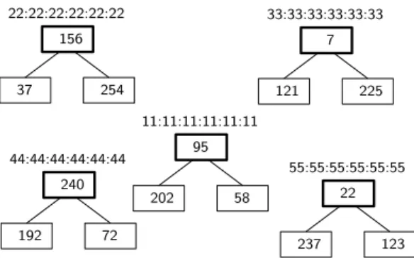
Figure 3. Cluster example, with MAP MAC addresses and ids for all nodes.
We illustrate the use of DHTs in DCRP by means of the intra-DHT (Figure 4) for the cluster shown in Figure 3. This cluster has 5 MPs, represented as boxes with a thicker border, whose MAC addresses are: 11:11:11:11:11:11, 22:22:22:22:22:22, 33:33:33:33:33:33, 44:44:44:44:44:44 and
55:55:55:55:55:55. Through the flooding of TC messages
made by the RA-OLSR protocol instance executed by the MPs, each of these MPs will learn about the other MPs. DCRP then applies an hash function to the MAC address of each MP to determine its id, which is shown inside the
MP’s box in Figure 3, and adds to the intra-DHT neighbor table an entry that maps the id of each MP in the cluster to its MAC address. Figure 4 (i) shows the DHT neighbor table for each MP in the cluster.
id MP MAC address 7 33:33:33:33:33:33 22 55:55:55:55:55:55 95 11:11:11:11:11:11 156 22:22:22:22:22:22 240 44:44:44:44:44:44
id proxy-MAP MAC address 37 22:22:22:22:22:22 58 11:11:11:11:11:11 72 44:44:44:44:44:44
(i) (ii)
Figure 4. (i) DHT neighbor table. (ii) DHT en-tries stored in MP with id-95.
The cluster MPs store entries of the cluster’s intra-DHT that map a station id (represented as a box with a thinner border) in Figure 3 to the MAC address of its proxy-MAP. Each DHT node stores the entries whose ids fall between, but not including, the id of the node that precedes it in the id circle, and its own id. E.g., the MP whose MAC address is11:11:11:11:11:11 will store the entries whose ids are larger than 22, i.e. the id of the MP that precedes it in the id circle, and smaller or equal to 95, i.e. its own id, as shown in Figure 4 (ii). In this example, we assume that the hash values are 8 bit unsigned integers, i.e. values in the range from 0 to 255. In a real implementation, a 128 bit or larger hash function, would be used, thus the probability of id collisions is close to 0.
4.4. Forwarding
Forwarding is the process executed in each MP when receiving a frame whose final destination is not the MP. In the context of IEEE 802.11s networks, it comprises the modification of the appropriate address fields and the re-transmission of the frame to the next hop in the path to the final destination. To determine the values of the ad-dress fields, the MP may lookup any of the routing tables it maintains.
All transmitted frames contain 6 address fields. In Addr5 and Addr6 fields it contains the MAC addresses of the final destination station and of the original sender station. Thus, these fields are set at the proxy-MAP of the original sender station, and are not modified until they reach the proxy-MAP of the final destination. Ad-dress fields Addr1 and Addr2 always contain the MAC ad-dresses of the nodes at the end of the physical link, i.e. of the physical hop, and therefore are modified at every MP in the path. Address fields Addr3 and Addr4 contain the MAC addresses of the destination and source ends respec-tively of a path that may be comprised by several physical hops. These addresses are modified only at some MPs in the end-to-end path. To make it clear, when these ad-dresses are modified we use the expression relays to XXX and transmits to YYY with very precise meanings. The for-mer means that the Addr3 field of the frame is set to the MAC address of node XXX and Addr4 field of the frame
is set to the MAC address of the node that is relaying the frame. The expression transmits to YYY means that the Addr1 field of the frame is set to the MAC address of node YYY and Addr2 field of the frame is set to the MAC ad-dress of the node that is transmitting the frame.
We now detail how how routing information is used to forward frames. To focus just on the forwarding process, we assume that the proxy-cache does not have any entry for the looked up nodes, and therefore we omit all lookups in the proxy-caches.
Intra-cluster forwarding Figure 5 illustrates intra-cluster forwarding in the case where the proxy-MAP of the destination station is different from the one of the sender station. Solid arrows are paths followed by the frame in its end-to-end path from station STA1to station
STA2. The meaning of the dashed arrows is provided
be-low. The numbers associated with each of these paths are meant to help following the description of the forwarding process.
When the proxy-MAP of the sender MAP1 receives a frame (step 1) whose destination is a station that is not associated with it, it looks up in the intra-RT for the desti-nation address. As the intra-RT contains only information on MPs within the cluster and the destination node is out-side the cluster, the lookup returns no entry. Therefore, the sender’s proxy-MAP applies DHT-routing. I.e., it re-lays the frame to the intra-kMP of the destination station (step 2). MAP2 MAP1 STA1 STA2 intra-KMP redirect 1 3 2 3 4 5
Figure 5. Intra-cluster forwarding.
As the overlay network is a complete graph, the proxy-MAP of the sender station knows the intra-kMP. To find the next hop in the physical network, the sender’s proxy-MAP only has to lookup in the intra-RT the entry for the intra-kMP.
In the general case, the frame will have to traverse sev-eral MPs (not represented in Figure 5) before arriving to the intra-kMP. The forwarding process in each of these MPs is standard forwarding with proactive routing: the MP looks up in its intra-RT the next hop in the path to the intra-kMP, whose address is in the Addr3 field of the frame, and transmits the frame to the returned MP.
When the intra-kMP for the destination station receives the frame, it relays the frame to the proxy-MAP of the destination station and it sends a redirect message with the MAC addresses of the destination station and of its proxy-MAP back to the proxy-MAP of the sender station, whose address is in the Addr4 field of the relayed frame (step 3). In order to determine the MAC address of the
proxy-MAP of the destination station, the intra-kMP looks up in its (entries of the) intra-DHT for the entry of the final destination. To determine the next hop in the physical network for the frame and the redirect message, the intra-kMP looks up in the intra-RT for the entries associated with the proxy-MAPs of the destination station and of the sender station, respectively.
Both frames sent by the intra-kMP are forwarded in direction to their destinations using standard forwarding with proactive routing, already described above (the thin-ner dashed arrow represents the path followed by the redi-rect message). Likewise, forwarding with DCRP is simi-lar to the standard forwarding process by 802.11s proxy-MAP (step 4). MAP1 STA1 redirect egress-bMP intra-KMP inter-kMP redirect MAP2 STA2 proxy-bMP intra-KMP redirect 3 4 5 6 1 2 8 9 4 7 9 9
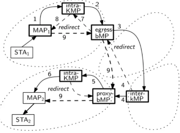
Figure 6. Inter-cluster forwarding.
The redirect message addressed to the proxy-MAP of the sender allows it to create an entry for the destination station in its proxy-cache. Thus, as long as that entry is kept in the proxy-cache, communication to the destination station will be done directly between the proxy-MAPs, as indicated by the thicker dashed arrow in Figure 5, not through the destination’s intra-kMP. I.e. no DHT-routing will be used (step 5).
Inter-cluster forwarding Figure 6 illustrates the case where the original sender and final destination stations are in different clusters. Furthermore, to illustrate a most general case, these two clusters are not neighbors of each other and therefore the frame has to traverse multiple clus-ters. Similarly to Figure 5, solid arrows represent the paths followed by the frame in its end-to-end path from station STA1to stationSTA2, thinner dashed arrows represent the
paths followed by redirect messages and, thicker dashed arrows represent the paths in the end-to-end path from proxy-MAPMAP1to proxy-MAPMAP2, after populating
the proxy-caches. As before, the numbers associated with these paths are meant to help following that description.
Processing of the frame by the sender’s proxy-MAP is as described in the previous paragraph. Indeed, the sender’s proxy-MAP does not know whether the destina-tion stadestina-tion is in the same cluster, and so it resorts to DHT-routing, relaying the frame to the intra-kMP of the desti-nation station (step 1). This may entail the forwarding of
nextHop = intraRT.lookup(frame.Addr3) if( nextHop == null ) {
nextBMP = interRT.lookup(frame.Addr3) if( nextBMP.isNeighbor() ) nextHop = nextBMP else nextHop = intraRT.lookup(nextBMP) }
Figure 7. DCRP’s algorithm to find next hop in physical network.
the frame by several MPs in the sender’s cluster.
The intra-kMP looks up in its intra-DHT for the entry of the destination station, as in the case of intra-cluster routing. However, as the destination station is in another cluster, no entry is found. Therefore, it too applies DHT-routing. But, rather than relaying the frame directly to the inter-kMP for the destination station, it relays it to one of the bMPs of its cluster (step 2). The reason for this is to avoid DHT-routing of the redirect frame that the inter-kMP will eventually send back. Although, the intra-kMP can choose any local bMP, the best choice is the local bMP closest to the inter-kMP. To find this bMP, which we call the egress-bMP, the intra-kMP may lookup its inter-RT (or a snapshot thereof). Because the intra-kMP and the egress-bMP are in the same cluster, forwarding of the frame until the selected bMP is as described in the para-graph on intra-cluster forwarding.
When the egress-bMP receives a frame from the lo-cal intra-kMP, it applies inter-cluster DHT-routing to that frame. First, it looks up in the inter-DHT routing table to find the inter-kMP of the destination station, and then it relays the frame to that inter-kMP (step 3). Although, the inter-kMP is only one-hop away in the overlay network, most likely it will be several hops away in the physical network, possibly in a different cluster, as shown in Fig-ure 6.
To find the next hop in the physical network, the egress bMP uses DCRP’s algorithm to determine the next hop in the physical network (Figure 7). This algorithm is also used by all the MPs (not shown in Figure 6) in the path from the egress-bMP to the inter-kMP of the destination station. In this particular case, the Addr3 field of the frame is the MAC address of the inter-kMP. The MP first looks up the inter-kMP in its intra-RT. If an entry is found in that RT, the MP will transmit the frame to the returned MP. If not, then the MP will lookup the inter-kMP in its inter-RT. As the inter-kMP is a bMP, the MP will find an entry. If the returned bMP is a (physical) neighbor, then the MP will transmit the frame to it. Otherwise, the bMP must be a bMP in the same cluster, and therefore the MP looks-up that bMP in its intra-RT, and transmits the frame to the returned MP. Note that if the MP is an iMP rather than a bMP, its inter-RT is a snapshot of the inter-RT and thus may not be up-to-date, i.e. its lookup may return a local bMP that is not in the shortest path to the inter-kMP.
However, once the frame reaches that (or another) bMP, the latter will use an up-to-date inter-RT and thus set the frame in the right path.
Eventually, the frame arrives at the inter-kMP of the destination station, which relays the frame to the proxy-bMP of the destination station and sends back a redirect frame to the egress-bMP at the source’s cluster (step 4). To determine the proxy-bMP of the destination station, the inter-kMP just looks it up in its inter-DHT table. So that the proxy-bMP of the destination station learns the egress-bMP of the sender’s cluster, and thus can forward a possible reply from station STA2to STA1without resort-ing to DHT-routresort-ing (the inter-kMP does not modify the Addr4 field). After modifying the Addr3 field, the inter-kMP uses the algorithm described in Figure 7 to deter-mine the next hop in the physical path to the proxy-bMP of the destination station, and transmits the frame to the returned MP. In the case illustrated in Figure 6, the inter-kMP does not belong to the destination cluster. Therefore, the lookup in the intra-RT will return no entry. The inter-kMP then looks up the inter-RT to find the next bMP in the path to the proxy-bMP. As this bMP is a neighbor, the inter-kMP just transmits the frame to that bMP. With re-spect to the redirect frame, the inter-kMP needs only to read the Addr4 field of the relayed frame to obtain the MAC address of the egress-bMP at the source’s cluster. Then it applies the DCRP algorithm (Figure 7) to deter-mine the next hop in the physical path to that bMP.
Forwarding at the destination cluster is similar to a intra-cluster forwarding. The main difference is that the proxy-bMP of the destination station already receives a 6 address frame, whereas the proxy-MAP of the source station in the intra-cluster case receives just a 4 address frame. However, both proxies just relay the frame to the cluster’s intra-kMP of the destination station (step 5), which then relays the frame to the proxy-MAP of the des-tination station and sends back a redirect frame to the proxy MP (the proxy-MAP in the case of intra-cluster warding, the proxy-bMP in the case of inter-cluster for-warding) (step 6).
To complete the description of the forwarding process in the inter-cluster case, we need to explain how the redi-rect frame sent by the inter-kMP to the egress-bMP of the sender’s cluster is processed. When the egress-bMP re-ceives a redirect frame addressed to itself, it creates an entry in its proxy-cache, and it sends the redirect frame to the intra-kMP of the sender’s cluster (step 7). Likewise, the intra-kMP of the sender’s cluster creates an entry in its proxy-cache, and sends the frame to the proxy-MAP of the sender’s station (step 8), which creates an entry in its proxy cache. This way, while this entry is in the proxy cache, forwarding of a frame to station STA2 can be done without recourse to DHT routing, i.e. using only the proxy-caches and the intra and inter routing tables. In this case, the path followed by a frame between the sender’s proxy-MAP and the destination’s proxy-MAP would be as shown by the thicker dashed arrows in Figure 6 (step
9).
4.5. Discussion about timeliness requirements
Industrial applications often impose upper-bounds on the propagation delay of frames. Meeting these require-ments for wireless mesh networks is particularly challeng-ing, especially when the network diameter increases. In-deed, each hop in a path leads to queueing delays that add up to the total propagation delay. One way to address this problem is to use a hybrid wireless-wired network. I.e., by interconnecting some bMPs with a wired network. By adopting such a deployment, it is possible to replace a wireless path, composed of several hops, by a single cable segment, and thus it is possible to reduce the propagation delay in order to meet the requirements of RT applica-tions.
The effectiveness of this approach depends on careful network planning to identify the devices that have RT-requirements and their physical location. This allows for the placement of bMPs to interconnect the associated clus-ters through a wired network. Note that not all clusclus-ters containing nodes with RT-requirements need to be directly connected to a wired network via a bMP. These clusters may be connected to the wired network through other clusters, as long as the propagation delay upper bounds are satisfied.
Wired segments pose no difficulty to the inter-cluster routing protocol. The used propagation delay metric al-ready considers that some links may comprise several hops. Therefore, it can be used also to distinguish between wireless and wired links. This information is included in the TC messages of the inter-cluster RA-OLSR protocol instance. By taking this information into account when building their routing trees, the bMPs can select paths that satisfy the RT requirements of the supported applications. Note that these hybrid networks still afford most of the advantages of WMN, because the clusters are WMNs, and thus most of the nodes are wireless. Thus, the intercon-nection of the cluster by wired segments is likely simpler and cheaper than the wiring of the clusters.
In DCRP, stations do not execute RA-OLSR, only MPs do. Thus, if these nodes are part of an infrastructure and are rather stable, i.e. remain operational for a long time, so will the DHT membership, i.e. the set of nodes that belong to the DHT. This means, that the DHT traffic induced by changes in the kMP of a station will be rather low.
5. Related Work
Motivated by the obvious benefits of the wireless com-munication, extensive research work have been done in order to apply available wireless technologies to the in-dustrial environments. Some works explore the use of IEEE802.11e networks [12], with some QoS enhance-ments in order to ensure real-time timeliness require-ments. Although this improvement addresses the relia-bility of the communication, the scalarelia-bility problem is
usually neglected. Furthermore, traditional protocols de-signed for 802.11 (WiFi) networks are insufficient to sup-port mesh networking, due to its poor scalability at the MAC layer, affecting the overall network performance. Several other research works are focused on Wireless Sen-sor Networks (WSNs), which are largely used for provide real-time data acquisition and control [11]. WSNs are usually not used in the control loop and so the real-time requirements are not hard [17]. WSNs based on IEEE 802.15.4 and ZigBee have been largely used for moni-toring in industrial settings. Recently the Instrumenta-tion, System, and Automation Society (ISA) release the ISA SP100 that aims to be a common standard for some industrial applications. However, all these technologies designed for WSNs have limited data rates, which do not cover the overall range of applications that can be found in the industrial environments. More details about these WSN technologies can be found in [17].
The DCRP relies on the use of proxies, DHTs and clus-tering. Although these concepts are widely used in many different scenarios including mesh networks, in this work we propose to use them in a integrated way, exploring their synergies, in order to obtain a more scalable routing protocol for IEEE 802.11s WMNs.
The proxy concept is used both in HWMP [4] and in RA-OLSR [10] protocols to reduce the amount of in-formation required to route frames to non-mesh stations. In both protocols the discovery of a station’s proxy re-lies on broadcast messages. HWMP uses broadcast mes-sages for route discovery, whereas RA-OLSR uses it for route announcement. Our protocol does not require broad-cast messages for proxy discovery, instead it uses DHT to maintain this information. Furthermore, the DCRP pro-tocol extends the proxy concept to clusters, by means of bMP proxies.
Other works that use DHTs in the wireless routing pro-cess leave the task of determining the route to the DHT. In [5,7,21] no additional routing protocol is needed, whereas in [3, 16, 20] the DHT is used to indicate the next node to which the frame must be send. As this next node may not be reachable within 1-hop, in the latter case, an addi-tional path selection protocol is required, e.g. HWMP, for discovery the route to this node. In contrast with DCRP, which was designed to be easily integrated with the IEEE 802.11s standard, those protocols require the modification of the IEEE 802.11s frame, and force the use of a specific routing protocol. As illustrated above, the DCRP uses the IEEE 802.11s frame format. Furthermore, although in the DCRP description RA-OLSR was used for both intra and inter-cluster routing, it is clear that DCRP can be used with other proactive routing protocols.
Clustering is widely regarded as an effective approach to increase the scalability of WMNs. Several works, e.g. [8, 13] and [2] have proposed modified OLSR versions with clustering. Among others, a key difference between these proposals concerns inter-cluster frame forwarding. In [8], the authors propose the use of special nodes with
multiple radios, called cluster heads, that are assumed to be able to communicate directly with neighbor clus-ter heads using one of their radios. In contrast, in [13] and [2], as well as in DCRP, nodes need only one radio and the transmission among neighbor clusters is done trough border nodes. However, whereas in those proposals the exchanged messages among clusters include also informa-tion about internal nodes, in DCRP the inter-cluster proto-col exchanges information about border MPs only. This is possible, due to the concept of proxy bMP and the use of DHTs. As a result, the DCRP generates much less inter-cluster routing traffic than other proposals.
Finally, when HWMP operates in proactive mode, all frames must pass through the root node, which is usually an MPP node. Thus, the network performance degrades as the intra-mesh traffic grows. This is a severe constraint to the network scalability.
6. Preliminary Evaluation Results
In order to provide a rough assessment of the DCRP performance, an initial set of simulations was done based on the comparison between the number of Topology Con-trol (TC) messages generated by DCRP vs. OLSR. The purpose of such simulations is to provide preliminary es-timates of the overhead caused by broadcast messages in DCRP, when compared to OLSR. All simulations were carried out using the Network Simulator 3 (ns-3).
The topology of the used network is a square grid of NxN nodes (MPs). The distance between neighbor nodes in the horizontal and vertical directions is 100m and con-stant for the entire grid. Furthermore, the radio ranges of all nodes are set so that a node can communicate in one hop only with its neighbors in the horizontal and vertical directions. As mentioned above, there are no stations. In our experiments we considered different values for N (5 to 30, in steps of 5) and run the model for 5 minutes, 5 times, for each value of N.
For the analysis of DCRP, we partition the grid in clus-ters of 25 nodes in a square grid of 5x5 nodes, with 4 bMPs. The size of the cluster was chosen taking into account that the 802.11s draft standard was designed for meshes up to 32 MPs. Under these assumptions, the rout-ing traffic in number of messages generated by the DCRP protocol can be estimated by:
NDC RP = C× Mc+ Ic× H (1)
where C is the number of clusters, Mc is the number
of TC messages sent by the OLSR protocol in a 5x5 clus-ter, Icis the number of TC messages generated by a grid
with as many nodes as bMPs in the mesh, and H is the average number of hops between bMPs within a cluster, i.e. the propagation delay metric. Thus the first term in (1) is the total routing traffic generated by all instances of the intra-cluster routing protocol, whereas the second term is an estimation of the total routing traffic generated by the inter-cluster routing protocol. The factor H is used
to take into account that communication between bMPs in the same cluster may require more than one hop.
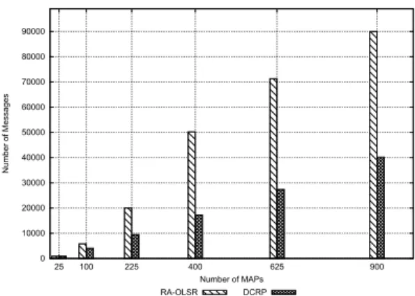
0 10000 20000 30000 40000 50000 60000 70000 80000 90000 25 100 225 400 625 900 Number of Messages Number of MAPs RA-OLSR DCRP
Figure 8. Comparison of the number of mes-sages generated by the routing protocol.
Figure 8 shows the results obtained with the ns-3 sim-ulation model for the OLSR protocol and those obtained for DCRP using expression (1). In computing the value of expression (1) we used for Mcand Icvalues obtained
also with the ns-3 simulation model. As for H we used the value of 5, as in our simulation we have used a 5x5 grid.
As we would expect, DCRP generates a lower number of TC messages than OLSR. The results are promising, but the used models are still rather approximate. Further-more, as we stated, these experiments consider only the clustering aspect of the DCRP. The benefits of the DHT-based service have yet to be evaluated.
Presently, we are setting up a full ns-3 model in order to make the performance assessment of the DCRP. Such model encompasses a RA-OLSR version on ns-3 and a complete simulation model of DCRP. The performance metrics that will be analyzed include: network throughput and access delay. The first preliminary results are quite encouraging, but at the moment of writing of this paper, we still do not have a full set of results.
7. Conclusion
In this work we have proposed a path selection proto-col that increases the scalability of 802.11s WMNs. We partition the network in clusters and use proxies to reduce the amount of routing information exchanged in the mesh. To make up for the information that is not exchanged by the routing protocols, we rely on a DHT that maps stations to their proxies. The combination of these features allows each cluster to run its own routing protocol instance. This intra-cluster routing protocol is executed only by the MPs of the cluster. In order to support inter-cluster commu-nication, the border MPs of all clusters execute another routing protocol instance, the inter-cluster routing proto-col.
The key impact of this work is that it can meaningfully reduce the number of routing protocol messages broad-casted. The main reason for this is that changes to a route in a cluster usually do not lead to routing messages broad-casted by nodes that do not belong to that cluster. Further-more, the size of the routing messages that traverse multi-ple clusters are much reduced, because they only contain information about the border MPs.
The obtained results from a preliminary evaluation in-dicate that the DCRP protocol may be an adequate solu-tion to deal with scalability issues in WMNs.
References
[1] I. F. Akyildiz, X. Wang, and W. Wang. Wireless mesh networks: A survey. Computer Networks, 47(4):445–487, 2005.
[2] E. Baccelli. OLSR Scaling with Hierarchical Routing
and Dynamic Tree Clustering. In IASTED International Conference on Networks and Communication Systems (NCS),(Chiang Mai, Thailand), 2006.
[3] E. Baccelli and J. Schiller. Towards scalable manets. ITS Telecommunications, 2008. ITST 2008. 8th International Conference on, pages 133–138, Oct. 2008.
[4] M. Bahr. Update on the hybrid wireless mesh protocol of ieee 802.11s. 2007 IEEE Internatonal Conference on Mo-bile Adhoc and Sensor Systems, MASS, pages 1–6, 2007. [5] M. Caesar, M. Castro, E. B. Nightingale, G. O Shea,
and A. Rowstron. Virtual ring routing: Network
rout-ing inspired by dhts. Computer Communication Review, 36(4):351–362, 2006.
[6] T. Clausen and P. Jacquet. IETF RFC-3626: Optimized Link State Routing Protocol OLSR. The Internet Society http://www. ietf. org/rfc/rfc3626. txt, 2003.
[7] T. Fuhrmann, P. Di, K. Kutzner, and C. Cramer. Push-ing Chord Into the Underlay Scalable RoutPush-ing for Hybrid MANETs. Univ., Fak. f¨ur Informatik, Bibl., 2006. [8] Y. Ge, L. Lamont, and L. Villasenor. Hierarchical
OLSR-a scOLSR-alOLSR-able proOLSR-active routing protocol for heterogeneous OLSR-ad hoc networks. In IEEE International Conference on Wire-less And Mobile Computing, Networking And Communi-cations, 2005.(WiMob 2005), volume 3, 2005.
[9] M. Gerla, X. Hong, and G. Pei. Fisheye state routing pro-tocol (FSR) for ad hoc networks. IETF Draft, 2002. [10] G. Hiertz, S. Max, R. Zhao, D. Denteneer, and L.
Berle-mann. Principles of IEEE 802.11 s. In Computer Commu-nications and Networks, 2007. ICCCN 2007. Proceedings of 16th International Conference on, pages 1002–1007, 2007.
[11] K. Low, W. Win, and M. Er. Wireless sensor networks for industrial environments. In Computational Intelligence for Modelling, Control and Automation, 2005 and Interna-tional Conference on Intelligent Agents, Web Technologies and Internet Commerce, International Conference on, vol-ume 2, 2005.
[12] R. Moraes, F. Vasques, P. Portugal, and J. Fonseca. VTP-CSMA: A Virtual Token Passing Approach for Real-Time Communication in IEEE 802.11 Wireless Networks. IEEE Transactions on Industrial Informatics, 3(3):215– 224, 2007.
[13] F. Ros and P. Ruiz. Cluster-based OLSR extensions to re-duce control overhead in mobile ad hoc networks. In Pro-ceedings of the 2007 international conference on Wireless communications and mobile computing, pages 202–207. ACM New York, NY, USA, 2007.
[14] A. Rowstron and P. Druschel. Pastry: Scalable,
dis-tributed object location and routing for large-scale peer-to-peer systems. In IFIP/ACM International Conference on Distributed Systems Platforms (Middleware), volume 11, pages 329–350. Heidelberg, 2001.
[15] I. Stoica, R. Morris, D. Liben-Nowell, D. R. Karger, M. F.
Kaashoek, F. Dabek, and H. Balakrishnan. Chord: A
scalable peer-to-peer lookup protocol for internet applica-tions. IEEE/ACM Transactions on Networking, 11(1):17– 32, 2003.
[16] K. Takeshita, M. Sasabe, and H. Nakano. Mobile p2p net-works for highly dynamic environments. Pervasive Com-puting and Communications, 2008. PerCom 2008. Sixth Annual IEEE International Conference on, pages 453– 457, March 2008.
[17] A. Willig. Recent and Emerging Topics in Wireless Indus-trial Communications: A Selection. IEEE Transactions on Industrial Informatics, 4(2):102–124, 2008.
[18] A. Willig, K. Matheus, and A. Wolisz. Wireless tech-nology in industrial networks. Proceedings of the IEEE, 93(6):1130–1151, 2005.
[19] J. Y. Yu and P. H. J. Chong. An efficient clustering scheme for large and dense mobile ad hoc networks (manets). Computer Communications, 30(1):5–16, 2006.
[20] T. Zahn and J. Schiller. MADPastry: A DHT Substrate for Practicably Sized MANETs. In Proc. of ASWN, 2005. [21] T. Zahn and J. Schiller. Dht-based unicast for mobile ad
hoc networks. Proceedings - Fourth Annual IEEE Interna-tional Conference on Pervasive Computing and Communi-cations Workshops, PerCom Workshops 2006, 2006:179– 183, 2006.