Repositório ISCTE-IUL
Deposited in Repositório ISCTE-IUL:
2018-10-12
Deposited version:
Post-print
Peer-review status of attached file:
Peer-reviewed
Citation for published item:
Cruz, C. C., Fernandes, C. A., Matos, S. A. & Costa, J. R. (2018). Synthesis of shaped-beam radiation patterns at millimeter-waves using transmit arrays. IEEE Transactions on Antennas and Propagation. 66 (8), 4017-4024
Further information on publisher's website:
10.1109/TAP.2018.2836383
Publisher's copyright statement:
This is the peer reviewed version of the following article: Cruz, C. C., Fernandes, C. A., Matos, S. A. & Costa, J. R. (2018). Synthesis of shaped-beam radiation patterns at millimeter-waves using transmit arrays. IEEE Transactions on Antennas and Propagation. 66 (8), 4017-4024, which has been
published in final form at https://dx.doi.org/10.1109/TAP.2018.2836383. This article may be used for non-commercial purposes in accordance with the Publisher's Terms and Conditions for self-archiving.
Use policy
Creative Commons CC BY 4.0
The full-text may be used and/or reproduced, and given to third parties in any format or medium, without prior permission or charge, for personal research or study, educational, or not-for-profit purposes provided that:
• a full bibliographic reference is made to the original source • a link is made to the metadata record in the Repository • the full-text is not changed in any way
The full-text must not be sold in any format or medium without the formal permission of the copyright holders. Serviços de Informação e Documentação, Instituto Universitário de Lisboa (ISCTE-IUL)
Av. das Forças Armadas, Edifício II, 1649-026 Lisboa Portugal Phone: +(351) 217 903 024 | e-mail: [email protected]
Abstract – Transmit-arrays have been mostly used for beam
collimation applications, either with fixed or scanning beam capability. But transmit-arrays can also be used to synthesize power radiation patterns complying with power pattern templates. A new analytical formulation is presented here to obtain a phase-only correction function corresponding to a given power template. The transmit-array transforms the known power radiation pattern of the primary source into a desired output power pattern. The proposed formulation, specialized for axial-symmetric structures, is based on Geometrical Optics and provides the solution directly from the evaluation of two closed-form first-order differential equations. As a proof of concept, a sec2 with a roll-off at 45º is defined as the target power pattern, at
the 30 GHz Ka-band. A 10.8 dBi radiation pattern with circular polarization is used to illuminate a 180 mm × 180 mm transmit-array with 60 mm focal distance. Previously designed 3.35 mm thick phase-delay unit-cells are used as an example to implement the calculated phase distribution over the transmit-array aperture. The measured antenna radiation pattern matches quite well the template, with a steep fall of the radiation at the roll-off angle and low cross-polarization. This validates the concept, the formulation and the fabricated prototype.
Index Terms— Transmit-arrays, planar lens antennas,
radiation pattern shaping, Geometrical Optics, secant squared power pattern, mm-wave antennas.
I. INTRODUCTION
NTENNA radiation pattern shaping is widely used in different applications. For instance, contoured beams may be required in satellite antennas to restrict Earth coverage to certain areas with shaped borders [1], leaving out the neighboring regions. Radars are another traditional application, where cosecant-squared beams may be used to ensure constant flux illumination of the target, independent of the distance [2]. A similar requirement has also been applied for some space-borne synthetic aperture radar antennas [3].
This work is partially supported by the Fundação para a Ciência e a Tecnologia under the grant UID/EEA/50008/2013. Catarina Cruz, Carlos A. Fernandes, Sérgio A. Matos, and Jorge R. Costa are with Instituto de Telecomunicações, Instituto Superior Técnico, Universidade de Lisboa, Av. Rovisco Pais 1, 1049-001 Lisboa, Portugal (phone 218418480 fax +351-218418472 e-mail [email protected]).
Sérgio A. Matos and Jorge R. Costa are also with Instituto Universitário de Lisboa (ISCTE-IUL), Departamento de Ciências e Tecnologias da Informação Av. das Forças Armadas, 1649-026 Lisboa, Portugal.
For the last two decades, the concept of constant flux illumination and of shaped beams in general, has been extended also to mobile communications [4] and to mm-wave LANs [5]. It is a simple first order approach to maintain the link budget in the coverage area, without the need to replace omnidirectional antennas on the mobile terminal with sophisticated beam forming antennas.
Three basic antenna technologies have been used to accomplish the desired beam shaping: arrays, reflectors and lenses. Conceptually, arrays are the most flexible structures to obtain any type of radiation pattern, offering its geometry and complex valued feeding of the individual elements as design degrees of freedom. The theory is well established [6], [7] but the drawback is that the beam-forming network may become complex, expensive and lossy, especially at mm-waves. Shaped reflectors are also well documented [8], [9]. They can use just one or multiple primary feeds. The drawback is that the feed is in front of the aperture or even offset and tends to limit the performance and flexibility of this solution. Once fabricated, the radiation pattern re-configurability is low or none. Dielectric lenses on the other side, and namely integrated lenses, appear as very attractive shaping beam solutions at mm-waves [10]-[11]. The integrated feed behind the lens enables complying with demanding output beam shaping templates. But dielectric lenses tend to be bulky and heavy [12]-[13], with non-negligible insertion losses and also suffer from the same re-configurability limitations as reflectors.
Reflect-arrays [14], [15] and transmit-arrays [16]-[22] are special cases of reflectors and lenses, respectively. Both are thin, planar, light-weight, low-cost structures, that can transform the phase and amplitude of the incident wave into some prescribed output form. Furthermore, unit cells are potentially reconfigurable [16], although this characteristic is not addressed in this paper. Transmit-arrays are a natural candidate to explore the possibility of beam shaping. With the feed behind the aperture as in lenses, transmit-arrays are extremely flexible to control the beam radiation direction while keeping with a low profile [17]. The challenge is that the operation principle
Synthesis of Shaped Beam Radiation Patterns at
mm-Waves Using Transmit-arrays
Catarina C. Cruz, Carlos A. Fernandes, Senior Member, IEEE, Sérgio A. Matos, Member IEEE and Jorge R. Costa, Senior Member, IEEE
is normally based solely on the local phase shifts introduced by the unit cells when the incident wave passes through [18]. The transmission coefficient amplitude at each cell must be desirably close to one to maximize the total efficiency of the transmit-array, so no amplitude control can be expected from this side.
In most applications, the output wave front is planar [19] and eventually tilted [17], [20], [21]. In order to shape the output beam to meet an amplitude template while taking into account the primary feed radiation pattern, the appropriate shape of the wave-front must be found. To the authors’ best knowledge, reports on amplitude shaping produced by transmit-arrays are very scarce in the literature [23], [24]. In these references, the transmit-array is designed as a phase and amplitude shifting surface (PASS) to produce an axial-symmetric flat-top radiation pattern with roll-off at 20º with linear polarization. The design follows a technique presented in [25] based on the classical array theory, applied to a circular grid planar array. The authors iterate the phase and amplitude of the array elements in each ring until the template is matched within some error criterion. The optimized amplitude and phase distribution is then mapped to the transmit-array unit cells. The demonstration example in [23] is a 152.4 mm diameter transmit-array with 132 mm focal distance, linear polarization PASS unit cells, for 30 GHz. Shaping of the wave amplitude using unit-cells actually means introducing insertion loss. In [23] these losses are higher than 4 dB over most of the aperture, reaching a maximum of 10 dB in one of the central rings. The final radiation pattern exhibits larger than 5 dB ripple in the flat region and high side lobe level.
The present paper proposes a completely different approach. It assumes that the amplitude template can be met relying only on an appropriate phase correction introduced by the transmit-array, with near-unit transmission amplitude all over the aperture. The design is based on Geometrical Optics and leads to two closed-form differential equations that provide the solution without the need for brute-force iterations. The method is general for axial symmetrical structures and is satisfactorily demonstrated for a 180 mm × 180 mm transmit-array with 60 mm focal distance, operating at 30 GHz using circular polarization. It is designed to produce a secant-squared power radiation pattern with roll-off at 45º.
The paper is organized as follows. The analytical design formulation is presented in Section II. The performance and design of the unit cells are given in Section III. The design of the transmit-array and simulation results are studied in Section IV. Section V
presents the measurements results. Conclusions are given in Section VI.
II. TRANSMIT-ARRAY DESIGN FORMULATION
This section presents an analytical formulation to obtain the phase distribution of a transmit-array, so that it produces a power radiation pattern complying with a given input power radiation pattern. The design formulation is restricted to axial symmetric problems. The design is based on geometrical optics (GO), so it assumes that the transmit-array dimensions are large in terms of wavelength.
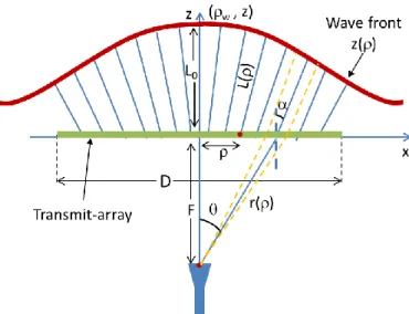
Consider the geometry shown in Fig. 1, which represents a transmit-array with 𝐷 diameter centered at the origin of the coordinate system, with its primary feed located at 𝑧 = − 𝐹. The transmit-array, illuminated by the known power radiation pattern of the feed 𝑈(𝜃), is required to transform it into the desired power radiation pattern 𝐺(𝛼), both considered axial-symmetric functions. The formulation’s underlying assumption is that, in the GO limit, the shape of the outgoing phase front radiated by the transmit-array is mostly sufficient to determine the shape of the far-field magnitude radiation pattern. The design process thus involves two practically independent steps:
• Determination of the directions 𝛼(𝜌) that each ray must follow when exiting each point 𝜌 of the transmit-array in order that, globally, the rays synthesize the desired 𝐺(𝛼) function.
• Determination of the relation between the obtained 𝛼(𝜌) function and the required phase distribution 𝜙𝑙𝑒𝑛𝑠(𝜌) over the transmit-array.
A. Determination of the rays exit angle 𝛼(𝜌) distribution
Consider an elementary ray tube (marked with a yellow dashed line in Fig. 1) originated at the feed phase center, and directed towards the transmit-array along an angle 𝜃. It defines an elementary solid angle sin 𝜃 𝑑𝜃 𝑑𝜑. After crossing the transmit-array, the ray tube is assumed to propagate along an angle 𝛼, defining the elementary solid angle sin 𝛼 𝑑𝛼 𝑑𝜑. Power conservation across this elementary ray tube on both sides of the transmit-array can be expressed, for an axial-symmetric problem, as [26]:
Fig. 1 – Geometry for the transmit-array design, showing the tranmit-array, the feed, the output rays and the output wave-front.
Function 𝑇 represents the power transmissivity across the intersected part of the transmit-array:
𝑇 =𝑈∥𝑡∥2+ 𝑈⊥𝑡⊥2 𝑈
𝑐𝑜𝑠(𝛼)
𝑐𝑜𝑠(𝜃) (2)
where 𝑡∥ and 𝑡⊥ are the field transmission coefficients of the transmit-array for each polarization and 𝑈∥ and 𝑈⊥ are the power radiation pattern of the feed for each polarization. Replacing (1) in (2) results:
(𝑈∥𝑡∥2+ 𝑈⊥𝑡⊥2 ) 𝑡𝑎𝑛(𝜃) 𝑑𝜃
= 𝐾 𝐺(𝛼) 𝑡𝑎𝑛(𝛼) 𝑑𝛼 (3) 𝐾 is a normalization constant to be determined from the power balance between the incident and transmitted waves: 𝐾 =∫ (𝑈∥𝑡∥ 2+ 𝑈 ⊥𝑡⊥2 ) 𝑡𝑎𝑛(𝜃) 𝑑𝜃 𝜃𝑚𝑎𝑥 0 ∫𝛼𝑚𝑎𝑥𝐺(𝛼) 𝑡𝑎𝑛(𝛼) 𝑑𝛼 0 (4)
𝛼𝑚𝑎𝑥 is the roll-off angle of the target radiation pattern when an abrupt drop is required, or the angle beyond which the radiation become negligible. 𝜃𝑚𝑎𝑥 is the maximum feed subtended angle defined as:
𝜃𝑚𝑎𝑥 = 𝑎𝑟𝑐𝑡𝑎𝑛 (𝐷
2𝐹) (5)
Equation (3) can be re-arranged to: 𝑑𝛼
𝑑𝜃=
(𝑈∥𝑡∥2+ 𝑈
⊥𝑡⊥2) 𝑡𝑎𝑛(𝜃)
𝐾 𝐺(𝛼) 𝑡𝑎𝑛(𝛼) (6)
Noting from Fig. 1 that 𝜌 = 𝐹 𝑡𝑎𝑛( 𝜃), it is possible to further re-write (6) as:
{ 𝑑𝛼 𝑑𝜌= (𝑈∥𝑡∥2+ 𝑈⊥𝑡⊥2) 𝐾 𝐺(𝛼) 𝑡𝑎𝑛(𝛼) 𝜌 𝐹2+ 𝜌2 𝛼(0) = 0 (7)
It is noted that transmission coefficients 𝑡∥ and 𝑡⊥ and the normalization constant K actually depend on transmit-array characteristics that are still to be defined in the second step of the design. However, as will be discussed ahead, the transmission coefficients may be very close to unity by design in transmit-arrays (better than −1 dB transmission in average of the cells that compose the transmit-array) and reasonably constant within the used 𝜃 range. This is enough to continue considering the two steps independently. Consideration of transmission coefficients dependence with 𝜃 is possible, and will be briefly discussed ahead. The integration of (7) with appropriate initial conditions concludes the first step of the design, providing the 𝛼(𝜌) function that ensures in the GO limit the desired far-field radiation pattern.
B. Exiting ray angle distribution and wave phase-front
It remains to establish the relation between the obtained exit angle distribution 𝛼(𝜌) and the required phase shift distribution 𝜙𝑙𝑒𝑛𝑠(𝜌) over the transmit-array. The rationale is that the knowledge of 𝛼(𝜌) immediately defines the output wave-front shape 𝑧(𝜌), since it is everywhere normal to the rays output direction, see the red curve in Fig. 1. Consequently, the path lengths 𝐿(𝜌) defined from the transmit-array surface to the wave-front (blue lines in Fig. 1) become uniquely determined from 𝑧(𝜌):
𝐿(𝜌) = 𝑧(𝜌)
𝑐𝑜𝑠(𝛼) (8)
By definition, the phase at the wave-front is constant, and given by:
𝑘0𝑟(𝜌) + 𝑘0𝐿(𝜌) + 𝜙𝑙𝑒𝑛𝑠(𝜌) = 𝐶 (9) where 𝑟(𝜌) is the distance from the feed phase center to a point in the transmit-array aperture, and 𝐶 is an arbitrary constant phase value. So, once 𝑧(𝜌) and 𝐿(𝜌) are known, the unknown 𝜙𝑙𝑒𝑛𝑠(𝜌) function can be calculated from (9).
Now to obtain 𝑧(𝜌) we note from Fig. 1 that 𝑑𝑧
where 𝜌𝑤 is a transformed radial coordinate associated with the wave-front
𝜌𝑤= 𝜌 + 𝑧 𝑡𝑎𝑛(𝛼) (11)
It is preferable to obtain 𝑑𝑧 𝑑𝜌⁄ instead, so that 𝜌 remains the only independent variable of the problem:
𝑑𝑧 𝑑𝜌= 𝑑𝑧 𝑑𝜌𝑤 𝑑𝜌𝑤 𝑑𝜌 (12)
Straightforward manipulations using (10) and (11) in (12), lend to: { 𝑑𝑧 𝑑𝜌= −𝑧 𝑑𝛼 𝑑𝜌𝑡𝑎𝑛(𝛼) − 𝑠𝑖𝑛(2𝛼) 2 𝑧(0) = 𝐿0 (13)
where 𝑑𝛼 𝑑𝜌⁄ is already defined in (7). Integration of (13) provides the wave-front shape 𝑧(𝜌).
In summary, once the feed power radiation pattern 𝑈(𝜃) and the output power pattern template 𝐺(𝛼) are defined as well as the transmit-array focal distance and side length, the transmit-array design involves the following steps:
1. Calculation of the 𝐾 constant using eq. (4), assuming constant or unit value for transmission coefficients 𝑡∥ and 𝑡⊥;
2. Integration of eq. (7) in the 𝜌 ∈ [0, 𝐷 2⁄ ] interval, to determine 𝛼(𝜌), using the initial condition 𝛼(0) = 0;
3. Integration of eq. (13) in the same 𝜌 ∈ [0, 𝐷 2⁄ ] interval, to determine 𝑧(𝜌), using the initial condition 𝑧(0) = 𝐿0, where L0 is an arbitrary
constant defined in Fig. 1.
4. Calculation of the lens phase distribution 𝜙𝑙𝑒𝑛𝑠(𝜌) to be introduced by the transmit-array, using eqs. (8) and (9). The value of the constant C in (9) is adjusted according to a desired starting value for 𝜙𝑙𝑒𝑛𝑠(𝜌) at 𝜌 = 0.
It is noted that the solution is the result of a closed-form evaluation of two differential equations. However, if 𝑡∥2 and 𝑡⊥2 are found to be noticeably less than unity after selecting the transmit-array’s unit cells that define the wanted 𝜙𝑙𝑒𝑛𝑠(ρ) function in step 4, then its values must be replaced in eqs. (1) to (7) and the process repeated from steps 1 to 4 until convergence. Assuming that an effort is made to keep 𝑡∥ and 𝑡⊥ close to unity in all unit-cells to favor transmission efficiency, which is the underlying goal of this formulation, none or only up to three iterations are usually needed. Note that the result of each iteration
is still obtained as a closed-form solution of differential equations, and not from intensive global parameter optimization as in [25]. No iteration was required in the example dealt ahead.
It is also noted that the synthesis formulation itself is general and independent of the type of unit cells used to implement the phase shifting transmit-array. The validity of the formulation must be considered separately from the effect of different possible unit-cell realizations.
III. UNIT CELL DESIGN
An array of phase-delay [20] or phase rotation [27] cells can be used to physically implement a prescribed phase-shift function over an aperture. These cells behave locally as effective refractive index media blocks, each one adding a prescribed phase lag to the transmitted rays, according to the desired 𝜙𝑙𝑒𝑛𝑠(𝜌) distribution. In this work, we reuse the phase delay cells presented in [17] for the 30 GHz band. It is noted that the formulation from the previous section is independent of the type of phasing cell that is used.
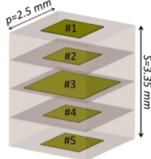
The used unit cells are formed by five stacked square metal patches separated by four layers of Duroid 5880 with 0.787 mm thickness, r = 2.2 and loss tangent
𝑡𝑎𝑛𝛿 = 0.0009, Fig. 2. The cell height is S = 3.35 mm counting with metal thickness. The cell side is 𝑝 = 2.5 mm, corresponding to /4 at 30 GHz. The difference from cell to cell is the size of the patch inclusions. All cells present 𝑧-plane symmetry, meaning that patch #1 and #5 are equal and patch #2 and #4 are equal. This configuration provides the necessary degrees of freedom to optimize the phase response, transmissivity and bandwidth. Due to its in-plane symmetry, the cell is adequate for circular polarization. 63 different unit-cells were designed to cover a 330º phase shift range with near 5º steps, according with [17].
The cell with the smallest metal fraction area is used as the phase reference. Transmission coefficient values for the different cells are not listed here, but all are better than ‒0.4 dB [17], considering normal incidence, which
Fig. 2 – Basic unit cell composition with 5 patches embedded in dielectric.
enables considering 𝑡∥2 ≈ 1 and 𝑡⊥2≈ 1 in equation (6). For 30º of oblique incidence, the transmission coefficient all the cells are better than -1dB.
IV. TRANSMIT-ARRAY IMPLEMENTATION
A. Design
The target power pattern selected to illustrate the method is the classical constant flux template
{
𝐺(𝛼) = sec2𝛼, |𝛼| ≤ 𝛼 𝑚𝑎𝑥
𝐺(𝛼) = 0, |𝛼| > 𝛼𝑚𝑎𝑥 (14)
here with 𝛼𝑚𝑎𝑥= 45° roll-off and circular polarization. In order not to mask the results with the non-ideal axial ratio of a real circular polarized feed, the transmit-array illumination is synthesized by post-processing the results of two consecutive rectangular horn orthogonal positions at the transmit-array focal point, with phase quadrature. The feed power pattern in Equation (3) needs to be exactly axial-symmetric, so a best-fit function has to be defined. One simple form is:
𝑈(𝜃) = 𝑒−(𝜃/𝜎)𝑚
(15) where 𝜎 and 𝑚 are shape parameters, which ensures very fast evaluation of steps 1) to 4) from the previous section. Other simple forms like raised cosine would be possible.
Design parameters to be defined are the transmit-array side length 𝐷, its focal distance 𝐹, and the feed full beam width. The larger is 𝐷 compared to 𝜆, the better is the compliance with the target radiation pattern, with little change in directivity. This is different from collimating-beam antennas, where an aperture size increase normally corresponds a monotonic directivity increase. Also increasing 𝐹 tends to slow the variation of the required phase correction function 𝜙𝑙𝑒𝑛𝑠(𝜌) over the transmit-array; this is highly desirable because too many 2𝜋 phase jumps at the aperture reduce the space to fit-in enough cells to adequately represent the phase function. Of course, antenna compactness calls for reduced 𝐷 and 𝐹, so a compromise must be found. Finally, the full beam width of the feed at 𝜃𝑓𝑒𝑒𝑑 = 2 𝜃𝑚𝑎𝑥 must comply with an edge taper illumination condition. Simulations showed that values lower than -10 dB produce the best results for this kind of target power radiation pattern.
For the illustration example, the square transmit-array size is set to 𝐷 = 180 mm (18-𝜆 at 30 GHz). The selected focal distance 𝐹 = 60 mm is close to the minimum value that avoids 2𝜋 phase jumps at the aperture. From the definition of F and D, applying equation (5), results a
maximum feed subtended angle (𝜃𝑚𝑎𝑥) of 56°. With the definition of F, D, 𝛼𝑚𝑎𝑥 and 𝜃𝑚𝑎𝑥, the normalization constant, K, can be determined from (4) and is equal to 0.355. The rectangular horn aperture dimensions are 8.98 mm by 11.587 mm with a flange length of 20.35 mm, producing a far-field gain of 10.8 dBi with equal E- and H-plane radiation patterns. The phase center is almost coincident in both planes and located 1.26 mm inside the horn aperture. This far-field radiation pattern is used at the design stage as an approximation, although knowing that 𝐹 is smaller than the far-field distance and some interaction may exist between the transmit-array and the horn. Its impact will be evaluated by full-wave analysis in Section IV.B.
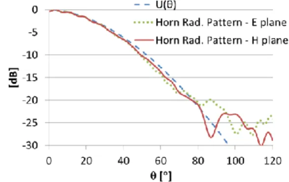
A good analytical fit of the radiation pattern using (15) is obtained for = 33°, m = 1.8. Fig. 3 shows the
superposition of the full-wave horn radiation pattern (for E- and H-plane) with the fitting function (15). As shown in Fig. 3 the -10dB feed full beam width is close to the desired 𝜃𝑓𝑒𝑒𝑑⁄ = 𝜃2 𝑚𝑎𝑥 = 56º.
Fig. 3 – Horn antenna radiation pattern for the main planes and corresponding fitting function at 30 GHz.
The output ray tilt distribution 𝛼(𝜌) is calculated from (7) considering unit transmissivity. The result is shown in Fig. 4. As could be anticipated, the rays tilt away from the axial region with increasing 𝜌 to divert radiation into the 𝛼𝑚𝑎𝑥 direction, the asymptote in the figure. The calculated 𝛼(𝜌) is used in equations (8) and (9) to generate the required phase distribution 𝜙𝑙𝑒𝑛𝑠(𝜌) at the transmit-array, Fig. 5.
A Physical Optics (PO) tool can be used at this point to very quickly anticipate the radiation pattern of this aperture with known phase 𝜙𝑙𝑒𝑛𝑠(𝜌) and amplitude 𝐺[𝛼(𝜌)] distribution. This allows making fine adjustments in 𝐷, 𝐹 or the feed directivity, before embarking in the computationally heavy full-wave analysis that is.
Fig. 4 – Output ray tilt 𝛼(𝜌) versus the radial distance over the transmit-array surface.
B. Analysis
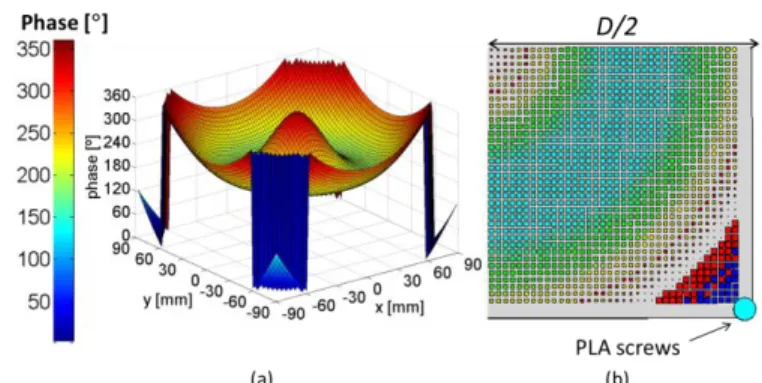
Fig. 5 superimposes the calculated phase function 𝜙𝑙𝑒𝑛𝑠(𝜌) with the phase of selected cells from the set described in Section III. Each dot corresponds to one cell and each cell shows its own phase at 30 GHz. A very good correspondence is found between the cell’s phase and the required phase 𝜙𝑙𝑒𝑛𝑠(𝜌). This radial phase (and cell) distribution is repeated for all 𝜑-angles, as represented in Fig. 6(a). Actually, the transmit-array edges are cut square to facilitate its construction, being thus formed by 72 × 72 cells. The top-view of the transmit-array is shown in Fig. 6(b), with the cells colored according to its phase value at the nominal frequency. The dielectric is extended 1 cm beyond the cell-populated area to provide space to fix the transmit-array to the mounting structure.
Fig. 5 – Resulting transmit-array phase and cell distribution using the unit cells described in Section III.
Fig. 6 – Phase distribution (a) and corresponding cell arrangement for a quarter of the lens (b).
CST microwave studio [28] is used to perform the full-wave simulation of the structure. The simulation model includes the full cell structure details. Two plane symmetries are used to reduce the computation time. Even so, due to the extreme meshing detail required to characterize the unit-cells adequately, and the overall size of the computation volume, the available RAM in the simulation platform in part limits the simulation accuracy. It impacts mainly on cross-polarization, and back-reflection estimation.
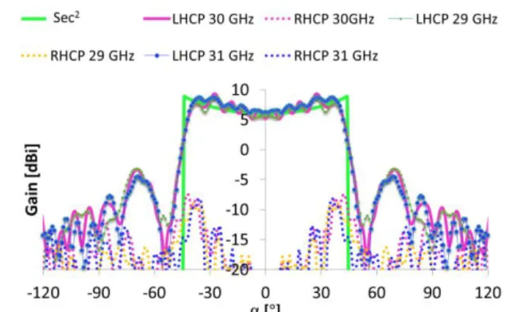
The antenna radiation pattern is presented in Fig. 7 for 29 GHz, 30 GHz and 31 GHz. Actually, in each case it is a composition of the results obtained for two orthogonal orientations of the rectangular horn with phase quadrature, to generate the transmit-array response to left-hand circular polarization (LHCP) excitation. The co-polar radiation patterns (solid lines) follow reasonably well the sec2 template (solid green line). The cross-polarization level (dotted lines) is better than 15 dB, the worst value being found near 𝛼𝑚𝑎𝑥=45º.
Fig. 7 additionally shows a reasonably stable radiation pattern over 2 GHz bandwidth. On one side, this is a consequence of the GO-based formulation, which is intrinsically frequency independent, as long as the aperture size is at least 10-20 lambda. Therefore, the frequency dependence is dominated by the feed and the unit cells. On the other side, the stable radiation pattern over the 2 GHz interval is an indication that feed and the unit-cells have a matching bandwidth. The simulated radiation efficiency of the designed transmit-array is 90%. The side-lobe level is about 10 dB. This relatively high value does not result from any limitation of the proposed synthesis method, but rather from the non-ideal response of the transmit-array cells. Its imperfect reflection coefficient for high incidence angle favors, in this example, a propagating wave at the bottom part of the transmit-array that diffracts at the aperture edge towards 70º (marked with white ellipses in Fig, 8). No contribution is seen from the near-field above the transmit-array towards the side-lobe direction. In order to support this claim, Fig. 9 shows the PO radiation pattern associated with the aperture fields calculated using two different approaches. In the solid line radiation pattern, the aperture field distribution is obtained from the GO synthesis method. In the dashed line radiation pattern the aperture fields are obtained from the original full-wave problem, but the PO integration is restricted to the transmit array top aperture only. In both cases, the SLL is minimized, thus confirming that its origin is not related to the synthesis method. The unit-cell optimization to reduce the SLL is out of the scope of the present paper.
Fig. 7 - Full-wave simulated radiation pattern of the transmit-array at 29 GHz, 30 GHz and 31 GHz with circular polarization in φ=0˚
plane.
Fig. 8 – Full-wave simulated near-field of the transmit-array at 30 GHz, showing the edge diffraction contribution, in φ=0˚ plane.
Fig. 9 - PO radiation pattern of the transmit-array at 30 GHz with circular polarization in φ=0˚ plane. Solid lines: aperture fields obtained from the GO synthesis method. Dashed lines: aperture fields obtained from the original full-wave problem,
but the PO integration is restricted to the transmit array aperture only.
V. MEASUREMENTS AND RESULTS
A 10.8 dB rectangular horn was fabricated with the dimensions indicated in Section IV.A. The horn was integrated into a dedicated 3D-printed PLA structure (r =
2.93 and a loss tangent of tan𝛿=0.0121 @ 40GHz, [29]) designed to hold precisely the transmit-array in front of the horn at the correct 𝐹 distance, see Fig. 10. These legs are hollow to reduce its influence on the feed radiation
pattern. Measurements of the horn radiation pattern with and without the lens support showed no significant impact from the structure.
Fig. 10 – Measurement setup showing the feeding horn and the transmit-array mounted on the support.
The antenna prototype was fabricated using the same process described in detail at [17]. The metal patterning of each dielectric layer was obtained by photolithographic process. The DUROID layers were bonded using ROGERS 3001 bonding layer, with the appropriate pressure and temperature cycle. For the measurements in the anechoic chamber, the transmit-array was fixed to the PLA support structure at its corners, with minimum perturbation of the feed illumination path, Fig. 10.
Fig. 11 - Simulated and measured transmit-array radiation pattern including the support structure at 30 GHz, in φ=0˚ plane.
Measurements were carried out for two orthogonal linear polarizations, in order to retrieve by post-processing the transmit-array radiation pattern, when illuminated by a perfect circular polarization feed. Post-processed measured and simulated results are superimposed in Fig. 11. The agreement is quite good for the co-polar component (left-hand circular polarization LHCP) showing a well-defined roll-off at 45˚. The ripple in the center of the LHCP measured radiation pattern is similar to the simulated one, remaining below 2 dB. The side lobe level of the measured and simulated curves is also comparable. Regarding the cross-polarization level, the measured results are curiously much better than
simulation. This can be attributed to the previously mentioned insufficient numerical resources to reach the best simulation accuracy.
These good results validate the proposed design formulation and the transmit-array implementation.
VI. CONCLUSIONS
The paper proposes an analytical formulation to synthesize a shaped radiation pattern using a planar transmit-array. Transmit-arrays are thin, low weight and potentially low-cost structures, flexible to accommodate different radiation pattern requirements, making them attractive aperture antennas. Since their operation is based on phase shifting principles, the satisfaction of a power pattern template requires finding the right correspondence between the output power pattern and the phase distribution over the transmit-array surface. This paper shows that this relation is possible under certain conditions, and that the transmit-array design can be obtained directly as a solution of two first-order differential equations, without iterations. The design does not require any insertion or reflection loss at the unit cell level, which favors maximum transmission through the transmit-array. It only requires an appropriate phase distribution over the aperture. This contrasts with an alternative approach reported in the literature [23] that requires both amplitude and phase shifting unit-cells, and uses an iterative approach to reach the template.
The new formulation is used to produce, as an example, a secant-squared power pattern at the 30 GHz Ka-band, with a steep roll-off at 45º. The transmit-array is 3.35 mm thick, 180 mm × 180 mm in-plane dimensions, with 60 mm focal distance. It is fed by a synthesized source with circular polarization, and the measured results agree quite well with the target template. The simulated radiation efficiency of the designed transmit-array is 90%. The results are much better than the few that are available in the literature.
The formulation is general and it works with other power templates, if the aperture is much larger than the wavelength. However, the particular implementation of the phase-shifting unit-cells determines the final antenna performance and may limit the ideal transmit-array response.
The principle behind the presented formulation can be generalized for non-axial symmetric problems.
ACKNOWLEDGMENT
The authors acknowledge the collaboration from J. Farinha and C. Brito for the prototype construction and A. Almeida for creating the 3D printed accessories and for the measurements. Also, a special thank is due to João M. Felício for the support during the fabrication process.
REFERENCES
[1] M. Mahajan, R. Jyoti, K. Sood, and S. B. Sharma, “A method of generating simultaneous contoured and pencil beams from single shaped reflector antenna”, IEEE Trans. Antennas Propag, vol. 61, no. 10, pp. 5297-5301, Jun., 2013.
[2] P. Lacomme, J-R Hardange, J-C. Marchais, and E. Normant, “Ground Mapping” in Air and Spaceborne Radar Systems, 1st ed.,
Norwich, New York, USA: William Andrew Publishing, 2001, ch. 13, sec. 13.2.2, pp. 202-203.
[3] M. Lapointe, G. Seguin and J.-J. Laurin, “Integrated beam synthesis and performance analysis of a spaceborne SAR antenna”, IEEE Antennas Propag. Mag., vol. 48, no. 3, pp. 55-61, Jun. 2006.
[4] Morten Tolstrup, Indoor Radio Planning: A Practical Guide for
GSM, DCS, UMTS, HSPA and LTE,2nd ed.,, Jul., 2011.
[5] C. A. Fernandes, “Shaped dielectric lenses for wireless millimeter wave communications”, IEEE Antennas Propag. Mag., vol. 41, no. 5, pp. 141-150, Oct. 1999.
[6] R. Eirey-Pérez, J. A. Rodríguez-González, and F. J. Ares-Pena, “Synthesis of Array Radiation Pattern Footprints using Radial Stretching, Fourier Analysis, and Hankel Transformation,” IEEE
Trans. Antennas Propag, vol. 60, no. 4, pp. 2106-2109, Apr,
2012.
[7] R. Eirey-Pérez, A. A. Salas-Sánchez, J. A. Rodríguez-González, and F. J. Ares-Pena, “Pencil Beams and Flat-Topped Beams with Asymmetric Sidelobes from Circular Arrays”, IEEE Antennas
Propag. Mag., vol.56, no. 6, pp. 153-161, Dec., 2014.
[8] R. A. Penchel, J. R. Bergmann, and F. J. S. Moreira, “Main-Reflector Shaping of Omnidirectional Dual “Main-Reflectors Using Local Conic Sections”, IEEE Trans. Antennas Propag., vol. 61, no. 8, pp. 4379-4383, Aug., 2013.
[9] S. Landeros, R. Neri, and R. Samano, “A Tutorial on the Synthesis of Single Shaped Reflectors in C KU and KA Bands”,
Electromagnetics, vol. 26, no. 2, pp. 131-154, Aug., 2006.
[10] R. Sauleau and B. Barès, “A complete procedure for the design and optimization of arbitrarily-shaped integrated lens antennas”,
IEEE Trans. Antennas Propag, vol. 54, no. 4, pp. 1122-1133,
Apr. 2006.
[11] G. Godi, R. Sauleau, L. Le Coq, D. Thouroude, "Design and optimization of three dimensional integrated lens antennas with genetic algorithm", IEEE Trans. Antennas Propag., vol. 55, no. 3, pp. 770-775, Mar. 2007.
[12] B. Chantraine-Barès, R. Sauleau, L. L. Coq, and K. Mahdjoubi, “A new accurate design method for millimeter-wave homogeneous dielectric substrate lens antennas of arbitrary shape,” IEEE Trans. Antennas Propag., vol. 53, no. 3, pp. 1069– 1082, Mar. 2005.
[13] C. A. Fernandes and L. M. Anunciada, "Constant flux illumination of square cells for millimeter-wave wireless communications", IEEE Trans. Microw. Theory Techn., vol. 49, no. 11, pp. 2137-2141, Nov. 2001.
[14] E. Carrasco, M. Barba, J.A. Encinar, M. Arrebola, F. Rossi, and A. Freni, “Design, manufacture and test of a low-cost shaped-beam reflectarray using a single layer of varying-sized printed dipoles,” IEEE Trans. Antennas Propag., vol. 61, no. 6, pp. 3077– 3085, Jun., 2013
[15] J. A. Encinar and J. A. Zornoza, "Three-layer printed reflectarrays for contoured beam space applications", IEEE Trans. Antennas
Propag., vol. 52, no. 5, pp. 1138-1148, May 2004.
[16] L. Di Palma, A. Clemente, L. Dussopt, R. Sauleau, P. Potier, and P. Pouliguen, “Radiation Pattern Synthesis for Monopulse Radar Applications With a Reconfigurable Transmitarray Antenna,”
IEEE Trans. Antennas Propag., vol. 64, no. 9, pp. 4148-4154,
Sep. 2016.
[17] E. B. Lima, S. A. Matos, J. R. Costa, C. A. Fernandes, and N. J. Fonseca, "Circular polarization wide-angle beam steering at
Ka-band by in-plane translation of a plate lens antenna", IEEE Trans.
Antennas and Propag., vol. 63, no. 12, pp. 5443-5455, Dec. 2015.
[18] A. H. Abdelrahman, Fan Yang, Atef Z. Elsherbeni, and P. Nayeri, “Introduction” in Analysis and Design of Transmitarray
Antennas, 1st ed., San Rafael, CA, USA, Morgan & Claypool
Publishers, 2017, ch. 1, sec. 1.1, pp 1-7.
[19] N. Gagnon, A. Petosa, and D. A. McNamara, “Printed Hybrid Lens Antenna,” IEEE Trans. Antennas and Propag., vol. 60, no. 5, pp. 2514 – 2518, May 2012.
[20] S. A. Matos, E. B. Lima, J. S. Silva, J. R. Costa, C. A. Fernandes, N. J. Fonseca, and J. R. Mosig, "High Gain Dual-Band Beam Steering Transmit-array for Satcom Terminals at Ka Band.",
IEEE Trans. Antennas Propag., vol. 65, no. 7, pp. 3528-3539,
Jul., 2017.
[21] N. Gagnon and A. Petosa, “Using Rotatable Planar Phase Shifting Surfaces to Steer a High-Gain Beam,” IEEE Trans. Antennas
Propag., vol. 61, no. 6, pp. 3086-3092, Jun, 2013.
[22] R. A. Petosa, S. Thirakoune, and A. Ittipiboon, "Investigation on arrays of perforated dielectric Fresnel Lens", Proc. IEEE Microw.
Antennas Propag., vol. 153, no. 3, pp. 270-276, Jun., 2006.
[23] N. Gagnon, A. Petosa, and D. A. McNamara, “Electrically Thin Free-Standing Phase and Amplitude Shifting Surface for Beam Shaping Applications”, Microwave and Optical Technology
Letters, Vol. 54, no. 7, pp. 1566-1571,Jul., 2012
[24] N. Gagnon, A. Petosa, and D. A. McNamara, “Research and development on phase-shifting surfaces”. IEEE Antennas
Propag. Mag., vol. 55, no. 2, pp. 29–48, Apr., 2013.
[25] R. S. Elliott and G. J. Stern, “Shaped Patterns from a Continuous Planar Aperture Distribution,” Proc. IEEE H – Microwaves,
Antennas and Propag., vol. 135, no. 6, pp. 366-370 Dec., 1988.
[26] C. Salema, C. A. Fernandes, R. K. Ja, Solid Dielectric Horn
Antennas, Artech House, Boston, 1998
[27] P. Naseri, F. Khosravi, and P. Mousavi, “Antenna-Filter-Antenna-Based Transmit-Array for Circular Polarization Application,” IEEE Antennas Wireless Propag. Lett., vol. 16, pp. 1389-1392, Dec. 2016.
[28] CST—Computer Simulation Tech, Nov. 2016 [Online]. Available: http://www.cst.com .
[29] J. Felício, C. A. Fernandes, and J. R. Costa, “Complex Permittivity and Anisotropy Measurement of 3D-Printed PLA at Microwaves and Millimeter-waves,” International Conf. on Appl.
Electromagnetics and Communications - ICECOM, Dubrovnik,
Croatia, pp. 1-6, Sept. 2016.
Catarina C. Cruz was born in Lisbon, Portugal, in 1986. She received the Licenciado and the M.Sc. degrees in telecommunications engineering and computer science from the Instituto Universitário de Lisboa (ISCTE-IUL), Lisbon, in 2009 and 2011, respectively. She is currently working toward the Ph.D. degree at the Instituto Superior Técnico (IST), Technical University of Lisbon, Lisbon. Since 2011, she has been a Researcher with the Instituto de Telecomunicações (IT), focusing her work on antennas for wireless communications. Her current research interests are in the area of antennas for radio-frequency identification (RFID), dielectric antennas for millimeter wave applications, antennas and propagation modeling for communication systems and lenses. She is also an invited Lecturer at the Departamento de Ciências e Tecnologias da Informação, Instituto Universitário de Lisboa (ISCTE-IUL).
Sérgio A. Matos received the Licenciado, M.Sc., and Ph.D. degrees in electrical and computer engineering from Instituto Superior Técnico (IST), University of Lisbon, Lisbon, Portugal, in 2004, 2005, and 2010, respectively. He is currently a Researcher with the Instituto de Telecomunicações (IT), Lisbon, Portugal. He is also an Assistant Professor at the Departamento de Ciências e Tecnologias da Informação, Instituto Universitário de Lisboa (ISCTE-IUL). He is the co-author of 55 technical papers in international journals and conference proceedings. His present research interests include electromagnetic wave propagation in metamaterials, flat-lens design and transmit-arrays.
Jorge R. Costa (S’97–M’03–SM’09) was born in Lisbon, Portugal, in 1974. He received the Licenciado and Ph.D. degrees in electrical and computer engineering from the Instituto Superior Técnico (IST), Technical University of Lisbon, Lisbon, Portugal, in 1997 and 2002, respectively.
He is currently a Researcher at the Instituto de Telecomunicações, Lisbon, Portugal. He is also an Associate Professor at the Departamento de Ciências e Tecnologias da Informação, Instituto Universitário de Lisboa (ISCTE-IUL). His present research interests include lenses, reconfigurable antennas, MEMS switches, UWB, MIMO and RFID antennas. He is the coauthor of four patent applications and more than 150 contributions to peer reviewed journals and international conference proceedings. More than thirty of these papers have appeared in IEEE Journals. Prof. Costa served as an Associate Editor for the IEEE Transactions on Antennas and Propagation from 2010 to 2016 and he was a Guest Editor of the Special Issue on “Antennas and Propagation at mm- and Sub mm-Waves”, from the IEEE Transactions on Antennas and Propagation, April 2013. He was the Co-Chair of the Technical Program Committee of the European Conference on Antennas and Propagation (EuCAP 2015) in Lisbon and General Vice-Chair of EuCAP 2017 in Paris.
Carlos A. Fernandes (S’86–M’89–SM’08) received the Licenciado, MSc, and PhD degrees in Electrical and Computer Engineering from Instituto Superior Técnico (IST), Technical University of Lisbon, Lisbon, Portugal, in 1980, 1985, and 1990, respectively. He joined IST in 1980, where he is presently Full Professor at the Department of Electrical and Computer Engineering in the areas of microwaves, radio wave propagation and antennas. He is a senior researcher at the Instituto de Telecomunicações and member of the Board of Directors. He has co-authored a book, a book chapter, more than 150 technical papers in peer reviewed international journals and conference proceedings and 7 patents in the areas of antennas and radiowave propagation modeling. His current research interests include dielectric antennas for millimeter wave applications, antennas and propagation modeling for personal communication systems, RFID and UWB antennas, artificial dielectrics and metamaterials. He was a Guest Editor of the Special Issue on “Antennas and Propagation at mm- and Sub mm-Waves”, from the IEEE TRANSACTIONS ON ANTENNAS AND PROPAGATION, April 2013.