DYNAMIC BEHAVIOUR AND FATIGUE ASSESSMENT OF
RAILWAY BRIDGE DECK SLABS
Joel Pedro da Conceição Malveiro
2017
A dissertation presented to the Faculty of Engineering of the University of Porto for the degree of Doctor in Civil Engineering.
Supervisor: Prof. Rui Calçada (FEUP, Portugal) Co-Supervisor: Prof. Carlos Sousa (FEUP, Portugal)
“All of our days are numbered. We cannot afford to be idle.
To act on a bad idea is better than to not act at all. Because the worth of the idea never becomes apparent, until you do it.
Sometimes, this idea can be the smallest thing in the world, a little flame that you hunch over and cup with your hand... and pray will not be extinguished
by all the storm that howls about it. If you can hold on to that flame,
great things can be constructed around it...
things that are massive and powerful and world changing. All held up by the tiniest of ideas.”
Nick Cave (in 20,000 days on Earth)
“Há tempo para tudo e há um tempo para tudo.”
Abstract
A considerable growth in the railway system has been made during the last decade, either due to the introduction of new high-speed lines, and the modernisation of the existing ones, or due to the improvement of freight trains service on the classical network. This development only has been possible owing the construction of a significant number of bridges and viaducts, where distinct structural solutions have been implemented in its construction. Among them are I-shaped or U-shaped girders connected on the top by a reinforced concrete slab. This type of structures is related to the use of prestressed concrete or steel plates as main girders in the longitudinal direction. Furthermore, these reinforced concrete slabs present a low thickness and a low reinforcement rate, reason why they appear as being the most susceptible structural element to the occurrence of cracking and consequently to fatigue damage.
Since a high number of loading cycles can occur, due to the passage of railway traffic at different speeds, which typically exceeds 10 million over the total life of the structure, this thesis focuses on the evaluation of the local behaviour of these reinforced concrete slabs in railway viaducts. The analysis of this local behaviour reveals to be more complex rather than the analysis of the main girders, the latter associated with a global behaviour of the structure and usually being dominated by the first global vibration modes. Bearing this in mind, this thesis aims at giving a contribution to understand the real performance of this structural element. Particular attention was given to the development and validation of numerical models, based on the measurement of real responses, for the calculation of internal efforts in the slab. A realistic estimate of these internal efforts is a paramount step for carrying out a fatigue assessment of the structure.
Two different railway viaducts, with typical solutions widely employed in the construction of railway structures, are considered in the present thesis: i) a U-shaped precast and
girders connected on the top by a reinforced concrete slab.
In both cases, detailed numerical analyses are performed. For that purpose, three-dimensional numerical models of the viaducts and trains are used. A calibration methodology of numerical models is used, taking into account an optimisation method through a genetic algorithm and based on modal information experimentally obtained. The natural frequencies and mode shapes, both related to the global behaviour of the structures and to the local behaviour of the upper slabs, obtained via ambient vibration tests, are compared with the calculated ones.
Dynamic numerical responses, taking into account the interaction between the train and the bridge, are experimentally validated through the comparison with the real structural performances that are measured under railway traffic. Throughout the thesis, the influence of some relevant parameters is analysed and discussed, such as the modal damping coefficients, the stiffness of the bearings, the track irregularities, the train speed and the cut-off frequency considered in the analysis of each response variable.
In order to get more realistic results, a static correction procedure is employed, and validated, to account for the static contribution of vibration modes of higher frequencies, which are not explicitly considered in the basic modal-superposition method (used to solve the dynamic problem). Concerning the modal damping coefficients of local vibration modes of the RC deck slabs, a methodology based on the measurement of the slab’s dynamic responses under railway traffic is implemented to identify accurate damping values, related to the vibration levels corresponding to the passage of trains, instead of using the values provided by ambient vibration tests.
Finally, based on the results of different train-bridge interaction dynamic analyses, the assessment of the fatigue resistance in the transverse reinforcement bars of upper deck slabs is performed. Taking into account the effects of the aforementioned parameters, the fatigue damage is calculated as well as the required reinforcement area to get a fatigue life equal to 100 years.
Resumo
Na última década tem-se registado um crescimento considerável no que diz respeito ao transporte ferroviário, seja devido ao desenvolvimento de novas linhas de alta velocidade, ou mesmo a modernização das existentes, ou devido à melhoria do serviço de transporte de mercadorias nas linhas convencionais. Este desenvolvimento só tem sido possível com recurso à construção de um significativo número de pontes e viadutos, nas quais diversas soluções estruturais têm sido empregues. Entre elas há a destacar a construção de tabuleiros com vigas I ou vigas U, ligadas superiormente por lajes de betão armado. Este tipo de estruturas está associado ao uso de longarinas de betão pré-esforçado ou vigas metálicas na direção longitudinal. Para além disso, estas lajes de betão armado apresentam uma espessura reduzida e uma baixa taxa de armadura, razão pela qual aparecem como sendo o elemento mais suscetível à ocorrência de fendilhação e, consequentemente, de dano por fadiga.
Uma vez que estas estruturas podem estar sujeitas a um elevado número de ciclos de carregamento, que normalmente excede os 10 milhões de ciclos ao longo de toda a vida da estrutura, a presente tese foca-se na avaliação do comportamento local destas lajes de betão armado em tabuleiros ferroviários. A análise deste comportamento local revela-se mais complexa do que a análise das vigas principais, estas últimas associadas a um comportamento global da estrutura e geralmente dominado pelos primeiros modos de vibração globais. Neste sentido, esta tese tem como objetivo contribuir para a interpretação do desempenho real deste elemento estrutural. Foi dada particular atenção ao desenvolvimento e validação de modelos numéricos, com base em respostas realmente medidas, a usar no cálculo dos esforços internos da laje. Uma estimativa realista destes esforços internos é um passo fundamental para uma avaliação cuidada da fadiga da estrutura.
Dois viadutos ferroviários, com soluções amplamente empregues na construção deste tipo de estruturas, são analisados no presente estudo: i) viga U pré-fabricada e pré-esforçada, a
superiormente por uma laje de betão armado.
Em ambos os casos procedeu-se à realização de cuidadas análises numéricas. Para tal, recorreu-se ao uso de complexos modelos tridimensionais tanto das pontes como do comboio. A calibração dos modelos numéricos foi realizada com base na aplicação de um algoritmo genético e recorrendo a informação modal obtida experimentalmente. Quer as frequências naturais quer a configuração dos modos de vibração, relativas tanto ao comportamento global da estrutura como ao comportamento local da laje, foram obtidas através de ensaios de vibração ambiental e comparadas com os resultados obtidos por via numérica.
As respostas dinâmicas obtidas por via numérica, tendo em conta a interação entre ponte e comboio, foram validadas através da comparação com as respostas medidas experimentalmente sob ação de tráfego ferroviário. De forma a otimizar esta comparação, ao longo deste trabalho foi avaliada e discutida a influência de diversos parâmetros, tais como os coeficientes de amortecimento modais, a rigidez dos aparelhos de apoio, as irregularidades da via, a velocidade do comboio e a frequência de corte a considerar nas demais análises.
De forma a obter resultados mais realistas, procede-se à implementação e validação de um procedimento de correção estática de forma a assegurar pelo menos a contribuição estática dos modos de vibração com frequências mais elevadas, os quais não são explicitamente considerados na usual aplicação do método de sobreposição modal (usado para a resolução do problema dinâmico). No que diz respeito aos coeficientes de amortecimento dos modos de vibração locais, foi implementada uma metodologia, baseada na medição da resposta dinâmica da laje sob acção de tráfego ferroviário, com vista à identificação de valores mais precisos, os quais estão relacionados com níveis de vibração correspondentes à passagem de comboios em vez de recorrer a valores associados a níveis de vibração ambiental.
Finalmente, com base nos resultados das demais análises dinâmicas com interação ponte-comboio, é realizada a avaliação da resistência à fadiga da armadura transversal da laje superior do tabuleiro. Tendo em conta os efeitos dos parâmetros anteriormente referidos, procede-se ao cálculo do dano por fadiga assim como da área de armadura necessária para obter uma vida útil de fadiga igual a 100 anos.
List of Publications
The following publications were performed throughout the development of the present work:
International scientific journals
Malveiro, J., Ribeiro, D., Calçada, R., Delgado, R. (2014). Updating and validation of the dynamic model of a railway viaduct with precast deck. Structure and Infrastructure Engineering, 10 (11), 1484-1509.
Malveiro, J., Sousa, C., Ribeiro, D., Calçada, R. (2017). Impact of track irregularities and damping on the fatigue damage of a railway bridge deck slab. Structure and Infrastructure Engineering, DOI:10.1080/15732479.2017.1418010 (published online).
Malveiro, J., Ribeiro, D., Sousa, C., Calçada, R. (2018). Model updating of a dynamic model of a composite steel-concrete railway viaduct based on experimental tests. Engineering Structures, 164, 40-52.
International conference proceedings
Malveiro, J., Ribeiro, D., Calçada, R. (2011). Dynamic monitoring of a railway viaduct with precast deck. In EVACES’11 – International Conference on Experimental Vibration Analysis for Civil Engineering Structures. Varenna, Italy. Malveiro, J., Ribeiro, D., Calçada, R., Delgado, R. (2013). Updating and validation
of the finite element model of a railway viaduct based on dynamic tests. In IOMAC’13 – 5th
International Operational Modal Analysis Conference. Guimarães, Portugal.
CILAMCE2014 – XXXV Iberian Latin American Congress on Computational Methods in Engineering. Fortaleza, Brasil.
Malveiro, J., Sousa, C., Ribeiro, D., Calçada, R. (2015). Dynamic analysis for fatigue assessment of reinforced concrete slabs in railway viaducts. In MSLB2015 – Multi-span Large Bridges Conference. Porto, Portugal.
Malveiro, J., Sousa, C., Ribeiro, D., Calçada, R. (2016). Influence of track irregularities in the global and local dynamic response of precast decks under railway traffic loads. In IABMAS2016 – 8th International Conference on Bridge Maintenance, Safety and Management. Foz do Iguacu, Brasil.
National conference proceedings
Malveiro, J., Ribeiro, D., Sousa, C., Calçada, R, (2011). Identificação experimental dos parâmetros modais de um viaduto ferroviário com tabuleiro pré-fabricado. In ASCP’11 – Congresso Nacional sobre Segurança e Conservação de Pontes. Coimbra, Portugal
Acknowledgments/Agradecimentos
I would like to take this opportunity to express my gratitude to everyone who supported me throughout this academic accomplishment, which was only possible with their powerful guidance, invaluably constructive criticism and friendly advices during these years. To all of them I convey my sincere thanks:
To my supervisor, Professor Rui Calçada, to whom I am grateful for the encouragement and support given to develop this work. His enthusiasm about the railways and his huge knowledge about the dynamic behaviour of structures guided me since my first steps in this research field;
To my co-supervisor, Professor Carlos Sousa, for all the dedication, availability and willingness to help during these years. I am also really thankful for all the teachings in the area of the fatigue of structures. His clarity and pragmatism were undoubtedly strong pillars in the different stages of this work and his incentive words, especially to overcome the most difficult moments and tasks during this thesis, will never be forgotten;
To both of them I would like to thank for providing me with all the conditions to develop this work, for all the technical discussions and teachings related with all the covered topics and for the accurate revision of this document;
To my colleague and friend Diogo Ribeiro that highly contributed to my scientific growth in the areas of numerical and experimental characterisation of the dynamic behaviour of structures. I would also to thank all the help and fruitful discussions during the work developed together;
To the Portuguese Foundation for Science and Technology (FCT), for the funding of this work through the research grant SFRH/BD/79816/2011;
and conditions to carry out all the experimental tests;
To LESE, the Structural and Seismic Engineering Laboratory research group of CONSTRUCT - Institute of R&D in Structures and Construction, for providing me all the equipment and human resources that I needed in the experimental campaigns;
To Nuno Pinto for all his patience, availability and knowledge to support me in the development of the monitoring systems. The good mood that is also crucial to spend several days in experimental campaigns will never be forgotten;
To my friends and colleagues André Paixão, Carlos Albuquerque, Diogo Ribeiro, Guilherme Alencar, João Xico, Ladislao Melo, Marco Fonseca and Nuno Ribeiro for spending their time to help me during the experimental campaigns. I regret the times that I could not offer them even a proper dinner as gratification at the end of those hard days;
To the other friends and colleagues from our research group for their availability to share their experience and knowledge, for all the discussions and for all the awesome moments spent together: Alejandro de Miguel, Andreia Meixedo, Cristiana Bonifácio, Cristina Ribeiro, Joana Delgado, João Rocha, Nuno Santos, Pedro Jorge, Pedro Montenegro and Sérgio Neves;
To the other friends and colleagues whom I had the great pleasure to meet at FEUP: Adam Zsarnoczay, André Monteiro, Despoina Skoulidou, Diogo Figueira, Jiang Yadong, José Pedro Silva, Luis Macedo, Mário Marques, Miguel Araújo, Miriam Lopez, Nuno Pereira and Rui Barros;
To all my colleagues at Network Rail for the warm welcome to a new country and work environment. Their enthusiastic words when, for several times, found me working at the office on weekends, writing this thesis, were a huge support to carry on. I would also like to thank Alex Allen, Benjamin Lewis, João Rocha, Milad Behbin, Richard Crew and Stephen Delderfield for taking the time to review all the grammar in this document;
Aos vários amigos que tão bem me acolheram nesta minha mudança para Londres: João, Joana, David, Miguel, Susana, Marta, Leandro, Patrícia e Daniel. Apesar da minha constante
A todos os meus amigos que, mais perto ou mais longe, de forma mais ou menos intensa, sempre estiveram a meu lado, a demonstrar o seu carinho, força e motivação. Peço desculpa pela minha ausência mas cá estarei para vos recompensar. Uma palavra especial para a Ana, Isa e Pedro, pelo seu apoio incondicional na altura de decidir avançar para estes anos de investigação.
Aos meus irmãos Carlos e Alberto, à minha cunhada Paula e às minhas sobrinhas Ana, Paula e Jéssica. Foi doloroso este tempo longe de vós, especialmente ver as pequeninas crescer à distância. Mas muito obrigado por cada abraço reconfortante no regresso a casa, pelas gargalhadas cativantes e por fazerem sentir que, quando estamos juntos, nem o tempo nem a distância passou por nós.
Finalmente, mas de todo menos importante, aos meus pais e à minha avó. Apesar dos momentos difíceis por que ambos passámos nos últimos dois anos, foram incansáveis em me transmitir força, confiança e determinação. Muitas das vezes quando devia ser eu a estar ao lado deles… peço-lhes também desculpa pela minha ausência e pelos momentos de menor paciência da minha parte. Não há definitivamente muitas palavras para descrever o seu apoio. O seu amor é incondicional e são sem dúvida os grandes responsáveis por tudo o que tenho alcançado, razão pela qual lhes dedico inteiramente esta tese.
Table of contents
Abstract ... vii
Resumo ... ix
List of Publications ... xi
Acknowledgments/Agradecimentos... xiii
Table of contents ... xvii
List of symbols and abbreviations ... xxiii
Chapter 1 Introduction ... 1.1
1.1 Scope of the thesis ... 1.1 1.2 Main objectives and contributions ... 1.4 1.3 Layout of the thesis ... 1.6
Chapter 2 Dynamic behaviour of railway bridges ... 2.1
2.1 Introduction ... 2.1 2.2 Numerical evaluation of the dynamic behaviour ... 2.6 2.2.1 Moving loads method ... 2.7 2.2.2 Train-bridge interaction method ... 2.8 2.2.2.1 Overview ... 2.8 2.2.2.2 Bridge numerical modelling ... 2.11 2.2.2.3 Train numerical modelling ... 2.14 2.2.2.4 Track irregularities modelling... 2.18 2.2.3 Methods to solve the dynamic equilibrium equations ... 2.19 2.2.4 Time step selection ... 2.21 2.2.5 Quasi-static correction procedure ... 2.22 2.3 Standard’s recommendations concerning the safety of railway bridges ... 2.25 2.3.1 Consideration of dynamic effects in static analyses ... 2.25
2.3.3.1 Structural safety ... 2.29 2.3.3.2 Traffic safety ... 2.30 2.3.3.3 Passenger riding comfort ... 2.33
Chapter 3 Fatigue analysis of railway bridge deck slabs ... 3.1
3.1 Introduction ... 3.1 3.2 Fatigue of reinforcement ... 3.3 3.3 Fatigue of concrete ... 3.5 3.4 Fatigue of reinforced concrete structures ... 3.7 3.4.1 Bending failure ... 3.8 3.4.2 Shear failure in members without stirrups ... 3.8 3.4.3 Shear failure in members with stirrups ... 3.9 3.4.4 Shear failure at the interface between concretes cast at different times ... 3.10 3.5 Normative recommendations for fatigue evaluation of RC railway bridges... 3.11 3.5.1 Methods for fatigue analysis ... 3.11 3.5.1.1 Damage accumulation method ... 3.11 3.5.1.2 Damage equivalent stress method ... 3.14 3.5.2 Basis for the fatigue assessment of railway structures ... 3.16
Chapter 4 Experimental calibration and validation of numerical models . 4.1
4.1 Introduction ... 4.1 4.2 Experimental evaluation of dynamic structural behaviour ... 4.3 4.2.1 Experimental identification of modal parameters ... 4.3 4.2.1.1 EFDD method... 4.5 4.2.1.2 SSI method ... 4.6 4.2.2 Experimental measurement of dynamic response under railway traffic ... 4.7 4.3 Model calibration method based on an optimisation algorithm ... 4.9 4.3.1 Sensitivity analysis ... 4.10 4.3.2 Mode pairing ... 4.12 4.3.3 Optimisation ... 4.14 4.3.3.1 Objective function ... 4.14 4.3.3.2 Optimisation algorithm... 4.16
5.1 Introduction ... 5.1 5.2 Description of the Alverca viaduct ... 5.2 5.3 Bridge FE numerical model ... 5.6 5.3.1 Description ... 5.6 5.3.2 Geometrical and mechanical properties ... 5.7 5.3.2.1 Deck ... 5.8 5.3.2.2 Railway track ... 5.11 5.4 Calibration of the numerical model ... 5.12 5.4.1 Identification of modal parameters ... 5.12 5.4.2 Calibration ... 5.22 5.4.2.1 Mode pairing criteria ... 5.23 5.4.2.2 Sensitivity analysis ... 5.26 5.4.2.3 Optimisation ... 5.29 5.5 Global dynamic behaviour of the structure under railway traffic ... 5.34 5.5.1 Dynamic test under railway traffic ... 5.34 5.5.2 Experimental validation of the numerical model ... 5.39 5.6 Local dynamic behaviour of the upper deck slab under railway traffic ... 5.42 5.6.1 New FE numerical model ... 5.43 5.6.2 Static correction procedure ... 5.46 5.6.3 Train-bridge interaction dynamic analysis ... 5.50 5.6.3.1 Influence of track irregularities ... 5.51 5.6.3.2 Influence of damping coefficients ... 5.61 5.6.4 Dynamic coefficients ... 5.69 5.7 Fatigue analysis of the upper deck slab ... 5.72 5.8 Concluding remarks ... 5.82
Chapter 6 Case study II: Access viaduct to Alcácer do Sal bridge ... 6.1
6.1 Introduction ... 6.1 6.2 Description of the access viaduct to Alcácer do Sal bridge ... 6.2 6.3 Bridge FE numerical model ... 6.6 6.3.1 Description ... 6.7 6.3.2 Geometrical and mechanical properties ... 6.8
6.3.2.1.2 Steel elements ... 6.10 6.3.2.1.3 Bearings ... 6.11 6.3.2.2 Railway track ... 6.13 6.4 Calibration of the numerical model ... 6.14 6.4.1 Identification of modal parameters ... 6.14 6.4.2 Calibration ... 6.19 6.4.2.1 Mode pairing criteria ... 6.20 6.4.2.2 Sensitivity analysis ... 6.23 6.4.2.3 Optimisation ... 6.26 6.5 Experimental validation of the numerical model ... 6.29 6.5.1 Dynamic test under railway traffic... 6.29 6.5.1.1 Description ... 6.29 6.5.1.2 Modal damping estimation ... 6.30 6.5.2 Validation ... 6.33 6.5.2.1 Train-Bridge Interaction dynamic analysis ... 6.34 6.5.2.2 Influence of the longitudinal bearing stiffness ... 6.35 6.5.2.3 Influence of damping coefficients for local vibration modes ... 6.38 6.5.2.4 Influence of the cut-off frequency ... 6.40 6.5.2.5 Influence of the train speed ... 6.45 6.5.2.6 Influence of track irregularities ... 6.47 6.5.2.7 Influence of damping coefficients for local vibration modes of the steel structure ... 6.56 6.5.2.8 Influence of damping coefficients for higher-order local vibration modes .... 6.58 6.6 Calculation of internal efforts and fatigue damage in the deck slab ... 6.62 6.6.1 Transverse bending moments ... 6.62 6.6.2 Dynamic coefficients ... 6.65 6.6.3 Fatigue damage ... 6.66 6.7 Concluding remarks ... 6.70 6.8 References ... 6.71
7.1.1 Alverca railway viaduct ... 7.3 7.1.2 Access viaduct to the Alcácer do Sal bridge ... 7.7 7.2 Future research ... 7.12
Bibliography
List of symbols and abbreviations
Symbols and abbreviations are defined upon their first appearance in the text. The following list is presented in alphabetic order and does not include some symbols and notations of a secondary order.
A
BBREVIATIONS2D Two Dimensional
3D Three Dimensional
AP Alfa-Pendular
CWR Continuously Welded Rails
D.I. Newmark’s Direct Integration method
DOF Degree Of Freedom
EFDD Enhanced Frequency Domain Decomposition EMAC Energy-based Modal Assurance Criterion FDD Frequency Domain Decomposition
FE Finite Element
FL Fatigue Life
FRA American Federal Railroad Administration HSLM High Speed Load Models
IEPE Integrated Electronic Piezoelectric LVDT Linear Variable Differential Transformer M.S. Modal-Superposition method
MAC Modal Assurance Criterion
NI National Instruments
PP Peak Picking
PSD Position Sensitive Detector PSD Power Spectral Density
SNCF Société Nationale des Chemins de Fer Français
SSI-COV COVariance-driven Stochastic Subspace Identification SSI-DATA DATA-driven Stochastic Subspace Identification TBI Train-Bridge Interaction
TSI Technical Specifications for Interoperability ULS Ultimate Limit States
L
ATIN SYMBOLSA Parameter that depends on the track quality
𝐴 Influence surface
𝑎, 𝑏 Weighing factors of the objective function’s terms 𝑎, 𝑏 Smallest and the largest plan dimensions of the bearings 𝐴𝑏𝑟𝑎𝑐/𝐼𝑏𝑟𝑎𝑐 Area / Inertia of bracings
𝐴𝑑𝑖𝑎𝑝/𝐼𝑑𝑖𝑎𝑝 Area / Inertia of diaphragms 𝐴𝑟𝑎𝑖𝑙/𝐼𝑟𝑎𝑖𝑙 Area / inertia of the rail UIC 60
𝐴𝑠 Cross-sectional area of transverse reinforcement
𝑐 Damping constant
𝑐𝑝 Damping of primary suspension of the train 𝑐𝑠 Damping of secondary suspension of the train
𝐷 Total fatigue damage
𝐷1𝑦𝑒𝑎𝑟 Fatigue damage corresponding to one year of traffic 𝐸 Neoprene equivalent elasticity modulus
𝐸𝑏𝑎𝑙 Ballast elasticity modulus 𝐸𝑐 Concrete elasticity modulus
𝐸𝑐𝑑,𝑚𝑎𝑥,𝑖 Maximum compressive stress level, to define the fatigue strength of concrete under compression
𝐸𝑐𝑑,𝑚𝑖𝑛,𝑖 Minimum compressive stress level, to define the fatigue strength of concrete under compression
𝐸𝑐𝑚 Concrete elasticity
𝐸𝑐𝑚(𝑡) Mean value of concrete elasticity modulus at age t
𝐸𝑟𝑎𝑖𝑙 Steel (rail) elasticity modulus 𝐸𝑠 Steel elasticity modulus
𝐸𝑠𝑙𝑒𝑒𝑝𝑒𝑟 Concrete (sleeper) elasticity modulus 𝐸𝑇𝑒𝑓 Teflon elasticity modulus
f Objective function
𝑓 Vector of wheel loads applied to the nodes of the rail path
𝑓 Natural frequency
𝐹𝑏𝑘 Moving load applied to the bridge (b) in iteration k
𝑓𝑐𝑑,𝑓𝑎𝑡 Fatigue reference strength for concrete under compression (design value) 𝑓𝑐𝑘 Characteristic value of concrete compressive strength
𝑓𝑐𝑚 Mean value of concrete cylinder compressive strength
𝑓𝑐𝑚(𝑡) Mean value of concrete cylinder compressive strength at age t 𝐹𝑑𝑦𝑛 Dynamic component of the interaction load
𝑓𝑖𝑒𝑥𝑝, 𝑓𝑖𝑛𝑢𝑚 Experimental and numerical frequencies for mode i
𝑓𝑚𝑎𝑥 Frequency of the highest vibration mode considered in the analysis 𝐹𝑠𝑡𝑎𝑡 Static component of the interaction load
𝐹𝑡𝑘 Reaction force at a contact node, in iteration k
𝐺 Neoprene shear modulus
𝐺𝑎 Time-record of any parameter (displacement, stress, bending moment, etc.) in the node 𝑎
𝐺𝑎𝑛 Parameter value in the node 𝑎 and in the n-th vibration mode 𝐺𝑎,𝑠 Total static response of the structure for each node 𝑎
ℎ𝑏𝑎𝑙 Additional height of the ballast 𝑖 Number of axles in the train
𝑖, 𝑛 Referred to two orthogonal vibration modes with different natural frequency
𝑘 Number of iteration
k1, k2 Parameters to define the slopes of the S-N curve
k1 Wavenumber
𝑘1 Reduction factor to define the design fatigue strength of concrete 𝑘ℎ Longitudinal bearing stiffness
𝑘𝑟𝑐 Stiffness of wheel-rail connection
𝑘𝑠 Stiffness of secondary suspension of the train 𝑘𝑣 Vertical bearing stiffness
𝐿 Span of the bridge
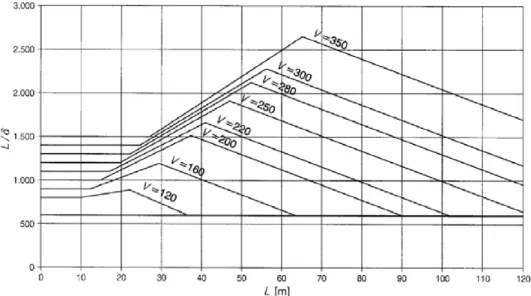
LΦ Determinant length, which represents the length of the influence line for deflection of the element being analysed
LM71 Traffic load model LM71 as defined by EN 1991-2 𝑚 Total number of nodes in the load path
𝑀(𝑡) Time record of the transverse bending moment
𝑀, 𝐶, 𝐾, 𝐹 Mass, Damping, Stiffness and Load related to a specific vibration mode 𝐌, 𝐂, 𝐊, 𝐅 Mass, Damping, Stiffness and Loads matrices of the structure
𝑀𝐴,𝐵,𝐶,𝐷 Bending moment obtained by static analysis (A), moving load analysis (B) and TBI analysis without (C) or with (D) the inclusion of track irregularities
M Carbody translational mass
MC90 Model Code 1990
𝑛 Number of modes considered in the analysis 𝑛 Total number of clusters
𝑛 Number of applied stress cycles
𝑛 Number of neoprene layers
𝑁 Number of permissible load cycles, before fatigue failure 𝑁 Total number of vibration modes
𝑁(𝑡) Time record of the transverse axial force
𝑛0 Natural frequency related to a vertical bending vibration mode 𝑛𝑇 Natural frequency related to a torsional vibration mode
𝑁∗ Total number of vibration modes considered in the analysis
𝑁∗ Number of load cycles at fatigue failure at the trasition between slopes of the S-N curve for reinforcing and prestressing steel
𝑃𝑘 Static load per axle k
𝑝𝑠 Reinforcement percentage in the homogenised section
𝑟 Rail irregularities
𝑟 Residue of the objective function’s terms
S𝑗 Sensitivity coefficients
t Time step
𝑡 Concrete age (in days)
𝑡𝑏𝑎𝑙 Thickness of the ballast layer
𝑡𝑐 Thickness of the reinforced concrete slab 𝑡𝑖 Thickness of each bearing’s neoprene layer
𝐮, 𝐮̇, 𝐮̈ Displacement, velocity and acceleration vectors (nodal coordinates) 𝑢𝑏𝑘 Displacement of the bridge (b) under a contact node, in iteration k 𝑢𝑡𝑘 Displacement of the train (t) at each contact node, in iteration k
𝑣 Train speed
𝑣3 Value that depends on the bearing’s shape 𝑣𝑚𝑎𝑥 Maximum train speed
x𝑗 Initial numerical parameters
𝑥𝑘 Distance between axle k and the first axle of the train
𝑦, 𝑦̇, 𝑦̈ Displacement, velocity and acceleration vectors (modal coordinates)
𝑦𝑑𝑦𝑛 Maximum value of the dynamic response for a specific location of the structure
𝑦𝑛 Record of the modal coordinate for the n-th vibration mode
𝑦𝑠𝑛 Static component of the record of the modal coordinate for the n-th vibration mode
𝑦𝑠𝑡𝑎𝑡 Maximum value of the dynamic response for a specific location of the structure
𝑧 Internal lever arm
z𝑗 Response values for the initial numerical parameters
∏jk Relative modal strain energy representing the portion of total energy mobilised
by vibration mode j considering only the DOFs of cluster k
G
REEK SYMBOLS𝛼 Factor for quantification of classified railway traffic loads
𝛽𝑐𝑐(𝑡0) Coefficient to define the concrete compressive strength at the time 𝑡0 𝛾, 𝛽 Parameters that control stability and precision of Newmark’s method 𝛾𝐹,𝑓𝑎𝑡 Partial factor for cyclic actions
Δ𝜎𝑒𝑞𝑢𝑖𝑣 Damage equivalent stress range
∆𝜎 Stress range
∆𝜎𝑠 Specific stress amplitude
𝜀 Tolerance
𝜂 Ratio between fundamental frequencies of the primary suspension of the train and the bridge
𝜆 Factor related to track maintenance
𝜆 Wavelength
𝜆0 to 𝜆4 Correction factors for calculation of damage equivalent stress ranges 𝜇𝑛𝑒𝑜𝑝 Neoprene-steel friction coefficient
𝜇𝑇𝑒𝑓 Teflon-steel friction coefficient 𝜈𝑏𝑎𝑙 Ballast Poisson’s ratio
𝜈𝑐 Concrete Poisson’s ratio 𝜈𝑛𝑒𝑜𝑝 Neoprene Poisson’s ratio 𝜈𝑟𝑎𝑖𝑙 Steel (rail) Poisson’s ratio 𝜈𝑠 Steel Poisson’s ratio
𝜈𝑠𝑙𝑒𝑒𝑝𝑒𝑟 Concrete (sleeper) Poisson’s ratio 𝜈𝑇𝑒𝑓 Teflon Poisson’s ratio
𝜉 Modal damping ratio
𝜌𝑏𝑎𝑙 Ballast density weight 𝜌𝑐 Concrete density weight 𝜌𝑟𝑎𝑖𝑙 Steel (rail) density weight
𝜌𝑠 Steel density weight
𝜌𝑠𝑙𝑒𝑒𝑝𝑒𝑟 Concrete (sleeper) density weight
σ Standard deviation
𝜎𝑐𝑑,𝑚𝑎𝑥,𝑖 Upper stress in a cycle, to define the fatigue strength of concrete under compression
𝜎𝑐𝑑,𝑚𝑖𝑛,𝑖 Lower stress in a cycle, to define the fatigue strength of concrete under compression
𝜎𝑠(𝑡) Time record of the steel stress
𝜑𝑑𝑦𝑛′ Factor to describe the dynamic enhancement
𝜑′′ Factor to describe the dynamic enhancement due to track defects and vehicle imperfections
𝛷 Dynamic factor
𝚽𝑖 Vector containing the experimental information of the vibration mode i 𝚽𝑗 Vector containing the coordinates of the numerical mode j
𝚽𝑗𝑘 Matrix containing the modal information of numerical modes j, corresponding to the DOFs of cluster k
𝚽𝑗𝑙 Matrix containing the modal information of numerical modes j, corresponding to the DOFs of cluster l
𝛟𝑖𝑒𝑥𝑝, 𝛟𝑖𝑛𝑢𝑚 Vectors containing the experimental and numerical modal information ω𝑗 ngular frequency of numerical mode j
Introduction
1.1
Scope of the thesis
During the last decades railway system has shown a major influence over the economic and social development of our society. In Europe, the railway transport assumes an important role to achieve the 2020 strategy, a strategy towards to the development of a smarter, more sustainable and more competitive economy (European Commission 2008). The introduction of new high-speed lines, or the modernisation of the existing ones, has contributed largely to this growth, reducing journey times, improving the passenger riding comfort and reducing congestion on the overall transport infrastructure network. It has created opportunities for a modal shift from air and road to rail which has brought environmental gains. As consequence, this has also become beneficial for the rail freight since high-speed lines have freed up essential capacity for more freight trains on the classical network, which have been increasingly used in the transport of heavy bulky goods, consumer goods and construction materials, connecting the main ports with the major cities and reducing considerably the number of lorries and congestion on the main roads.
Although road remains the most used mode of transport in Europe, the demand for passenger rail transport grew by 17 % between 2000 and 2012, partially driven by the expansion of the European high-speed railway network (ECORYS 2014). However, rail freight volumes dropped considerably during the period from 2007 to 2009, as a result of the economic
terms of modal share, rail transport supplied 11.0 % of freight and 6.3 % of passenger transport in 2011 [Figure 1.1 b)].
a) b)
Figure 1.1 – Development of passenger/freight transport in the EU: a) passenger/tonnes-kilometres between 2004 and 2012; b) modal split in 2011 (ECORYS 2014)
This development in the railways has been possible due to the construction of a significant number of bridges and viaducts. Taking into account the specific characteristics of the railway traffic, the design of railway bridges must address to some technical constraints, which have led to the adoption of structural solutions with higher stiffness levels when compared to the ones adopted to road bridges. Several and distinct structural solutions have been widely used, depending on the material (steel, reinforced or prestressed concrete and composite steel-concrete solutions) or the deck configuration (slab, I girders or box girders). Generically, the increase in the stiffness levels has been achieved essentially through the main girders, using either I-shaped or U-shaped girders connected by an upper reinforced concrete deck or, alternatively, using cast-in-place box girders.
In Spain, U-shaped prefabricated girders connected by an upper concrete slab were widely employed in the construction of bridge decks with one or more box girders. According to Aparicio (2004), simply supported schemes present good performance for spans between 10 and 30 m and continuous schemes up to 38 m. Two examples are the Martorella viaduct [Figure 1.2 a)], constructed in high-speed line between Madrid and Barcelona, and the Ricla viaduct [Figure 1.2 b)], constructed in the high-speed line between Madrid and Zaragoza.
In Italy, more than 90 % of new railway viaducts included in the high-speed network were made with simply-supported integrally prestressed concrete decks. However, other solutions were adopted as the use of several prestressed U-shaped girders or I-shaped girders connected by an upper slab cast in situ (Evangelista and Vedova 2004).
a) b)
Figure 1.2 – U-shaped girders connected on the top by a reinforced concrete slab, used in high-speed lines: a) Martorella viaduct; b) Ricla viaduct (Aparicio 2004)
Composite solutions have also been employed, essentially composed of two steel plate girders connected on the top by a reinforced concrete slab. An example of this structural solution was applied in the construction of the Haute-Colme viaduct, in France, a remarkable work of TGV Nord taking into account its total development of 1827 m (Figure 1.3).
a) b)
Figure 1.3 – Composite steel-concrete railway viaduct: a) typical cross-section; b) bottom view of the Haute-Colme viaduct (Figueiredo 2007)
Bearing in mind the aforementioned growth in the use of railways, and the evolution expected for a near future, this type of structures is nowadays subjected to high intensity moving loads, where the dynamic effects can reach significant values. Reinforced concrete
(RC) deck slabs in railway bridges and viaducts can be particularly sensitive to these dynamic effects, which increase due to higher train speeds and higher axle loads can lead to excessive bridge vibrations, giving rise to fatigue damage and setting in risk the traffic safety (ERRI D214/RP9 2001, Gabaldón et al. 2004).
Several authors (Schlafli and Bruhwiler 1998, Pimentel et al. 2008, Zanuy et al. 2011) pointed out that these are the bridges’ structural elements most susceptible to the occurrence of fatigue phenomena. A high number of loading cycles can occur, which typically exceeds 10 million and, in some structures, reaches 100 million over the total life of the structure. This is due to the fact that they often present a low thickness and a low reinforcement rate, in order to comply with the standard’s recommendations as far as static behaviour is concerned.
As aforementioned, one of the specificities of this type of structures is related to the use of prestressed concrete or steel plates as main girders in the longitudinal direction, reason why there is generally no cracking related with the stresses in this direction. The fatigue resistance of deck slabs is usually controlled by the fatigue damage of transverse tensile reinforcement and not by the fatigue damage of concrete. In fact, as mentioned by Johansson (2004), in slab plates subjected to significant cyclic bending moments, fatigue of concrete under compression is not observed in experiments, due to the redistribution of concrete stresses within the cross-sections that prevents the fatigue failure of concrete and results in fatigue of the reinforcement.
The evaluation of the fatigue behaviour plays an important role in the design of new structures subjected to cyclic loading. This becomes even more crucial when has been proved that several existing railway bridge decks do not comply with the requirements of actual design codes in terms of fatigue resistance (Bogaert 2009). A carefully assessment of fatigue strength in railway bridge decks should be performed, reason why this thesis aims to contribute to the knowledge about the real performance of these structures, in terms of dynamic behaviour and fatigue resistance, and also to give a contribution in terms of numerical methods for its assessment.
1.2
Main objectives and contributions
The main motivation for the research work presented in this dissertation is the paucity of studies carried out to evaluate the dynamic behaviour and fatigue resistance of reinforced
concrete slabs used in the construction of railway bridges or viaducts. As previously highlighted, the specific loading related to railway traffic leads to important dynamic effects, due to higher train speeds, higher axle loads and the existence of track irregularities or wheel defects, which can lead to excessive bridge vibrations. However, most of the work developed in this field takes into account only the global performance of the structure or lacks experimental evidence. So, bearing in mind that the fatigue phenomenon is strongly dependent on the dynamic behaviour of the structure, the main objectives of this thesis are both the study of the local dynamic behaviour and the fatigue assessment of RC deck slabs, based on numerical and experimental information. For this purpose, two real structures are analysed: the Alverca railway viaduct and the access viaduct to the Alcácer do Sal bridge.
With the final objective of an accurate fatigue analysis, even without using some of the complex methodologies that can be found in the literature, in the present dissertation powerful and accurate numerical tools are used firstly to evaluate the dynamic behaviour of slabs. Advanced three-dimensional numerical models of the bridges and trains are used. A calibration methodology of numerical models is used, taking into account an optimisation method through a genetic algorithm and based on modal information experimentally obtained. Dynamic numerical responses taking into account the interaction between the train and the bridge, either the global responses of the structures or the local responses of the reinforced slabs, are validated through the comparison with the real structural performances measured under railway traffic.
The specific contributions of this thesis are as follows:
an interconnection of the aforementioned numerical tools in order to obtain accurate numerical responses, regarding the dynamic behaviour of the RC deck slabs, in order to perform its fatigue assessment;
the use of a static correction procedure within the train-bridge interaction methodology, which leads to obtain the static contribution of vibration modes of higher frequencies, which are not explicitly considered in the basic modal-superposition method (used to solve the dynamic problem);
the experimental approach for the identification of modal parameters (natural frequencies, mode shapes and damping coefficients), based on ambient vibration tests, specifically related to the local behaviour of the RC deck slabs;
the development of a methodology to identify accurate modal damping coefficients, related to local vibration modes of the RC deck slabs, for vibration levels corresponding to the passage of trains instead of using the values provided by ambient vibration tests;
the evaluation of the effects of distinct track irregularities (different real profiles and space variability), modal damping coefficients and trains’ speed in the dynamic behaviour and fatigue resistance of RC deck slabs of railway bridges.
1.3
Layout of the thesis
The present dissertation is divided into 7 chapters, whose content is briefly summarised in the following paragraphs.
The current Chapter 1 presents the scope of this thesis, describes the motivation for its development and the main contributions to the research field, and outlines the organisation of the document.
Chapter 2 is dedicated to the review of the state of the art concerning the dynamic behaviour of railway bridges. The most typical approaches that can be used to evaluate the numerical evaluation of bridges’ dynamic response are analysed, with particular focus on the train-bridge interaction method. Some of the recommendations defined in the European standards, in order to guarantee both the structural and operational safety of railway bridges in high-speed railway lines, are also presented.
Chapter 3 starts with a brief presentation of the fatigue behaviour of reinforcing steel, concrete and reinforced concrete structures. The methods suggested on European Standards for the fatigue-strength verification are presented, with particular attention to the damage accumulation method, used in the present work.
Given the great importance of the real response of structures, Chapter 4 starts with an overview of some experimental techniques widely used to obtain the dynamic response of bridges, either to identify its modal parameters or to measure its dynamic behaviour under railway traffic. Afterwards, regarding the calibration of finite element numerical models, the steps involved in an iterative method based on an optimisation algorithm are presented, namely, the sensitivity analysis, the vibration modes’ pairing and the optimisation phase.
Chapters 5 and 6 are dedicated to the study of the local dynamic behaviour and fatigue resistance in two real railway bridges, the Alverca railway viaduct and the access viaduct to Alcácer do Sal bridge, respectively. In both chapters, three-dimensional finite element numerical models are developed, calibrated and validated based on experimental tests. Detailed calculations of internal forces are performed through train-bridge interaction numerical analyses. A static correction procedure is also implemented, and validated, in these dynamic analyses to take into account the static contribution of higher-frequency vibration modes. The effects of different track irregularities, modal damping coefficients and trains’ speed on the dynamic behaviour of the upper deck slab are discussed. Finally, based on the results of different train-bridge interaction dynamic analyses, the assessment of the fatigue damage in the transverse reinforcement bars of the upper deck slab is performed.
In Chapter 7 the main conclusions of the present work are summarised as well as some future research topics.
Dynamic behaviour of railway bridges
2.1
Introduction
The railway system and its infrastructures have over the last decades played a key role in the process of economic development of our society. On one hand, the introduction of high-speed trains has contributed largely to this growth, reducing travel time and improving the passenger comfort. On the other hand, freight trains have been increasingly used in the transport of heavy bulky goods, consumer goods and construction materials, connecting the main ports with the major cities, reducing considerably the number of lorries and congestion on the main roads.
This development has been possible due to the construction of a significant number of bridges and viaducts. This type of structures is nowadays subjected to high intensity moving loads, where the dynamic effects can reach significant values. Due to higher train speeds, higher axle loads and the existence of track irregularities or wheel defects, particular attention has been given to these dynamic effects, since they can lead to excessive bridge vibrations and consequently may put in risk the traffic safety. Some research works (ERRI D214/RP9 2001, Gabaldón et al. 2004) have highlighted that the resonance phenomenon, originated by periodic loading associated with the passage of regularly spaced train’s axles groups, may occur in these structures at speeds above 200 km/h. This phenomenon can lead to problems such as the ballast instability, the loss of contact between the wheel and the rail, fatigue damage or affect the passenger comfort. In order to evaluate such effects and evaluate the dynamic behaviour of the
structure, numerical analyses are usually performed. Some representative researches can be cited.
Museros et al. (2004) studied the evolution of the wheel-rail contact forces in high-speed simply supported railway bridges during resonance situations, comparing the theoretical model with a real case scenario. The authors found oscillations in the wheel-rail contact forces during the passage of the axles over the bridge, which become more severe during resonance, especially for the rear wheels rather than the front ones. Xia et al. (2006) also evaluated the resonance effects on a railway bridge subjected to the passage of high-speed trains by means of theoretical methodologies, numerical simulations and experimental tests. According to the authors, the resonance of the train-bridge system is essentially affected by the span, total length of the bridge as well as its vertical and transverse stiffness, and also by the characteristics of the trains, namely, load distribution scheme and natural frequency of the trains.
Regarding the evaluation of the ballast layer instability, Norris (2005) and Zacher and Baeβler (2009) have carried out several experimental tests. In both cases, the authors found that the limit to the maximum vertical acceleration of the deck, imposed by the European Standard EN1990-A2 in order to avoid the ballast instability, is very conservative and have suggested more suitable values. Later on, Baeβler et al. (2012) also evaluated the maximum frequency that should be considered in the dynamic analyses. These authors revealed that, in a way to prevent ballast instability, which is associated with higher frequency vibration modes, it would be advisable to consider the maximum frequency threshold equal to 60 Hz.
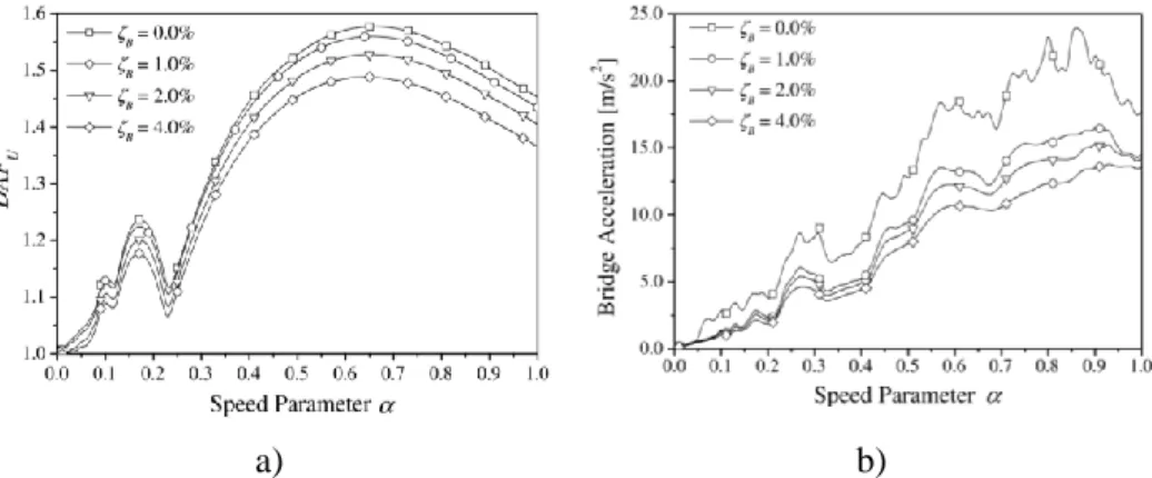
The effects of several parameters on the response’s dynamic amplification of railway bridges, such as the train speed, wheelbase, frequency range and structural damping to be considered in the analyses, were evaluated by Majka and Hartnett (2008). As an example, one can observe in Figure 2.1 the considerable decrease in the vertical acceleration, in the mid-span section of the bridge, to increasing values of the structural damping coefficient, revealing the importance in the correct quantification of this parameter.
a) b)
Figure 2.1 – Influence of damping on the structural response in: a) the dynamic amplification factor (DAF); b) the acceleration of the bridge (Majka and Hartnett 2008)
Other authors, such as Ülker-Kaustell & Karoumi (2012) and Leander & Karoumi (2013), also carried out some studies to understand how structural damping affects the global dynamic behaviour of railway bridges. Leander and Karoumi (2013) carried out a numerical study considering modal damping coefficients between 0 % and 3 % (keeping a constant value for all of the 50 vibration modes considered in analyses), showing that lower damping coefficients give rise to considerably higher fatigue damages, especially in the case of simply supported structures. They also showed that damping strongly affects the bridge response after the train leaves the structure.
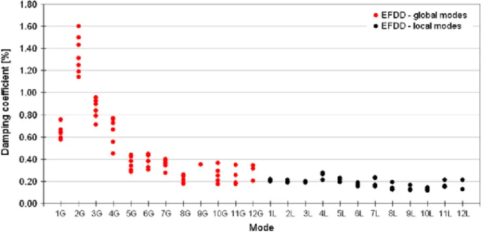
Ribeiro et al. (2012), resorting to ambient vibration tests carried out in a bowstring-arch railway bridge, identified the modal damping coefficients of several global and local vibration modes of the structure (Figure 2.2). These authors showed that the experimentally identified damping coefficients can be very different from the value of 0.5 %, which is proposed by EN 1991-2 (2003) for the design of bridges with steel-concrete deck and spans greater than 20 m. The authors also presented values for damping coefficients of the local vibration modes of the hangers and diagonals of the arch, which have a low dispersion and are generally located between 0.10 % and 0.30 %.
Figure 2.2 – Damping coefficients estimates for global and local vibration modes for different experimental setups (Ribeiro et al. 2012)
Track irregularities are an important source of excitation that may affect the ride comfort, the train response and safety and also the bridge dynamic response. There are two different ways to define the track irregularities to be used in the numerical analyses: using experimentally measured values or through random generation using power spectral density (PSD) functions. Concerning the latter approach, Rocha et al. (2014), performing dynamic analysis considering irregularities wavelengths between 3 m and 25 m, have shown significant differences in the global behaviour of a railway bridge, in terms of vertical accelerations in different cross-sections, by comparing the results for a perfect track and a track with irregularities.
Cantero et al. (2016) have also discussed the effect of different wavelength ranges (3-25 m, 25-70 m and 70-150 m) on global bridge deck acceleration, for different train speeds. These authors showed that the major contribution to the increase of the dynamic response (with respect to the response for a smooth rail without irregularities) comes from the lower wavelength range (3-25 m), as can be seen in Figure 2.3. Within the scope of the Rivas research project (2013), where the importance of experimentally measured track irregularities for ground-borne vibrations was analysed, the relevance of irregularities with smaller wavelength (in the interval 0.5 m to 3 m) has also been demonstrated.
Figure 2.3 – Effect of track irregularity wavelengths in the vertical acceleration of a bridge (Cantero et al. 2016)
Herwig & Bruhwiler (2011), found that track irregularities may be one of the main causes for dynamic effects for fatigue relevant bridge elements, leading to amplifications of the bridge dynamic response and that the wheel-force variation leads to an almost immediate bridge response. Based on measurements and simulations from a prestressed concrete bridge girder, the authors obtained dynamic amplification factors that vary with varying train velocity. A maximum occurs at the resonance speed for maximum vehicle excitation due to track irregularities. The authors pointed out that high contact force amplitude leads to high action effect amplitudes but the maximum dynamic wheel forces do however not necessarily occur always at the location leading to maximum action effect (such as the bending moment).
Sousa (2012) developed a numerical methodology to evaluate the fatigue behaviour of cracked reinforced concrete elements subjected to cyclic loading, validating the results through laboratory tests and applying it in a railway bridge case-study. The author verified that the existence of cracks can be considered in linear dynamic analysis through a reduction of the bending stiffness, and that this reduction leads to an increase in the vertical displacements of the structure, to a decrease in the frequencies of vibration and to a decrease of the resonant speeds during the passage of high-speed trains [see Figure 2.4 related to the latter effect].
a)
b)
Figure 2.4 – Maximum vertical acceleration in the mid-span section of the bridge as function of the train speed: a) without the influence of cracks; b) with the influence of cracks (adapted from Sousa (2012))
Dynamic analysis is thus of particular importance, essentially due to several parameters that should be taken into account in order to obtain accurate results. In this Chapter, the most important aspects regarding the dynamic behaviour of railway bridges are presented and discussed. The most typical approaches that can be considered to perform the numerical evaluation of the dynamic response are analysed, with particular focus on the train-bridge interaction method which allows obtaining the most realistic results. Finally, some of the recommendations defined in the European standards, in order to guarantee both the structural and operational safety of railway bridges in high-speed railway lines, are presented.
2.2
Numerical evaluation of the dynamic behaviour
There are several methodologies that can be used to analyse the bridge dynamic response regarding the passage of trains, namely, numerical, simplified, analytical or empirical methods. A detailed description of different methods can be found in Barbero (2001). The numerical
analysis methodologies are nowadays among the most used techniques to verify the dynamic behaviour of structures, and for this reason they are the only ones detailed in the present section. Two main methods for studying the dynamic behaviour of a railway structure are discussed: moving loads (section 2.2.1) and train-bridge interaction (section 2.2.2). These methods vary in complexity, computational cost and accuracy as will be discussed in the following subsections.
2.2.1 Moving loads method
The moving loads method do not consider the interaction between bridge and trains since the latter are characterised by a set of moving loads spaced apart according to trains’ geometry. Each load is defined by a value related to the static load of each axle, as shown in Figure 2.5.
Figure 2.5 – Schematic representation of the moving loads method
The dynamic response of the structure can be calculated, in each time step t, by solving the following dynamic equation of motion:
𝐌𝐮̈(𝑡) + 𝐂𝐮̇(𝑡) + 𝐊𝐮(𝑡) = 𝐅(𝑡) (2.1)
where M, C and K are the mass, damping and stiffness matrices of the structure, respectively and F is the vector of external loads applied to the structure (generic external loads and time-dependent moving loads of the train). Equation 2.1 can be solved using direct integration techniques, such as the Newmark method (Clough and Penzien 1993), the Wilson-θ method and the Hilber-Hughes-Taylor (HHT) method (Cruz 1994, Calçada 1995, Neves 2008), or using the modal superposition method (Chopra 1995, Clough and Penzien 1993).
This method can be used with sufficient accuracy in cases where the train-bridge interaction does not significantly influence the dynamic response of the structure, such as where the train’s mass is considerably lower when compared to the bridge’s mass (Martínez-Rodrigo 2009, Goicolea and Gabaldon 2012). Short to medium span bridges are not within these cases. They
should be carefully analysed since the moving loads method may sometimes underestimate the real bridge’s deck response.
It thus becomes a methodology of greater simplicity to apply, with reduced effort and computational times, but limited to the study of the dynamic response of the structure. Furthermore, this method does not allow considering the effect of track irregularities. Examples of the application of this method can be found in the works of Albuquerque et al. (2010) and Rocha et al. (2012).
2.2.2 Train-bridge interaction method
2.2.2.1 Overview
The methodology based on the consideration of the train-bridge interaction (TBI) is a method of greater complexity in terms of computational implementation but more realistic regarding to the results obtained, since it takes into account both the dynamic characteristics of the bridge and the train, by considering the effects associated with the interaction forces that develop with the passage of the train over the structure. Due to the explicit modelling of the bridge, track and train, this methodology allows not only an accurate assessment of the dynamic behaviour of railway bridges but also the evaluation of the ride comfort, the wheel-rail stability or the effects of track irregularities.
In order to evaluate the TBI effects, ERRI's D214 (2001) expert committee conducted a number of analyses considering distinct bridges and two types of trains, the conventional ICE2 and the articulated EUROSTAR trains. Concerning large-span bridges, the commission found that the response of the structure is very similar whether or not the TBI is considered. The main differences were observed in small-span bridges but only in the proximity of resonance speeds, where considering the interaction leads to lower displacements and accelerations. This commission also defined an additional value for structural damping in order to take into account the interaction effects in analyses according to the moving loads method, thus allowing for simpler analyses without explicit consideration of this phenomenon.
Museros et al. (2002) also compared the dynamic behaviour of several simply supported bridges using both the moving loads and the TBI methods, concluding that the interaction effects lead to a significant reduction (around 25%) of the maximum dynamic response.
The dynamic problem, considering now the interaction between the bridge and the train, can be solved considering the two systems, bridge and train, in coupled or uncoupled sets of equations. The uncoupled consideration of the dynamic equilibrium equations of the two systems requires less computational effort than the coupled resolution, since in the latter case the matrices are generated together and subsequently solved together as well, requiring to be constantly updated at each time step. Examples of application of the coupled approach can be found in Yang et al. (2004) and Neves et al. (2012).
In the case of uncoupled dynamic equilibrium equations, the compatibilisation of the two systems, bridge and train, can be done based on iterative methods (Cruz 1994, Calçada 1995, Lei and Noda 2002) or through direct methods, as developed by Neves et al. (2012). Dynamic equilibrium equations can be solved based on direct integration methods, such as the Newmark or Wilson-θ methods, or based on the modal-superposition method.
In the iterative methods, the two systems are solved simultaneously over time, resorting to an iterative process in each time step in order to obtain the compatibility of the two structural systems, in terms of the dynamic component of the interaction force and the displacement in the contact nodes. The dynamic equilibrium equations of both systems can be written separately as follows (Calçada 1995):
[ 𝐌0𝑏 𝐌0 𝑡 ] [ 𝐮̈𝑏(𝑡) 𝐮̈𝑡(𝑡) ] + [ 𝐂𝑏 0 0 𝐂𝑡 ] [ 𝐮̇𝑏(𝑡) 𝐮̇𝑡(𝑡) ] + [ 𝐊𝑏 0 0 𝐊𝑡 ] [ 𝐮𝑏(𝑡) 𝐮𝑡(𝑡) ] = [ 𝐅𝑏(𝑡) 𝐅𝑡(𝑡) ] (2.2)
where M, C and K are the mass, damping and stiffness matrices, respectively. F is the load vector and 𝐮̈, 𝐮̇, and 𝐮 are the vectors of accelerations, velocities, and displacements, respectively. The subscripts "b" and "t" stand for bridge and train, respectively.
Each time step (∆𝑡) involves the following operations:
1. In the iteration k, the moving loads in correspondence to the axles of the train are applied in the structure. Each moving 𝐹𝑏𝑘(𝑡) load is given by:
𝐹𝑏𝑘(𝑡) = 𝐹
𝑠𝑡𝑎𝑡+ 𝐹𝑑𝑦𝑛𝑘−1(𝑡) (2.3)
where 𝐹𝑠𝑡𝑎𝑡 is the static load, constant over time, and 𝐹𝑑𝑦𝑛𝑘−1(𝑡) is the dynamic component of the interaction force calculated in the previous iteration (equal to 𝐹𝑑𝑦𝑛(𝑡 − ∆𝑡) in the first iteration). By solving the system of equations related to the bridge (see Equation 2.2), the nodal displacements are computed and consequently
2. At the same time, in each contact node of the train a displacement (𝑢𝑡𝑘(𝑡)), corresponding to the sum between the displacement 𝑢𝑏𝑘(𝑡) and the track irregularity 𝑟(𝑡) that may exist between the wheel and the rail, is imposed. By solving the system of equations related to the train (see Equation 2.2), the reaction forces 𝐹𝑡𝑘(𝑡) at the contact nodes are computed. These forces are the dynamic components of the interaction forces 𝐹𝑑𝑦𝑛𝑘 (𝑡) to be applied to the structure in the following iteration. 3. At the end of each iteration a convergence criterion is used, which takes into account
the dynamic components of the interaction forces of the current and previous iterations. For each moving load, the convergence is verified based on the following equation:
‖𝐹𝑑𝑦𝑛𝑘 (𝑡) − 𝐹𝑑𝑦𝑛𝑘−1(𝑡)‖
‖𝐹𝑑𝑦𝑛𝑘−1(𝑡)‖ ≤ 𝜀 (2.4)
where 𝜀 is a specified tolerance. If the desired degree of convergence is achieved, the procedure may advance to the next time step (𝑡 + ∆𝑡), otherwise the iterative process continues to the next iteration. The process starts by assuming that the dynamic component of the interaction force at the initial instant of time, 𝐹𝑑𝑦𝑛(𝑡 = 0), are zero.
The iterative procedure described above is generically schematized in Table 2.1.
Table 2.1 – Iterative method to solve the TBI dynamic problem (Ribeiro 2012)
Bridge Train Scheme Load 𝐹𝑏𝑘(𝑡) = 𝐹𝑠𝑡𝑎𝑡+ 𝐹𝑑𝑦𝑛𝑘−1(𝑡) 𝑢𝑡𝑘(𝑡) = 𝑢𝑏𝑘(𝑡) + 𝑟(𝑡) Result 𝑢𝑏𝑘(𝑡) 𝐹𝑑𝑦𝑛𝑘 (𝑡) = 𝐹𝑡𝑘(𝑡) Convergence criterion ‖𝐹𝑑𝑦𝑛𝑘 (𝑡) − 𝐹 𝑑𝑦𝑛𝑘−1(𝑡)‖ ‖𝐹𝑑𝑦𝑛𝑘−1(𝑡)‖ If ≤ 𝜀 If > 𝜀 k 1 t t

![Figure 2.11 – Schematic representation of complete train: a) front view; b) elevation view; c) plan view [adapted from Xia and Zhang (2005)]](https://thumb-eu.123doks.com/thumbv2/123dok_br/15850607.1085534/53.892.241.690.749.1052/figure-schematic-representation-complete-train-elevation-adapted-zhang.webp)