UNIVERSIDADE DA BEIRA INTERIOR Engenharia
Analysis of Web Protocols Evolution on Internet
Traffic
Karikari Abina Mary
Dissertação para obtenção do Grau de Mestre em
Engenharia Informática
(2º ciclo de estudos))
Orientador: Prof. Nuno M. Garcia
Acknowledgements
First and foremost, I want to express my sincere gratitude to the Almighty God, for his protection, strength and support. Him alone has been the brain behind my success during the period of this study.
I am greatly indebted to my supervisor Professor NUNO. M. GARCIA for his advice, guidance, corrections and useful suggestion during the various stages of this research work. His scholarly criticism and interest in this research has been very rewarding, his promptness and sense of duty during my consultation with him has been highly commendable and which has made great impact in my life. My profound gratitude goes to him.
My special appreciation goes to Mr Oluwafemi Olawale, Mr William Okorukwu Okey, Mr Diallo Ousmane and all my colleage in ALLAB (Assistance Living and Telecommunication Laboratory) for their assistance and support in one way or the other towards the success of this research work. My profound gratitude also goes to my Pastor Mrs Funmi Olanrewaju and her husband Mr Tola Olanrewaju for their prayer and word of encouragement towards the success of this research work.
My profound gratitude also goes to my beloved parent Mr Kingsley Karikari and Mrs Comfort Karikari, Mr Nosa Osasere and my beloved uncles Mr Clement Conno, Mr Kingsley Oridomo for their prayer, moral and financial support towards the success of this project.
This acknowledgement would not be complete without my appreciation to my lovely daughters Blessing Osasere and Joy Osasere for their understanding and cooperation throughout the period of this course.
Resumo
Esta pesquisa foca-se na análise de dez anos de tráfego de Internet, a partir de 2004 até 2013, capturado e medido pelo Mawi Lab numa ligação de fibra óptica entre o Japão e os Estados Unidos da América. O tráfego recolhido foi analisado para cada um dos dias nesse período, e também conjuntamente nesse período. As questões de pesquisa iniciais incluíram testar a hipótese de ser observável no tráfego gerado, a alteração das aplicações em uso na Internet e a alteração dos padrões de uso da Internet. Vários protocolos foram analisados exaustivamente, incluindo HTTP, HTTPS, TCP, UDP, IPv4, IPv6, SMTP e DNS. O efeito da transição do IPv4 para o IPv6 também foi analisado. As conclusões foram tiradas, as questões de pesquisa foram respondidas e a hipótese de pesquisa foi confirmada.
Palavras-chave
Tráfego da Internet, medição de tráfego, análise de tráfego, transição do IPv4 para o IPv6, segurança na Internet, histórico de tráfego, uso da Internet, evolução da Internet.
Abstract
This research focus on the analysis of ten years of Internet traffic, from 2004 until 2013, captured and measured by Mawi Lab at a link connecting Japan to the United States of America. The collected traffic was analysed for each of the days in that period, and conjointly in that timeframe. Initial research questions included the test of the hypothesis of weather the change in Internet applications and Internet usage patterns were observable in the generated traffic or not. Several protocols were thoroughly analysed, including HTTP, HTTPS, TCP, UDP, IPv4, IPv6, SMTP, DNS. The effect of the transition from IPv4 to IPv6 was also analysed. Conclusions were drawn and the research questions were answered and the research hypothesis was confirmed.
Keywords
Internet traffic, traffic measurement, traffic analysis, IPv4 transition to IPv6, Internet security, traffic history, Internet usage, Internet evolution.
Contents
1 Introduction ... 1 1.1 Background ... 1 1.2 Objective ... 2 1.3 Research Questions ... 2 1.4 Hypothesis ... 3 1.5 Thesis organization ... 32 State of the Art ... 5
2.1 The Evolution of TCP/IP and the Internet ... 5
2.1.1 The Open System Interconnected Model (OSI) ... 7
2.1.1.1 Physical Layer ... 8
2.1.1.2 Data Link Layer ... 8
2.1.1.3 Network Layer ... 9
2.1.2 Internet Protocol ... 9
2.1.2.1 Internet Protocol Version 4 (IPv4) ... 10
2.1.2.2 Internet Protocol Version 6 (IPv6) ... 10
2.1.2.3 Comparison of IPv4 and IPv6 features ... 11
2.1.3 Transport Layer ... 14
2.1.3.1 Transmission Control Protocol (TCP) ... 14
2.1.3.2 User Datagram Protocol (UDP) ... 16
2.1.3.3 UDP and TCP Performance ... 17
2.1.4 Session Layer ... 19 2.1.4.1 Presentation Layer ... 19 2.1.4.2 Application Layer ... 19 2.1.4.3 HTTP Protocol ... 20 2.1.4.4 HTTPS Protocol ... 20 2.1.5 Network security ... 21
2.1.5.1 Importance of Network Security ... 22
2.1.5.2 Network Security Threats ... 23
2.1.5.3 External Threats ... 23 2.1.5.4 Internal Threats... 23 2.2 Network Traffic ... 24 2.2.1 Network Monitoring ... 24 2.2.2 Traffic Flow ... 25 2.2.3 Traffic Profiling ... 26 2.2.4 Traffic Analysis ... 26
2.3 Internet traffic measurement ... 27
2.3.1 The Evolution of Internet Traffic Measurement ... 27
2.4 Internet Applications ... 32
2.4.1 MSN ... 33
2.4.2 SKYPE ... 33
2.4.3 Facebook ... 34
2.4.4 Web browsing and Web based email access ... 36
2.5 Network Traffic Growth ... 36
2.6 The growth in Social network Traffic ... 38
3 Data Trace Selection ... 39
3.1 The WIDE Project and MAWI ... 39
3.2 MAWILab ... 39
3.3 Description of MAWI dataset and collection point ... 40
3.4 Limitations on the recorded data ... 41
3.5 Reason for choosing this collection point ... 41
3.6 The scope of the selected data trace ... 42
4 Result for Data Trace Analysis ... 43
4.1 Analysis of our Results ... 43
4.2 Conclusion ... 50
5 Conclusion ... 53
5.1 Summary and contribution ... 53
List of Figures
Figure 2.1 - The OSI Reference Model. ... 8
Figure 2.2 - Internet Protocol version 4 header. ... 11
Figure 2.3 - Internet Protocol version 6 header. ... 13
Figure 2.4 - Transmission Control Protocol Header. ... 15
Figure 2.5 - User Datagram Protocol Header. ... 16
Figure 2.6 - Twenty most popular social network website May 2010. ... 38
Figure 2.7 - Expansion in the demand for video 2008-2014. ... 38
Figure 4.1 - IPv4 number of packets. ... 44
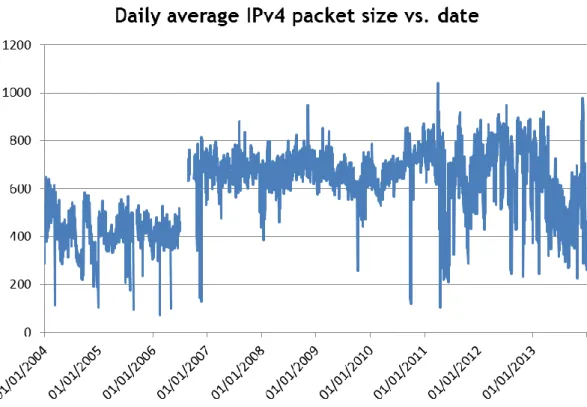
Figure 4.2 - IPv4 average packet size. ... 44
Figure 4.3 - An overview IPv6 number of packets... 45
Figure 4.4 - IPv6 average packet size. ... 46
Figure 4.5 - IPv4 and IPv6 packets. ... 46
Figure 4.6 - TCP vs. UDP on IPv4 protocol. ... 47
Figure 4.7 - other% TCP and other% UDP on IPv4 protocol. ... 48
Figure 4.8 - HTTP vs. HTTPS on IPv4 protocol. ... 48
Figure 4.9 - Percentage of SMTP and SSH on IPv4 protocol. ... 49
Figure 4.10 - DNS in IPv4 protocol. ... 50
List of Tables
Table 2.1 - IPv4 Address Range ... 10 Table 2.2 - UDP and TCP comparative features. ... 18
Acronyms
TCP Transmission Control Protocol
UDP User Datagram Protocol FTP File Transfer Protocol
HTTP Hypertext Transfer Protocol
HTTPS Hypertext Transfer Protocol Secure IP Internet Protocol
DNS Domain Name System
SMTP Simple Mail Transfer Protocol ISP Internet Service Provider
MSN Microsoft Network
OSI Open System Interconnected Model
NCP Network Control Protocol
ARPA Advanced Research Projects Agency IPv4 Internet protocol version 4
IPv6 Internet protocol version 6
POP3 Post Office Protocol ACK Acknowledgement
NACK Negative acknowledgement SSL Secure Sockets Layer
SSH Secure shell
IMAP Internet Message Access Protocol SNMP Simple Network Management Protocol TFTP Trivial File Transfer Protocol
NFS Network File System
Chapter 1
1Introduction
1.1 Background
Over the past decades, there have been several technological applications that leverage its performance on the Internet. However the drastic increase in research and technological advancement and application development in recent time has popularized the term Internet. The Internet which refers to the global information system that is logically linked together by a globally unique address space based on the Internet Protocol (IP). Its subsequent extensions which is capable of supporting communications using the Transmission Control Protocol, User Datagram Protocol (TCP|UDP) suite and other IP-compatible protocols; and also provides, uses or makes accessible, either publicly or privately, high level services.
Traditionally, UDP which is a much simpler protocol when compared to TCP, because it doesn't require connection setup delays, flow control, or retransmission, and has been used as a transport layer protocol for real-time applications in recent time. Currently, more than 80 percent of the Internet's bandwidth [1] is consumed by TCP-based applications, such as the Hypertext Transfer Protocol (HTTP) and Hypertext Transfer Protocol Secure (HTTPS). Under the TCP flow control, this uses a sliding window flow mechanism. Network traffic is recognized by detection of packet loss. However, when this occurs, the packet is retransmitted. It is still an accepted assumption that Internet traffic is dominated by TCP [2,3].
However, the rise of new streaming multimedia applications [4] such as Microsoft Network (MSN), Skype, Facebook, YouTube, etc. and new P2P protocols that try to avoid traffic shaping techniques (such as RST packet injection) will increase the use of UDP as a transport protocol in future. This substantial increase in UDP usage has raises serious concerns about fairness and stability in the Internet because; currently UDP lacks functionality to adapt to network traffic congestion.
The tremendous increase in the use of these protocols in several applications and the need to meet user needs has necessitated research on Network traffic analysis. Network traffic analysis is a process of capturing network traffic and inspecting it closely to determine what is happening in the network [5]. It is also known by several other names: network analysis, protocol analysis, and packet sniffing and packet analysis to name a few.
Network traffic analysis which is a scientific approach that involves collection and gathering of network traffic data over a period of years, processing, analyzing and interpreting them into a useful information for effective and efficient decision making and tries to highlight the
use and performance of these protocols over a period of time and how they can be improved to meet future use.
This desire to conceptualize network traffic in a prevailing communication network has helped to tackle vast range of problems, including security, attacks and monitoring general health of the network. This project is aimed at evaluating the Analysis of web protocols evolution on Internet traffic.
This research focuses on traffic statistics of the traces that have already been collected every day, for 15 minutes, starting from 2004 January -2013 December. The traffic traces that were utilized in this research was obtained from the online traffic data repository maintained by the Measurement and Analysis on the Wide Internet (MAWI) working group of the WIDE Project and from TMA portal- European research portal on traffic monitoring at www.tma-portal.eu [6].
The longitudinal study on the analysis of web protocols on Internet traffic were investigated at (packet connection level) and its application usages. The research examined and analyzed the Internet traffic over these periods (2004-2013). Also an attempt was made to highlight the trend on Internet applications on Social Network such as Microsoft Network (MSN), Skype and Facebook with the view to analyze their trend on Internet Network Traffic and security issues within the study period.
1.2 Objective
The main aim of this research is to evaluate the changes in Internet Protocol (IP) traffic, and to analyze and visualize the network traffic data at packet connection levels. We try to address various concerns related to the percentage of TCP/UDP traffic, monitor the relevance of the web protocols traffic over the Wide Area Network (WAN) and the Internet. However, an attempt was made on the history, traffic growth and usage of Internet Applications such as Skype, Facebook and MSN.
The achievements of these aims were realized by the following objectives:
(I) analyzing the previously recorded TCP and UDP connection traffic, such as the amount of traffic being transmitted from or received by the host machine, based on different applications.
(II) Examining the details of the data transmission including the size of messages transmitted or received during a given period of time, the source IP address, the destination IP address , the source and destination port number, the type of protocol that have been used.
(III) Evaluating the traffic growth and usage of the Internet Applications.
1.3 Research Questions
Given the current changes in technology and increasing popularity on the numerous online services and applications such as VoIP, VIDEO, and WEB that obtain its performance mostly on
TCP and UDP protocols, how has this change affect the statistics for Network Traffic on the Internet from 2004 -2013?
The following research questions were established so as to provide concrete objectives for the thesis.
(I) what is the evolution of the ratios of use for the different transport protocols over the studied 10 years? Here we addressed various concerns related to the percentage of TCP|UDP traffic, HTTP traffic, IPv4 |IPv6 traffic and their statistics.
(II) What is the effect of these protocols on the Internet Traffic for this period (2004 - 2013)? (III) What is the evolution on the amount of traffic being transmitted from or received by the hosts in this link? Here we obtained previously recorded flows of IP traffic on the Internet for a particular link, evaluate and analyzed the records of the link traffic, i.e. The amount of traffic being transmitted from or receive by the hosts.
1.4 Hypothesis
The change in the Internet application ecosystem in the last 10 years is perceivable through the analysis of the Internet traffic at a random yet ergodic collection point.
1.5 Thesis organization
This thesis is organized in five chapters.
Chapter 1 introduces the scope of this work; define the object, research questions and the hypothesis, the remaining chapters are organized as follows:
Chapter 2 discussed the State of the Art, it also covers the evolution TCP/IP and the Internet, including a description on the Open System Interconnected Model (OSI) layers and details of headers for several important protocols, network traffic, Internet traffic Measurement, the evolution of Internet traffic and COST Action IC0703.
Chapter 3 describes our data trace selection point and the methodology involved in analyzing the traffic data. It also discusses about the approach utilize for analyzing the traffic data, Limitation on the recorded data and the information collected from the WIDE project and MAWI.
Chapter 4 presents the results for our data trace analysis for each protocol that we use for these research and analyze our results at different levels of granularity.
Chapter 5 summarizes the conclusion, followed by the future work for further study of our work presented in this thesis.
Chapter 2
2
State of the Art
Before discussing the evaluation on the usage of different web protocols on Network Traffic, it is useful to talk about the evolution of TCP|UDP/IP and Internet Applications on the Network Traffic. This chapter is divided into six sections, each relating to a important aspect of the research. The first section explains the evolution of TCP/IP and the Internet, including a description on the Open System Interconnected Model (OSI) layers and the details of the headers for several important protocols. Section two discusses the network Traffic including network monitoring, Traffic flow, Traffic profiling and Traffic analysis. Section three focuses on Internet Traffic Measurement, discussing the evolution of Internet Traffic and COST Action IC0703. As to allow us to make comparisons and understand the nature of the collected network Traffic, section four discusses some of the most used network applications for the studied period. This includes MSN, Skype and Facebook. Section five shows recent trends on network traffic growth, including Web browsing and Web based email. Finally section six presents data on the expected growth of social network traffic.
These sections will allow us to make a thorough analysis on the collected data trace.
2.1 The Evolution of TCP/IP and the Internet
Today the Internet is known as a network of networks that is basically changing social, political, and economic structures, and in many ways obviating geographic boundaries. This prospective is merely the recognition of predictions that go back nearly forty years ago. In a series of memos dating back to August 1962, J.C.R. Licklider of MIT discussed his "Galactic Network" and how social interactions could be enabled through Networking.
TCP/IP is a standard suite of protocols that is designed for huge networks consisting of network segments that are linked by routers. It is the protocol that is used on the Internet, which comprises of thousands of Networks worldwide that connect research facilities, universities, libraries, government agencies, private companies, and individuals [7]. TCP/IP is a set of network standards that specify the details of how computers communicate, as well as a set of conventions for interconnecting Networks and routing traffic. The Internet certainly provides such a national and global infrastructure and, in fact, interplanetary Internet communication has already been seriously discussed. TCP/IP was initially designed to meet the data communication needs of the U.S. Department of Defence (DOD).
In the late 1960s the Advanced Research Projects Agency (ARPA, now called DARPA) of the U.S. Department of Defence began a partnership with U.S. Universities and the corporate research community to design open, standard protocols and build multi-vendor networks.
Together, the participants planned The Advanced Research Projects Agency Network (ARPANET), this was the first packet switching Network.
The first experiment for the four-node version of ARPANET went into operation in 1969. These four nodes were connected together at three different sites via 56 Kbit/s circuits, using the Network Control Protocol (NCP). The experiment was a success, and the trial Network finally evolved into a useful operational Network, the "ARPA Internet".
In the year 1974, Vinton G. and Robert E. proposed in a paper the design for a new set of core protocols, for the ARPANET. The official name for the set of protocols was called TCP/IP Internet Protocol Suite, which is generally referred to as TCP/IP, which is taken from the names of the Network layer protocol (IP) and one of the transport layer protocols (TCP). The Institute of Information Sciences at University of Southern California presented a reference document in January 1980 [8] describing the values of the Internet Protocol, designed to be used in an environment of computer communication networks positioned to packet switched systems interconnected between them.
In 1985 ARPANET was faced a problem of congestion and the National Science Foundation’s decide to developed NSFNET to support the prior net which was finally closed in 1989. The NSFNET was built on several regional networks and peer networks such as NASA Science Network. There was a network architecture connecting campuses and research organizations connected also to super computer facilities in 1986. Due to increase in speed of transmissions over the past years, the backbone was moved to a private company in 1991, this innovation make them to start charging for connection for their services, and companies like IBM developed ANSNET in parallel which was now aimed to enrich these companies.
Below is the Summary of TCP/IP milestones:
The history of TCP/IP can be traced back to research conducted by the United States Department of Defence (DOD) Advanced Research Projects Agency (DARPA) in the late 1960s and early 1970s [7].
The following list highlights some important TCP/IP milestones:
In 1970, ARPANET hosts started to use Network Control Protocol (NCP), a preliminary form of what would become the Transmission Control Protocol (TCP).
In 1972, the Telnet protocol was introduced. Telnet is used for terminal emulation to connect dissimilar systems. In the early 1970s, these systems were different types of mainframe computers.
In 1973, the File Transfer Protocol (FTP) was introduced. FTP is used to exchange files between dissimilar systems.
In 1974, the Transmission Control Protocol (TCP) was specified in detail. TCP replaced NCP and provided enhanced reliable communication services.
In 1981, the Internet Protocol (IP) (also known as IP version 4 [IPv4]) was specified in detail. IP provides addressing and routing functions for end-to-end delivery.
In 1982, the Defense Communications Agency (DCA) and ARPA established the Transmission Control Protocol (TCP) and Internet Protocol (IP) as the TCP/IP protocol suite.
In 1983, ARPANET change from the name NCP to TCP/IP.
In 1984, the Domain Name System (DNS) was introduced. DNS resolves domain names (such as www.example.com) to IP addresses (such as 192.168.5.18).
In 1995, Internet service providers (ISPs) began to offer Internet access to businesses and individuals.
In 1996, the Hypertext Transfer Protocol (HTTP) was introduced. The World Wide Web uses HTTP.
In 1996, the first set of IP version 6 (IPv6) standards were published.
2.1.1 The Open System Interconnected Model (OSI)
In 1984, the International Standard Organization (ISO) designed a stand for the communication framework for heterogeneous systems in networks, this system is called Open System Interconnection Model (OSI). The OSI reference model provides a framework to break down complex inter-networks into such components that can be more easily understood and utilized.
The purpose of the OSI is to have an easy communication with other computer anywhere in the world, as long as they follow the OSI standard [9].
This OSI reference model is divided into seven levels, and each of these levels in OSI Model has its own working functionality; these levels are remote but on the other hand cascaded to each other and have communication functionality in a proper flow between them. With reference to above standard communication framework, this set of layers known as OSI layers and their functionalities are presented as shown in figure 1 below.
OSI Model
Data unit Layer Function
Host layers
Data
Application Network process to application
Presentation Data representation, encryption and decryption Session Interhost communication
segment Transport End -end connections and reliability, Flow control
Media layers
packet Network Path determination and logical addressing frame Data link Physical addressing
Bit Physical Media , signal and binary transmission Figure 2.1 - The OSI Reference Model.
The functionality of each layer (or group of layers) is described in a bit more detail below.
2.1.1.1
Physical Layer
The first layer of a network is the Physical layer, the Physical layer is exactly what its name implies: the physical infrastructure of a network.
This includes the cabling or other transmission medium and the network interface hardware placed inside of computers and other devices which enable them to connect to the transmission medium. The purpose of the physical layer is to take binary information from higher layers, translate it into transmission signal or frequency, transmit the information across the transmission medium, receive this information at the destination, and finally translate it back into binary before passing it up to the higher layers.
2.1.1.2
Data Link Layer
In OSI Reference Model the Data Link Layer is the second layer, it is the layer that is responsible for control methods which provides proper format of data and it can access data flow errors in physical layer. The data format in data link layer is in the form of frames, therefore we say that the data link layer is responsible for defining data formats to include the entity by which information is transported. Error control procedures and other link control procedures may occur in physical layer [10]. Like cyclic redundancy check (CRC); the error checking mechanism that run at the time of transmission of a frame from source side. The same mechanism will run at the destination side if they found any difference after comparison then receiver makes a request to source to send that frame again. The data link layer is further subdivided into two layers, Logical link Control (LLC) and Media Access
Control. The logical link control is responsible for flow control and error detection in data. Whereas media access control is responsible for controlling the traffic congestion and physical address reorganization.
2.1.1.3
Network Layer
The third layer in OSI Reference Model is the Network Layer, this layer is responsible to make a logical connection between source and destination. The data at this layer is in the form of packets. The network layer protocols provide the following services which is the connection mode and IP Addressing.
Connection mode: The network layer has two types of connection between source and destination, first one is known as connectionless communication which does not provide connection acknowledgement. The example of connectionless communication is Internet Protocol (IP). The second type of connection is connection-oriented which provides connection acknowledgement. TCP is an example of this connection.
IP Addressing: In computer networks every node has its own unique ID. By this unique ID sender and receiver always make right connection. This is because of the functionality of network layer protocol, which has source address and destination address in their header fields. So there is less chance of packet loss, traffic congestion and broadcasting.
2.1.2
Internet Protocol
The IP is in the third network layer of the OSI model that contains addressing information and some control information that enables packets to be routed. IPv4 is documented in RFC [11] as the primary network-layer protocol in the Internet protocol suite alongside with TCP. IP represent the heart of the Internet protocols because it provides a connectionless best- effort delivery of datagram's through an Internetwork service, which means (No logical connection between the user and the network is established prior to data transmission).
The data units are transmitted as independent units. "and providing fragmentation and reassembly of datagram's to support data links with different maximum-transmission unit (MTU) sizes [12]. Because of this feature, IP is robust, however unreliable. An IP packet can be lost, duplicated or arrive out of order. IP was not designed to deal with these problems. It does not provide error recovery or flow control. These functions can be provided by an upper layer (transport layer) connection-oriented protocol, e.g. TCP. Currently there are two versions of the IP protocol, IP version 4 (IPv4), and IP version 6 (IPv6).
2.1.2.1
Internet Protocol Version 4 (IPv4)
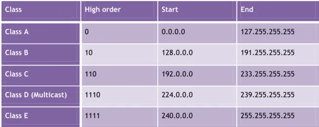
IPv4 is one of the protocols that is widely used in the Internet. All communication across the Internet currently relies on IPv4 protocol. In order to understand this protocol in more detail, first we need to look at the address scheme. IPv4 addressing contains four octets and each octet represents 8 bits of a binary number. The entire address space of IPv4 contains 32 bits of binary number, which mean IPv4 has 2^32 addresses that are equivalent to 4,294,967,296 different addresses. According to [13]. IPv4 contains four classes of address, as shown in Table 2.1 below.
Table 2.1 - IPv4 Address Range
Class High order Start End
Class A 0 0.0.0.0 127.255.255.255
Class B 10 128.0.0.0 191.255.255.255
Class C 110 192.0.0.0 233.255.255.255
Class D (Multicast) 1110 224.0.0.0 239.255.255.255
Class E 1111 240.0.0.0 255.255.255.255
In [14], IPv4 address is written in dot decimal notation and it contains three types of address, which include unicast, broadcast, and multicast address.
2.1.2.2
Internet Protocol Version 6 (IPv6)
Ipv6 is the new version of the Internet protocol which was designed to overcome the shortcoming of IPv4. Authors in [15] stated that “IPv6 was designed to incorporate all of the
patches, changes, and best practices developed from over twenty years of IPv4 Internet engineering, into a new next-generation protocol to support the expansive growth of Internet communications and applications”. The development of IPv6 is not just resolving the
address space but also provide better performance and improvement over IPv4 [16].
It has been almost two decades that IETF NGtrans had proposed IPv6. According to the Authors in [17]. “IPv6 had been proposed at IETF as the next generation of Internet Protocol
at early in the 1990s and it is now ready for practical use after trial phase”. Both IPv4 and
IPv6 have different addressing format, as IPv4 addressing format is written in decimal notation and IPv6 addressing format is written in hexadecimal notation [14].
IPv6 supports unicast, anycast, and multicast address. On the other hand, IPv4 support unicast, anycast, and broadcast address. IPv6 has more efficient forwarding mechanism than
IPv4 due to the 40 bytes fixed header size that allows routers to make faster decisions in forwarding IPv6 packets [18]. There are number of advantages that IPv6 has over IPv4. Next section will discuss in detail the differences between these two protocols.
2.1.2.3
Comparison of IPv4 and IPv6 features
IPv6 packet header has fewer fields when compare to IPv4 header. IPv4 contains fourteen header fields whileIPv6 has eight header fields. However, the size of IPv6 header is double the size of IPv4 header, which means the difference between these two protocols’ headers is 20 bytes. This is due to the length of source and destination IPv6 address in IPv6 header field [19].
There are changes in IPv6 header as compared to IPv4 header:
The Header Length field in IPv4 header is not present in IPv6.
The type of Service field in IPv4 header changed to Traffic Class and Flow Label field in IPv6.
The Source address and destination address of IPv4 contains 32 bit long for each field whereas IPv6 contains 128 bit long for each field.
Time to Live field in IPv4 header changed to Hop Limit field in IPv6.
The Protocol field in IPv4 header changed to Next Header field in IPv6.
IPv6 header does not contain Options and Padding fields.
+ Bits 0-3 4-7 8-15 16-18 19-31
0 Version Header length
Types of Service (now Diffserv and ECN)
Total Length
32 Identification Flags Fragment
Offset
64 Time to live Protocol Header Checksum
96 Source Address (32 bits)
128 Destination Address (32 bits)
160 or 192
Option Data
The IPv4 header fields are described in the following list [20]:
Version: The first header field in an IP packet is the 4-bit version field. For IPv4, this has a value of 4 (hence the name IPv4).
Internet header length: The second field is a 4-bit Internet Header Length (IHL) telling the number of 32-bit words in the header. Since an IPv4 header may contain a variable number of options, this field specifies the size of the header (this also coincides with the offset to the data). The minimum value for this field is 5 (rfc791), which is a length of 5×32 = 160 bits. Being a 4-bit field the maximum length is 15 words or 480 bits.
Type of service: This 8 bit field specifies the datagram's precedence (importance), delay, throughput and reliability.
Total length: Specifies the total length of the datagram (in octets), including the header. Since this field is 16 bits in length, a datagram length of up to 65536 octets can be specified.
Identification: Each datagram assembled receives a unique identification number. If the datagram becomes fragmented, this identification number is used to reassemble the datagram when it is received.
Flags: The flags are the next 3 bits in the datagram. The first is unused. The next is the DF (Don't Fragment) flag. If this is set to 1, then the datagram cannot be fragmented. If the IP layer cannot send datagrams across the network without fragmenting, and the DF flag is set, then no datagrams can be sent. The next flag is MF (More Fragments), and specifies that the current datagram is part of a fragmented message and that more fragments are to follow. If MF is set to 0, then this is the last fragment in the message.
Fragment offset: When MF is set, this field indicates the position of the current fragment relative to the starting fragment, and thereby allows reassembly.
Time to live: The TTL specifies how long a datagram can remain on the network. It is usually set to 15 or 30. Whenever a datagram passes through a host/router, the TTL is decreased by 1. If a datagram reaches 0, the current node discards it and sends a message back to the originator so that it can resend. This process ensures that gateways do not become bottlenecked, and ensures that datagrams do not travel forever if a network path contains a loop.
Protocol: This field contains a code representing the transport protocol of the segment passed to the IP layer. In turn, at the receiving end, this field indicates which upper layer protocol is to receive the data portion of the IP datagram. Common values are 1 for ICMP, 6 for TCP and 17 for UDP.
Header checksum: A form of CRC, the checksum is calculated using a quick algorithm, using data in the IP header only. Because the TTL value is decreased at every node
the datagram passes through, the checksum must also be recalculated at each stage. This checksum gives some protection against corruption.
IP addresses: The 32 bit source and destination IP addresses. Durr.
Options: Additional header fields (called options) may follow the destination address field, but these are not often used. Note that the value in the IHL field must include enough extra 32-bit words to hold all the options (plus any padding needed to ensure that the header contains an integral number of 32-bit words).
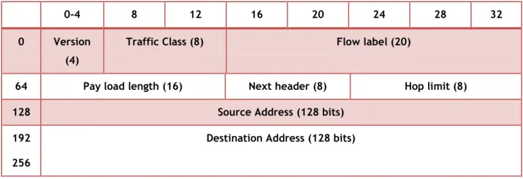
0-4 8 12 16 20 24 28 32
0 Version (4)
Traffic Class (8) Flow label (20)
64 Pay load length (16) Next header (8) Hop limit (8)
128 Source Address (128 bits)
192 256
Destination Address (128 bits)
Figure 2.3 - Internet Protocol version 6 header. The IPv6 header fields are described in the following list [21]:
Version – 4-bit Version number of Internet Protocol = 6.
Traffic Class – 8-bit traffic class field. See Traffic Class.
Flow Label – 20-bit field. See IPv6 Quality-of-Service Capabilities.
Payload Length – 16-bit unsigned integer, which is the rest of the packet that follows the IPv6 header, in octets.
Next Header – 8-bit selector. Identifies the type of header that immediately follows the IPv6 header. Uses the same values as the IPv4 protocol field. See Extension Headers.
Hop Limit – 8-bit unsigned integer. Decremented by one by each node that forwards the packet. The packet is discarded if Hop Limit is decremented to zero.
Source Address – 128 bits. The address of the initial sender of the packet. See IPv6 Addressing.
Destination Address – 128 bits. The address of the intended recipient of the packet. The intended recipient is not necessarily the recipient if an optional Routing Header is present.
2.1.3 Transport Layer
The fourth layer in OSI reference model is Transport Layer. It contains two types of protocols, first is Transport Control Protocol (TCP) which is connection oriented protocol and supports some upper layer protocols like Hypertext Transfer Protocol (HTTP) and Simple Mail Transfer Protocol (SMTP).
The second is User Datagram Protocol (UDP) which is a connection less protocol. Like TCP it also supports some upper layer protocols such as Domain Name System (DNS) and file transfer protocol (FTP). The Transport layers is responsible for the reliability of the link between two end users and for dividing the data that is being transmitted by assigning port numbers to its layer 4 packages, known as segments. The main thing in transport layer protocols is that they have port addresses in their header fields.
2.1.3.1
Transmission Control Protocol (TCP)
TCP is designed to provide a connection oriented ordered reliable byte stream on top of the connectionless unreliable IP [22]. It was also designed to run above IP, providing reliable data transmission with flow control. TCP is a connection-oriented protocol, which means “A user
and network set up a logical connection before transfer of data occurs. Usually, some type of relationship is maintained between the successive data units being transferred through the user/network connection.” [12]. TCP uses sequence numbers and checksum facilities to
ensure that a segment of data is not damaged during the transmission. It also allows retransmission by sending acknowledgement message back to the sender, when the segment is received correctly, a positive acknowledgement (ACK) is returned to the sender, otherwise, a negative acknowledgement (NACK) is returned; in this case, the sender would retransmit the data. In addition, TCP also uses the sequence numbers to deliver the segments in order even if the segments arrive over the network out of order, TCP also checks for the duplication.
Another useful feature provided by TCP is flow-control. It is based on the “sliding-window” technique. A window size value is assigned to the transmitter. The transmitter is only allowed to transmit a specified number of bytes within this window. On receiving of the correct ACKs, the window slides forward. The transmitter must stop the transmission when the window is closed. Another point to mention is the port number. Each application process needs to identity itself by a port number, which is used to identity which application program should receive the incoming traffic. Since the port number allows several programs to communicate concurrently, it can be used to support multiplexing capabilities.
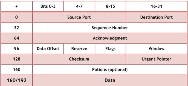
+ Bits 0-3 4-7 8-15 16-31
0 Source Port Destination Port
32 Sequence Number
64 Acknowledgment
96 Data Offset Reserve Flags Window
128 Checksum Urgent Pointer
160 Potions (optional)
160/192
Data
Figure 2.4 - Transmission Control Protocol Header.
The following descriptions summarize the TCP header fields illustrated in Figure 4 [20]:
Source Port and Destination Port: Identifies points at which upper-layer source and destination processes receive TCP services.
Sequence Number: Specifies the number assigned to the first byte of data in the current message. In the connection-establishment phase, this field also can be used to identify an initial sequence number to be used in an upcoming transmission.
Acknowledgment Number: Contains the sequence number of the next byte of data the sender of the packet expects to receive.
Data Offset: This 4-bit field specifies the size of the TCP header in 32-bit words. The minimum size header is 5 words and the maximum is 15 words thus giving the minimum size of 20 bytes and maximum of 60 bytes. This field gets its name from the fact that it is also the offset from the start of the TCP packet to the data.
Reserved: Remains reserved for future use.
Flags: Carries a variety of control information, including the SYN and ACK bits used for connection establishment, and the FIN bit used for connection termination.
Window: Specifies the size of the sender’s receive window (that is, the buffer space available for incoming data).
Checksum: Indicates whether the header was damaged in transit.
Urgent Pointer: Points to the first urgent data byte in the packet.
Options: Specifies various TCP options.
2.1.3.2
User Datagram Protocol (UDP)
UDP is a simple datagram- oriented transport layer protocol. Each output operation
by a process produces exactly one UDP datagram, which causes one IP datagram to be sent. This is different from a stream-oriented protocol such as TCP where the amount of data written by an application may have little relationship to what actually gets sent in a
single
IP datagram. RFC 768 [23] is the official specification of UDP.In addition, UDP is functionally at transport layer protocol. It is connectionless, and does not provide a reliable transport. On the other hand, it gives an application a direct access to the datagram service of the IP layer. The multicast and broadcast services are available by using UDP. The UDP header contains the source port number, destination port number, total length and checksum. (Cisco Networking Academy Program, 2th edition. Cisco Press.2001) [24]. Both UDP and TCP have checksums in their headers to cover their header and their data. Unlike the TCP, UDP adds no reliability, flow-control, or error-recovery functions to IP.
UDP headers contain fewer bytes and consume less network overhead than TCP Because of its simplicity. UDP is useful in situations where the reliability mechanisms of TCP are not necessary, such as in cases where a higher-layer protocol might provide error and flow control. UDP is the transport protocol for several well-known application-layer protocols, including Network File System (NFS), Simple Network Management Protocol (SNMP), Domain Name System (DNS),and Trivial File Transfer Protocol (TFTP).
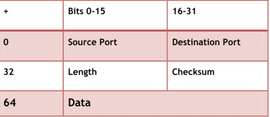
+ Bits 0-15 16-31
0 Source Port Destination Port
32 Length Checksum
64
Data
Figure 2.5 - User Datagram Protocol Header.
The UDP header format contains four fields, as shown in Figure 5 These include source and destination ports, length, and checksum fields [20]:
Source port is the field that identifies the sending port when important and should be assumed to be the port to reply to if needed. If not used, then it should be zero.
Length contains 16-bit field that specifies the length in bytes of the entire datagram: header and data. The minimum length is 8 bytes since that's the length of the header. The field size sets a theoretical limit of 65,527 bytes for the data carried by a single UDP datagram.
Checksum is the 16-bit checksum field that is used for error-checking of the header and data.
2.1.3.3
UDP and TCP Performance
The User Datagram Protocol (UDP) and Transmission Control Protocol (TCP) are the “siblings” of the transport layer in the TCP/IP protocol suite. They perform the same role, providing an interface between applications and the data-moving capabilities of the Internet Protocol (IP), but they do it in very different ways. The two protocols thus provide choice to higher-layer protocols, allowing each to select the appropriate one depending on its needs [25].
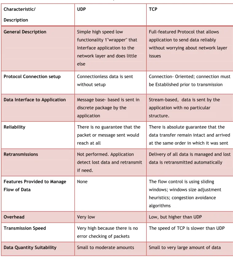
Below is the table which helps illustrate the most important basic attributes of both protocols and how they contrast with each other:
Table 2.2 - UDP and TCP comparative features.
Characteristic/ Description
UDP TCP
General Description Simple high speed low functionality 1"wrapper" that Interface application to the network layer and does little else
Full-featured Protocol that allows application to send data reliably without worrying about network layer issues
Protocol Connection setup Connectionless data is sent without setup
Connection- Oriented; connection must be Established prior to transmission
Data Interface to Application Message base- based is sent in discrete package by the application
Stream-based, data is sent by the application with no particular structure.
Reliability There is no guarantee that the packet or message sent would reach at all
There is absolute guarantee that the data transfer remain intact and arrived at the same order in which it was sent
Retransmissions Not performed. Application detect lost data and retransmit if need.
Delivery of all data is managed and lost data is retransmitted automatically
Features Provided to Manage Flow of Data
None The flow control is using sliding windows; windows size adjustment heuristics; congestion avoidance algorithms
Overhead Very low Low, but higher than UDP
Transmission Speed Very high because there is no error checking of packets
The speed of TCP is slower than UDP
2.1.4 Session Layer
The fifth layer in OSI Reference Model is Session Layer. The Session Layer is responsible for session management i.e. start and end of sessions between end-user applications [26]. It is used in applications like live TV, video conferencing, VoIP etc, in which sender establishes multiple sessions with receiver before sending the data. Session Initiation protocols (SIP) is an example.
2.1.4.1
Presentation Layer
The sixth layer in OSI Reference Model is Presentation Layer. This layer is responsible for presentation of transmitted/received data in graphical mode. Data compression and decompression is the main functionality of this layer. The data encryption is done before transmission in presentation layer.
2.1.4.2
Application Layer
The last layer of OSI Reference Model is Application Layer. This layer organizes all system level applications like DNS, HTTP, Post Office Protocol (POP3), SMTP, Secure shell (SSH), Telnet, E-mail services etc.
The World Wide Web supports two well-known transport protocols which is, HTTP [27] and HTTPS [28]. These two protocols have different costs and provide different security guarantees for the web applications deployed on top of them. At one end, HTTP is inexpensive to use but provides no security guarantees for any web application deployed on top of it. While at the other end, HTTPS is expensive to use but provides three important security guarantees for any web application deployed on top of it. These three security guarantees are (1) server authentication (2) message integrity (3) message confidentiality [29].
In most cases, HTTPS is also augmented with a password protocol in order to provide the added guarantee of client authentication. (Note that HTTP cannot be easily augmented with a password protocol to provide client authentication).
There are two primary differences between an HTTPS and an HTTP connection
HTTPS connects on port 443, while HTTP is on port 80, HTTPS encrypts the data sent and received with SSL, while HTTP sends it all as plain text.
2.1.4.3
HTTP Protocol
The Hypertext Transfer Protocol (HTTP) is a protocol to transmit data at the application layer between hosts. The protocol was designed in 1989 by Tim Berners-Lee at CERN in combination with the Uniform Resource Locator (URL) and the Hypertext Markup Language (HTML). It is a communication scheme to transmit data units which are parts of websites in the WWW and defined in the RFC 2616 [29]. HTTP is a stateless protocol allowing asynchronous connections between client and server. It needs a reliable connection to transmit data. Mostly TCP is used for this purpose although it can run on other reliable protocols too. Up to now there exist two different versions of HTTP: 1.0 and 1.1, the later is a down-compatible extension of the previous version. In HTTP 1.0 the client/server relation can only set up separate connections for every request. In this case a client creates a new TCP connection for each object request separately. The TCP protocol is not optimized for this kind of data transfer. In fact the slow start mechanism will harm the performance of such protocols. As one of the main advantages HTTP 1.1 offers so called persistent connections. In such a connection the client can request multiple objects at once. Hence, there is only one open TCP connection for the whole webpage. The drawback to this method is the fact that there are more open connections that must be handled by the servers. The second performance improvement in HTTP 1.1. is pipelining. This feature enables the client to request multiple objects without waiting for the response from the server. In combination with the persistent connection this feature fills the available resources much more efficiently. In general the HTTP header may hold optional information not standardized, which allows special applications to implement modified data communications.
2.1.4.4
HTTPS Protocol
Hypertext Transfer Protocol Secure (HTTPS) is a widely used communications protocol for secure communication over a computer network, with especially wide deployment on the Internet. Technically, it is not a protocol in itself rather, it is the result of simply layering the Hypertext Transfer Protocol (HTTP) on top of the Secure Sockets Layer/ Transport Layer Security SSL/TLS protocol, thus adding the security capabilities of SSL/TLS to standard HTTP communications [30].
In its popular deployment on the Internet, HTTPS provides authentication of the web site and associated web server that one is communicating with, which protects against Man-in-the-middle attacks. Additionally, it provides bidirectional encryption of communications between a client and server, which protects against eavesdropping and tampering with and/or forging the contents of the communication [31]. In practice, this provides a reasonable guarantee that one is communicating with precisely the web site that one intended to communicate
with (as opposed to an imposter), as well as ensuring that the contents of communications between the user and site cannot be read or forged by any third party.
In the past, HTTPS connections were primarily used for payment transactions on the World Wide Web, e-mail and for sensitive transactions in corporate information systems. In the late 2000s and early 2010s, HTTPS began to see widespread use for protecting page authenticity on all types of websites, securing accounts and keeping user communications, identity and web browsing private.
2.1.5 Network security
Network security refers to any activities designed to protect your network. It consist of the technologies and processes that are deployed to protect network from internal and external threats.
Network security involves all activities that organizations, enterprises, and institutions undertake to protect the valve and ongoing usability of assets and the integrity and continuity of operations. Effective network security targets a variety of threats and stops them from entering or spreading on the network.
System and network technology is a means technology for a wide variety of applications. Security is essential to networks and applications. Although, network security is a vital requirement in emerging networks, there is an important lack of security methods that can be easily implemented. There exists a “communication gap” between the developers of security technology and developers of networks.
Network design is a well‐developed process that is based on the Open Systems Interface (OSI) model. The OSI model has several advantages when designing networks. It offers modularity, flexibility, ease‐of‐use, and standardization of protocols. The protocols of different layers can be easily combined to create stacks which allow modular development.
The implementation of individual layers can be changed later without making other adjustments, allowing flexibility in development. In contrast to network design, secure network design is not a well-developed process. There isn’t a methodology to manage the complexity of security requirements. Secure network design does not contain the same advantages as network design.
When considering network security, it must be emphasized that the whole network is secure. Network security does not only concern the security in the computers at each end of the communication chain. When transmitting data the communication channel should not be vulnerable to attack. A possible hacker could target the communication channel, obtain the data, decrypt it and re‐insert a false message. Securing the network is just as important as securing the computers and encrypting the message.
When developing a secure network, the following need to be considered [57]:
Access – authorized users are provided the means to communicate to and from a particular network
Confidentiality – Information in the network remains private
Authentication – Ensure the users of the network are who they say they are
Integrity – Ensure the message has not been modified in transit
Non‐repudiation – Ensure the user does not refute that he used the network
2.1.5.1
Importance of Network Security
Network security is important for a variety of reasons. First of all, it is important to ensure the company's reputation will not be marked by a security breach leaking customers' information. Large, small, known and unknown companies are all at risk to an attack led by a hacker. One security breach and the reputation of the company can immediately take a turn for the worse.
Once a company is educated about their network's strengths and weaknesses, they will gain a better understanding of areas they may be at risk to an attack and be able to take appropriate measures to pinpoint areas where security needs to be reinforced. Network security helps to protect the networks and the network-accessible resources from unauthorized access, and consistent and continuous monitoring and measurement of its effectiveness combined together. The primary goal of network security is to provide controls at all points along the network perimeter which allows access to the network and only let traffic pass if that is authorized, valid and of acceptable risk.
The purpose of network security is to protect networks, network devices and network messages from unauthorized access, usually by outsiders:
To provide control at all points along the network perimeter in order to block network traffic that is malicious, Unauthorized or that otherwise presents risk to the network.
To detect and respond to attempted and actual intrusions through the network.
To prevent network messages that is sent across networks from being intercepted or modified.
Network security controls cannot completely eliminate risk. The goal is to minimize risk as much as possible and to avoid unnecessary or excessive risk. The goal of network security is really to 'enable' network connectivity. Without network security, the risks/costs of network connectivity would be very expensive.
2.1.5.2
Network Security Threats
Security threat is a condition or event with potential to harm network resources in the form of destruction, disclosure, fraud etc. Network security threats include impersonation, eavesdropping, denial-of-service, packet replay and packet modification. Security threat can be categorized into four parts and these categories are the ways or forms through which threats can be carried out on a network. These threats can be categorized as unstructured versus structured, and external versus internal:
Unstructured Threats: Unstructured security threat is the kind of threat created by
an inexperienced person trying to gain access to a network. They commonly use common hacking tools, like shell scripts, and password crackers. A good security solution should easily thwart this kind of attack. In other words, these kinds of hackers could not be underestimated because they can cause serious damage to network.
Structured Threats: Unlike unstructured threats, structured threat hackers are well
experienced and highly sophisticated. They use sophisticated hacking tools to penetrate networks and they can break into government or business computers to extract information. On certain occasions, structured threats are carried out by organized criminal gangs or industry competitors.
2.1.5.3
External Threats
External threats can arise from individual or organization working outside of a company who do not have authorized access to the computer systems or network. They work their way into a network mainly from the Internet or dialup access servers. External threats can vary in severity depending on the expertise of the attacker, Both experienced and inexperienced hackers could pose external threats.
2.1.5.4
Internal Threats
An internal security threats occurs when someone from inside your network creates a security threats to your network. Interestingly, the CSI (Computer Security Institute) study has found that, of the 70 percent of the companies that had security breaches, 60 percent of these breaches come from internal sources. Like external threats, the damage that could be caused by such a hacker depends on the expertise of the hacker. (Orbit-Computer Solutions 2012).
2.2 Network Traffic
With the increasing knowledge in Internet applications and the need to transmit and receive information in a timely, secured and accurate manner, the need to study the network traffic and analysis for effective and efficient decision making by its users, has become an interesting research area.
This scientific approach involves collection and gathering of network traffic data over a period of years, processing, analysing and interpreting them into a useful information for effective and efficient decision making. The moment the data are collected from a particular point on your network for a period of time, the real fun begins that is performing traffic analysis on the data.
The methodology adopted varies from place to place. Different researchers tend to adapt different approaches depending on the environments and the polices governing the place. However, the general guide is that if you permit everything that isn't explicitly denied, then you should look for those items that are explicitly denied. If you deny everything that isn't explicitly permitted, then you'll need to look for those items that aren't explicitly permitted. It is pertinent to point out that in many environments, no single person will know what activity is really unauthorized, particularly on a server-by-server or host-by-host basis. In which cases, there is need to consult the network polices governing the environment. This stage of traffic polices and data pre-processing lead us to the statistical analysis of these data which is known as network traffic monitoring and analysis.
2.2.1 Network Monitoring
This is the process to monitor a computer network to prevent that the network goes too slow or to look out for failing systems, including notifying the network administrator via email, pager or other alarms [58].
Network monitoring is the use of grouping and analysis tools to accurately determine traffic flows, utilization, and other performance indicators on a network [59]. A good monitoring tools gives you both hard numbers and graphical aggregate representations of the state of the network. This helps the network administrator to visualize precisely what is happening in the network, so as to know where adjustments may be needed.
These tools can help answer critical questions, such as:
What are the most popular services used on the network?
Who are the heaviest network users?
At what time of the day is the network most utilized?
What sites do your users frequent?
Are there indications of an unusual network situation that is consuming bandwidth or causing other problems?
Is our Internet Service Provider (ISP) providing the level of service that we are paying for?
This should be answered in terms of available bandwidth, packet loss, latency, and overall availability.
And perhaps the most important question of all:
Do the observed traffic patterns fit our network planning and expectations?
There are two types of Network monitoring techniques, active monitoring and passive monitoring. Active monitoring reduce system overhead by using small number of probe packets that have smaller sizes compare to real data packet so that performance measures may not be accurate. While Passive monitoring monitors a lot of data packets, it has system overhead problem so that its performance is more accurate and reliable than active monitoring [60].
2.2.2 Traffic Flow
The environment of Internet traffic can better be understood by knowing the concept of the flow. Traffic flow or network flow is a sequence of packets from a source computer to a destination, which may be another host, a multicast group, or a broadcast domain. RFC 2722 [61] defines traffic flow as "an unreal logical equivalent to a call or connection. RFC 3697 [62] defines traffic flow as "a sequence of packets sent from a particular source to a particular uncast, any cast, or multicast destination that the source desires to label as a flow. A flow could consist of all packets in a particular transport connection or a media stream. Flow is also defined in RFC 3917 [63] as a set of IP packets passing an observation point in the network during a certain time interval.
Alternatively, the definition of flow may also be coined as, a series of packets that share the same source IP, destination IP, source port, destination port and the protocol. This is most commonly known as five-tuple IP flow, which is an aggregation of individual flows.
Network flow data symbolizes a summary of sessions between two end hosts. It further aids in network analysis and security issues. Flow data is autonomous of packet payloads. The flow tool or analyzer is dependent on the amount of information collected from packet headers and its important metrics. In addition, the network flow data deeply enhances the visualization of discrete network events such as protocol analysis or length distribution without the need for payload analysis.
The knowledge of flow data aids in understanding how different flows compete in a network to acquire network resources. Packets having similar five-tuple information belong to the same flow. The most significant thing to remember is that a network flow can be considered either as unidirectional flow or bidirectional flow. In unidirectional flow, the flow attribute is categorized in one direction i.e. from source to destination or vice versa. Whereas, in a bidirectional flow, the attributes are categorized considering both directions.
2.2.3 Traffic Profiling
As the Internet continues to grow in size and complexity, the challenge of effectively provisioning, managing and securing it has become inextricably linked to a deep understanding of Internet traffic. Although there has been significant progress in instrumenting data collection systems for high speed networks at the core of the Internet, developing a comprehensive understanding of the collected data remains a daunting task. This is due to the vast quantities of data, and the wide diversity of end-hosts, applications and services found in Internet traffic. Because of these challenges that will encounter every day in the Internet, there is need for us to use traffic profiling in our network plan.
Traffic profiling is the ability to look at the network traffic and identify potential security risks. Today network profiling should include not only the local area network traffic but also wireless traffic as well as any traffic that flowing through the routers and firewalls.
2.2.4 Traffic Analysis
Traffic analysis is the science of extracting information from metadata, or otherwise known as traffic data, produced by a communication. These include the routing data, length and timing of the communication stream. Recent work in this area includes using timing information to reduce the entropy of passwords sent using SSH [64] and guessing if a particular web page is already locally cached by a user [65]. Research into anonymous communication has also provided some insights about how the shape of traffic contained in a channel can be used to trace the communication. The onion routing project [66] presented strong evidence for the need to use dummy cover traffic in order to hide these patterns. Traffic analysis of HTTP transactions through anonymizing proxies has been mentioned in [67] and [68]. In [67] Hintz analyzes traffic packet lengths at the TCP level, in order to attack the SafeWeb [69] service.
Traffic analysis can be used to extract a variety of information. It can be used for identification, when the information extracted is used to find out who the sender of some data is, or which particular network card is active. It can also be used for profiling when the aim of the analysis is to extract some information about the target, such as their type or