of Chemical
Engineering
ISSN 0104-6632 Printed in Brazil www.scielo.br/bjce
Vol. 35, No. 02, pp. 679 - 690, April - June, 2018 dx.doi.org/10.1590/0104-6632.20180352s20160495
THEORETICAL MODELS FOR RATES OF
HETEROGENEOUS REACTIONS DURING
COMBUSTION AND GASIFICATION OF LIQUID
FUELS IN FLUIDIZED BEDS
Marcio L. de Souza-Santos
1*1University of Campinas (UNICAMP), Faculty of Mechanical Engineering,
Department of Energy, Cidade Universitária, C. Postal 6122, Campinas, São Paulo 13083-970, Brazil.
(Submitted: August 15, 2016; Revised: December 19, 2016; Accepted: March 24, 2017)
Abstract - Two mathematical models to allow computations of chemical species production or consumption
rates by heterogeneous reactions taking place during combustion and gasification of liquid fuels sprayed on or injected into fluidized beds of solid particles are proposed. The possibilities envisaged here are called: the CIP (Coated Inert Particles) and the CSP (Coke Shell Particle) models. The former assumes that the injected liquid fuel immediately coats the fluidized inert particles in the bed and then goes through pyrolysis, combustion and gasification reactions. The latter presumes that the liquid fuel drops go through fast pyrolysis before meeting any
inert particles and the remaining coke hollow particles react with gases in the bed. Analytical solutions for various
geometries of the inert particles in the bed are presented. The work does not include the governing equations which constitute the whole mathematical model of fluidized-bed reactors. Such can be found elsewhere. The present work concentrates only on the theoretical aspects. Experimental tests would allow verification if they properly represent the processes of liquid consumption during combustion and gasification processes consuming liquid fuels in fluidized beds and which model would better fit each individual situation.
Keywords:Liquid Fuels, Combustion, Gasification, Mathematical Models, Fluidized-Bed.
INTRODUCTION
Fluidized-Bed technology has been successfully applied for cases of solid fuels as energy sources. The
various advantages of fluidized beds, either bubbling,
circulating, or entrained over more conventional
combustion and gasification techniques are listed
elsewhere (Basu, 2016; Kunii and Levenspiel, 1991; Kunii and Levenspiel, 1997; Geldart, 1986; de Souza-Santos, 1987; de Souza-Santos, 2010).
Fluidized beds have been particularly useful when dealing with high-moisture biomasses, municipal solid residues, high-ash coals and other low heating-value fuels (de Souza-Santos, 2010;, Muskala et al., 2011).
During the years, many models have been developed to allow predictions of the behavior of existing units as well and optimizations of future ones. The list of those is too extensive, but many are described or listed in reviews (Gomez-Barea and Leckner, 2010; Philippsen et al., 2015; Alagoz, 2006;
Saraiva et al., 1993). Nonetheless, no model has been found in the literature including the alternative of
liquid fuel feeding into fluidized beds.
The present development
An existing simulation program (www.csfmb.com) has been validated (de Souza-Santos, 1987, 1989, 1994a, 1994b, 2007, 2008, 2009, 2010; Rabi and de Souza-Santos, 2003, 2004, 2008; Krzywanski et al., 2016; Englebrecht et al., 2011) and used in studies involving various possibilities and consuming many
fuels, including low-quality ones (Muskala et al., 2011;
de Souza-Santos, 1989, 1994a, 1994b, 2007, 2008, 2009, 2010, 2015; Rabi and de Souza-Santos, 2003, 2004, 2008; Krzywanski et al., 2016; Englebrecht et al., 2011; de Souza-Santos and Chaves, 2012a, 2012b, 2012c; de Souza-Santos and Ceribeli, 2012, 2013; de Souza-Santos and Beninca, 2014; de Souza-Santos and Lima, 2015; de Souza-Santos et al., 2015).
In many situations, fluidized beds require inert
solids, such as sand or alumina, as temperature
regulator and to allow more stable fluidization
(Basu, 2016; Kunii and Levenspiel, 1991; Kunii and Levenspiel, 1997; Geldart, 1986; de Souza-Santos, 1987; de Souza-Santos, 2010). Ash particles, detached from the feeding solid fuel, can replace part or even the total amount of that inert material.
In addition to solid fuels, liquids or slurries
are also an important segment of the spectrum found in industry. Among them there are heavy or viscous oils, whose combustion in pulverized form is cumbersome. Furthermore, several works have explored the application of residual hydrocarbon to enrich low heating value solid fuels to allow their ignition, as well as improve the combustion
or gasification processes (Breault, 2010). Amid
those, glycerol has shown particular interest since it is a byproduct of biodiesel production, which has increased substantially in many countries (Leonetia et al., 2012; Wei et al., 2011; Sricharoewnchaikul and Atong, 2012; Manara and Zabanioutou, 2016; Czernichowski, 2009; Fosso-Kankeu et al., 2015; Maintinguer et al., 2015; Pagliaro and Rossi, 2010). For instance, just the Brazilian output should reach 4.1 million m3 in 2016 (Barros, 2015). Since glycerol
represents around 11% of biodiesel production, its rate of generation would also increase fast in the coming years (Dasari et al., 2005; Schultz et al., 2014).
An alternative for the utilization of those liquid fuels is their injection into fluidized bed boilers or gasifiers.
BASIC MODELS
The following possibilities can be visualized:
a) As the liquid fuel enters the fluidized bed, it
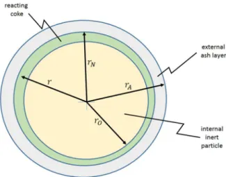
immediately coats the inert solid particles. Then, the fuel goes through pyrolysis or devolatilization and the resulting coke layers remain on the inert particles. Then, those layers are attacked by gases. This model is called here CIP (Coated Inert Particle) and the situation is illustrated by Figure 1. The Appendix describes how it can be applied for each situation where the supporting solid has
a particular basic shape, i.e., planar or flat,
cylindrical, or spherical.
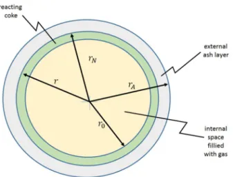
b) As the liquid fuel is sprayed into the bed, the
drops go through pyrolysis before having the opportunity of meeting any inert particle. A hollow coke shell forms from each fuel drop after the volatiles escape from its interior through small holes in the respective shell. Then, the remaining shell of that hollow sphere of coke reacts with the gases. The average size among the spheres is assumed to be the same as the average drop size in the original sprayed fuel. This model is called here CSP (Coke Shell Particle) and the situation is illustrated by Figure 2.
Before describing the mathematical models, it is important to stress that the present work assumes isothermal conditions in the layer of fuel and inert particles. The local temperature of particles, as well as temperature, pressure, and composition of the surrounding gas, should be given by a comprehensive
model for fluidized-bed equipment. The governing equations that constitute the mathematical model of fluidized-bed reactors can be found elsewhere (de
Souza-Santos, 2010). The only objective here is to
present the equations proposed for the reaction rates between gases and the liquid fuel injected into the reactor with fluidized inert solid particles.
The treatment for a single heterogeneous reaction i, in which a chemical component j of the surrounding gas is consumed or produced, has been presented by de Souza-Santos (2010). In any case, the fundamental
equation for conservation of species leads to
(1)
The Laplacian operator is generalized as:
(2)
the coefficient p takes the following possible values:
0 for plane geometry, 1 for cylindrical, and 2 for
spherical. Here:
(3)
(4)
The Thiele coefficient is given by:
(5)
On the above, it has been assumed that all reaction
rates could be written as:
(6)
which is valid for most of the combustion and
gasification reactions. For those, the reaction order
n varies between 0 and 2. However, the main cases of carbon-oxygen and carbon-water reactions-which
control most of the combustion and gasification processes-follow a first order behavior. A list of
several reactions found in those processes as well
their kinetic coefficients are presented elsewhere
(de Souza-Santos, 2010).
The basic equations to allow computation of the
CIP and CSP models are present below.
Coated Inert Particle (CIP) Model
Figure 1 illustrates the CIP model. The inert particle, coated by a coke layer, may present three
basic shapes: plane (in the case of chips), cylindrical (in the case of pellets or fibers), and spherical or
almost spherical. As detailed in the Appendix, the solutions can be condensed into a single formula for the rate of consumption or production of component j by reaction i as
(7)
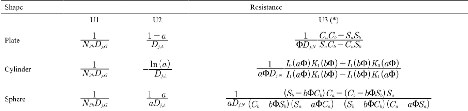
The sum that appears in the denominator represents the three resistances in series for mass transfers of chemical species j that depend on the inert particle original shape. Table 1 summarizes the various
possibilities. The first parameter U1 represents the resistance to the mass transfer at the gas boundary layer, U2 the resistance at the ash layer, and the U3 the combined resistances of reacting gas mass transfer trough the reactive coke layer and its respective chemical reaction with the coke material. The various resistances for the basic geometries are summarized at Table 1. An example of deduction is shown in the Appendix.
Figure 2. Scheme for the CSP model.
y
y
n2 2
4
=
U
x
dx
d
x
dx
d
p p
2
4
=
-S
X
x
r
r
A
=
y
, ,
,
j j eq
j j eq
t
t
t
t
=
-
-3
u
u
u
u
r
D
k
,
, ,
/
A
j N
i j j eq
n 1 1 2
t
t
U
=
3
-u
u
Q
V
#
&
r
ik
i j j eq, nt
t
=
-u
Q
u
u
V
r
r
U
1
, , jA
k k
j j eq
1 3
t
t
=
3-=
u
u
Coke Shell Particle (CSP) Model
Figure 2 illustrates the situation for the CSP model. Here just the spherical shape is possible.
The first aspect to face is to estimate the radius of the internal space filled with gases.
The original mass of the droplet is given by
(8)
On the other hand, the mass of the coke before the formation of ash over it, is provided by
(9)
However,
(10)
Therefore,
(11)
The deduction for the resistances are presented in the Appendix. These resistances can be employed
in Eq. (7) to compute the rate of consumption or
production of gas component j by reaction i.
DISCUSSION
According to Equation 58 of the Appendix, in the
case of CSP model, if no mass transfer at the internal cavity surface takes place (i.e., N2 = 0), the parameter
equals the variable a and the resistance forms reproduce
the CIP case for spherical geometry.
Another interesting aspect of that case can be appreciated by noticing that the parameter gj (Eq. 45 in the Appendix) is a function of the average
concentration inside the cavity. At the beginning of
cavity formation, the concentration would be equal
to those obtained from the pyrolysis. After a while,
the composition tends to equalize the concentration of the equilibrium atmosphere in which the particle
is immersed. Therefore, for long exposure times, gj would tend to zero. This situation reproduces the case where N2 = 0.
CONCLUSIONS
The possibility of using the fluidized-bed technique for combustion and gasification of liquid fuels is known. In those cases, the liquid is sprayed over or injected into the bed where inert solid is fluidized.
The adaptation of existing simulation models
to such situations required methods to compute
the kinetics for heterogeneous reactions. To allow
that, two possible approaches are proposed here:
the CIP (Coated inert Particle) Model and the CSP (Coke-Shell Particle) Model. The work introduces the analytical solutions for those models, as well as
for cases of different basic shapes of inert particles
present in the bed.
The present proposals are theoretical. Future
publications might confirm the deductions made here
and which model would better represent the process in each situation.
APPENDIX
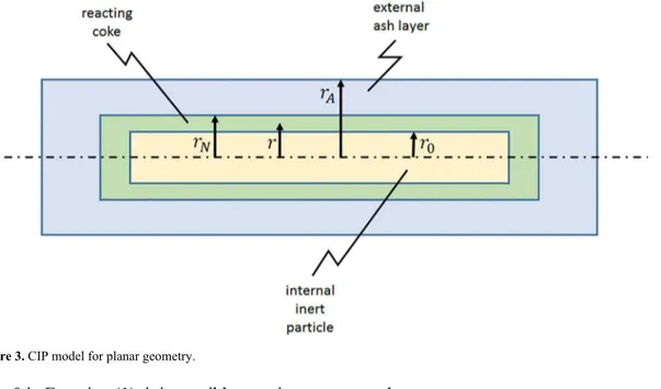
CIP Model for Plane Geometry
Figure 3 illustrates the situation where the slab or chip is assumed to have a thickness much smaller than any other dimension. Therefore, all variations occur in the r direction, which is normal to the surface with largest area.
Table 1. Formulas to compute the mass transfer resistances in the case of CIP model.
Shape Resistance
U1 U2 U3 (*)
Plate N D1
,
Sh j G D
a
1
,
j A
-D S C C S
C C S S
1
,
j N a b a b a b a b
U -
-Cylinder
N D
1
,
Sh j G
( ) ln
D a
,
j A
- a D (( )) (( )) (( )) (( ))
I a K b I b K a
I a K b I b K a
1
,
j N 1 1 1 1
0 1 1 0
U U U U U
U U U U
-+
Sphere
N D
1
,
Sh j G aD
a
1
,
j A
-( )( ) ( )( )
( ) ( )
aD C b S S a C S b C C a S
S b C C C b S S
1
,
j N b b a a b b a a
b b a b b a
U U U U
U U
- - - -
-- -
-(*)Here: Sa=sinh(aΦ), Sb=sinh(bΦ), Ca=cosh(aΦ), Cb=cosh(bΦ)
m
4
3
r
A 3r
t
=
k k
m
c4
3
r
Ar
c 303
r
t
=
Q
-
V
m
c=
m
kR1
- -
f
Vf
MW=
m f
kr
r
1
f
/
A
c 0
1 3
Using p = 0 in Equation (1), it is possible to write
(12)
For the ash layer where no reaction takes place, it leads to
(13)
and
(14)
where the parameter a is given by:
(15)
One boundary condition can be set for the external surface, or at x=1, where continuity imposes that the
mass transfer by diffusion of the reacting gas j equals the mass transfer by convection, or:
(16)
or
(17)
where the Sherwood number is:
(18)
and:
(19)
It should be noticed that the coefficient Dj is the
diffusivity of component j into the phase in which the
process takes place. If that phase is the particle core,
or nucleus, the parameter is called the "effective" diffusivity of j in that porous structure, which is
represented by Dj,N. A similar notation will be used for
the diffusivity of j through the shell of inert porous solid
that coats the core, or Dj,A. For the boundary layer of gas, which surrounds the particle, the value is the average
diffusivity of j through the gas mixture that constitutes
the layer, or Dj,G. As it was shown long ago by Walker
et al. (1959), the values for effective diffusivity can be correlated to the gas-gas diffusivity Dj,G.
From (12) and (13) in (17) it is possible to write
(20)
Therefore,
(21)
In the reacting coke layer, Eq. (12) becomes a Bessel equation and its solution can be written as:
(22)
Where:
(23)
dx
d y
y
2 2
2
U
=
,
dx
dy
A
1a
#
X
#
1
=
,
y
=
A x
1+
B
1a
#
X
#
1
a
r
r
A N
=
D
dr
d
D
dr
d
, ,
, ,
j G j
r r j A j r r
G j j surf
A A
t
t
b t
t
=
=
-3
= + =
-u
u
u
u
Q
V
y
N
y
D
D
N
y
1
1
1
1
1
, , Sh
j A j G
1
=
-
=
-l
Q V " Q V% " Q V%N
D
r
, Sh
j G G A
b
=
N
N
D
D
, , Sh
j A j G
1
=
B
N
N
A
1
1
1
1 1
1
= -
+
,
y
A x
11
N
N
1
a
X
1
1 1
#
#
=
A-
+
D+
,
sinh
cosh
y
=
A
2Q
x
U
V
+
B
2Q
x
U
V
b
#
X
#
a
b
r
r
A 0
=
A boundary condition can be found at x = b. As the inert material is impermeable to the reacting gas, the mass transfer is zero at that interface, or
(24)
Therefore, Eq. (22) becomes:
(25)
The other condition comes from continuity of the
mass transfer at the coke-ash interface, or:
(26)
Equations (13) and (25) lead to:
(27)
Therefore,
(28)
In addition, the concentrations match at that interface or y(a-)=y(a+). Thus, the above equation can
be combined with Eq. (21) to give:
(29)
where:
(30)
The rate of consumption or production of component j is given by the mass transfer of that component at the
external layer, or:
(31)
Finally, using Eq. (13), it is possible to obtain the
resistances listed for the plane geometry as shown in Table 1.
The deductions for other geometry (p = 1 and p = 2) follow the same path.
The values of the parameters a (Eq. 15) and b (Eq. 23), or dimensionless variables, need to be
addressed. It is easy to show that they can be computed
by:
(32)
and
(33)
where f represents the fraction of the fixed-carbon,
originally in the feeding fuel, which is converted into
gases, and d is the film thickness. This thickness can
be easily computed by assuming that all particles
present in the bed are equally and uniformly coated by the feeding liquid. Given the very high circulation rates of particles in a bubbling or circulating fluidized
bed, this should not be very far from reality.
CSP Model
From Equations (1) and (2)
(34)
(35)
The boundary condition (17) leads to
(36)
where N1 is given by Eq. (19).
For the coke reacting layer, the following can be written
(37)
and the solution of that Bessel equation is
(38)
From the continuity for the mass transfer at the
coke-ash interface (Eq. 26), it is possible to write:
(39)
dx
dy
0
x=b
=
,
cosh
sinh
y
B
x
tgh b
x
b
X
a
2
#
#
U
U
U
=
-Q
Q
Q
V
V
V
#
&
D
dx
dy
D
dx
dy
, ,j N x= -a
=
j A x= +asinh
cosh
B
A
D
D
a
tgh b
a
, , j N j A 2 1 1U
U
U
U
=
-Q
Q
Q
V
V
V
#
&
A
D
D
N
N
a
1
1
, , j N j A 1 1 1p
+
+
-=
,
sinh
cosh
cosh
sinh
y
A
D
D
a
tgh b
a
x
tgh b
x
b
X
a
, , j N j A 1
#
#
U
U
U
U
U
U
U
=
-Q
Q
V
V
Q
Q
V
V
Q
Q
V
V
sinh
cosh
cosh
sinh
a
tgh b
a
a
tgh b
a
1
p
U
U
U
U
U
U
U
=
Q
Q
V
V
-
-
Q
Q
V
V
Q
Q
V
V
r
D
dr
d
r
D
dx
dy
, , , ,j j A
j r r
A
j A j j eq
x 1 A
t
t
t
=
=
3-= =
u
Q
u
u
V
a
d
d
f
2
2
, , P inert P inertd
d
=
+
+
b
d
d
2
, , P inert P inertd
=
+
dx
dy
A x
1 2=
-,
y
A x
1B a
X
1
1
1
#
#
=-
-+
B
11
1
N
N
A
1 1
1
= -
-x y
2m
+
2
xy
l
-
x
2U
2y
=
0
,
sinh
cosh
y
A
2x
x
B
2x
x
b
#
X
#
a
U
U
=
Q
V
+
Q
V
sinh
cosh
cosh
sinh
D
D
A
A
a
a
a
B
a
a
a
0
, , j A j N 1 2 2
U
U
U
U
U
U
+
-+
Q
-
=
The following comes from the continuity or equality of concentration at the two sides of the interface:
(40)
At the internal surface of the shell
(coke-cavity-gas), the following is required:
(41) or: (42) where: (43) and (44) (45)
The combination of above equations leads to:
(46)
or
(47)
The continuity of mass transfer rate at the coke-ash
interface leads to:
(48)
Equality of concentration at the coke-ash interface, to:
(49)
A2, and B2 can be eliminated from the three above
equations in order to obtain A1 as:
(50) where: (51) (52) (53) (54) Finally, (55) (56) (57) Here (58) with (59)
sinh
cosh
A
a
N
N
A
a
a
B
a
a
1
1
1
1 1 1 2 2U
U
+
-
+
+
=
TQ
Q
V
YV
D
,d
dr
D
,d
dr
, ,
j N j
r r j G j r r
ca j r r j ca
0
0
t
t
b
t
t
=
=
-o o = + = -= 0u
u
u
u
Q
V
y b
N
y b
D
D
N y b
, , , Sh ca j N j G 2
c
c
=
o+
=
+
l
Q
V
"Q
V
% "Q
V
%N
,D
r
, Sh ca j G ca 0b
=
o oN
N
,D
D
, , Sh caj N j G
2
=
o, ,
, ,
j
j j eq
j ca j eq
c
=
t
t
-
-
t
t
3 o
u
u
u
u
sinh
cosh
cosh
sinh
A
N
b
b
b
b
b
B
N
b
b
b
b
b
N
1
1
j 2 2 2 2 22 2
c
U
AU
U
U
U
U
+
-
+
+
-
=
T TQ
Q
Q
Q
Y YV
V
V
V
#
#
&
&
A
N b S
bC
B
N b C
bS
N
b
1
1
b b
b b j
2 2 2
2 2 2
c
U
U
+
-
+
+
-
=
Q
Q
V
V
" "
$
$
A
S
aC
B
C
aS
D
D
A
, ,
a a a a
j N j A
2
!
-
+
U
$
+
2!
-
+
U
$
=
1A S
2 aB C
2 aA
11
a
1
N
N
a
1 1
+
=-
T+
-
Y+
/
A
aC
S N
b
C C
C C
N
b C C C
C S
a N
N
C C C
C C
D
D
C C C
C S
1
1
1
, ,
a j
j a a
j N j A
a a
1
1 2 2 1 4 2 3
2 2 3 1 2
1
1 1 4 2 3
1 1 2
c
c
=
-
-
+
-+
-
-
+
-S
Q
Q
Q
Q
Q
X
V
V
V
V
V
R
T
SS
SS
SS
SS
SS
#
V
X
WW
WW
WW
WW
WW
&
C
1=
S
b+
N bS
2 b-
U
bC
bC
2=
C
b+
N bC
2 b-
U
bS
bC
3=
U
aC
a-
S
aC
4=
U
aS
a-
C
aU
N D
a
1
, Sh j G
1
=
~
U
1
D
a
1
, j A
2
=
-
~
U
D
1
, j N
3
~
N
=
a
N b
C
jS
aC
1
2 2
3
~
= -
c
Q
-
N
V
C C
C C
C C
aC S
a1 4 2 3
1 2
-NOMENCLATURE
a, A, b, B, C - parameters (dimensionless)
Ca, Cb - see observation under Table 1 (dimensionless) dP - particle diameter or thickness in the cases of slabs Dj - average equivalent or effective diffusivity of chemical species j (the second subscript indicates the
medium) (m2 s-1)
f - fractional conversion of fixed-carbon originally in
the fuel (dimensionless)
I - Modified Bessel function of the first kind (subscript
indicates order)
ki - rate coefficient of reaction i [s-1 (kmol-1 m3)n-1]
K - Modified Bessel function of the second kind
(subscript indicates order)
m - mass (kg)
n - reaction order
N - parameter (dimensionless)
NSh - Sherwood number
p - parameter to indicate the geometrical form
r - radial co-ordinate (m). In cases of slabs or chips, it
is the distance between the centerline of the slab and
the outer surface (with the largest area) of the ash layer
(m).
rĩ'''- reaction rate (kmol m-3 s-1)
rĩ'' - reaction rate based on the external area of the particle (kmol m-2 s-1)
Sa, Sb - see observation under Table 1 (dimensionless) U - resistance to mass transfer (s m-2)
x - dimensionless co-ordinate
y - dimensionless concentration of reacting gas
Greek Letters
β - mass transfer coefficient (m s-1)
γ - dimensionless concentration
δ - film thickness (m)
Φ - Thiele modulus or coefficient (dimensionless) ρ - density (kg m-3)
j
t
u - molar concentration of the reacting chemical species j (kmol m-3)
ξ - parameter (dimensionless) ω - parameter (dimensionless)
Ξ - parameter (dimensionless)
Subscripts
A - ash
c - coke
Eq - at equilibrium condition
G - gas phase
i - chemical reaction number
j - chemical component
l - liquid
M - moisture in the original fuel
N - active or reacting coke layer
O - original or internal
V - volatile in the original fuel
∞ - at conditions in the surrounding gas and far from
the reacting particle
REFERENCES
Alagoz, D. E., Mathematical Modeling of Fluidized Bed Combustors with Radiation Model, M.Sc. Thesis presented to The Graduate School of Natural and Applied Sciences of Middle East Technical University, 2006.
Barros, S., Brazil’s Biofuels Annual Report, Gain
Report Number: BR15006, USDA Foreign Agricultural Service, 2015 (on line: http://gain.
fas.usda.gov/Recent%20GAIN%20Publications/ Biofuels%20Annual_Sao%20Paulo%20ATO_ Brazil_8-4-2015.pdf, accessed on September 2016)
Basu, P., Combustion and Gasification in Fluidized Beds. Miami, FL: CRC Press, 2006. ISBN
Breaut, R. W., Gasification Processes Old and New: A
Basic Review of the Major Technologies. Energies,
3(2) 216-240 (2010). DOI: 10.3390/en3020216
Czernichowski, A., Conversion of waste glycerol into synthesis gas, In 19th Int. Symp. on Plasma Chem. (ISPC-19), Bochum, Germany, July 26 (Vol. 31, p. 4) (2009) ECP - GlidArc Technologies, La Ferté
St. Aubin, France, http://www.ispc-conference.org/
ispcproc/ispc19/697.pdf
Dasari, M. A., Kiatsimkul, P. P., Sutterlin, W. R., and Suppes, G. J., Low-pressure hydrogenolysis of glycerol to propylene glycol, Appl. Catal. A Gen., 281(1-2), 225-231 (2005).
de Souza-Santos, M. L., Modelling and Simulation
of Fluidized-Bed Boilers and Gasifiers for
Carbonaceous Solids. Ph.D. Dissertation,
University of Sheffield, United Kingdom, 1987.
etheses.whiterose.ac.uk/1857/1/DX196027.pdf (accessed on 03/03/2014)
de Souza-Santos, M. L., Solid Fuels Combustion and
Gasification: Modeling, Simulation, and Equipment Operation. 2nd ed. New York: CRC Press; 2010.
(ISBN 9781420047493)
de Souza-Santos, M. L., Comprehensive Modelling and Simulation of Fluidized-Bed Boilers and
Gasifiers, Fuel, 68 1507-1521 (1989).
de Souza-Santos, M. L., Application of Comprehensive Simulation of Fluidized-Bed Reactors to the
Pressurized Gasification of Biomass. Journal of the
Brazilian Society of Mechanical Sciences, 16, 376-383 (1994a).
de Souza-Santos, M. L., Application of Comprehensive Simulation to Pressurized Fluidized Bed Hydroretorting of Shale. Fuel, 73, 1459-1465
(1994b). DOI: 10.1016/0016-2361(94)90063-9
de Souza-Santos, M. L., A New Version of CSFB, Comprehensive Simulator for Fluidized Bed
Equipment. Fuel, 86 1684-1709 (2007). DOI:
10.1016/j.fuel.2006.12.001
de Souza-Santos, M. L., and Chavez, J. V., Preliminary studies on advanced power generation based on combined cycle using a single high-pressure
fluidized bed boiler and consuming sugar-cane bagasse. Fuel, 95, 221-225 (2012a). DOI: 10.1016/j.
fuel.2011.12.008
de Souza-Santos, M. L., and Chavez, J. V., Development of Studies on Advanced Power Generation Based on Combined Cycle Using a Single High-Pressure Fluidized Bed Boiler and Consuming Sugar Cane
Bagasse. Energy and Fuels, 26, 1952-1963 (2012b).
DOI: 10.1021/ef2019935
de Souza-Santos, M. L., and Chavez, J. V., Second round on advanced power generation based on combined cycle using a single high-pressure
fluidized bed boiler and consuming biomass. The
Open Chemical Engineering Journal, 6, 41-44 (2012c). DOI 10.2174/1874123101206010041 de Souza-Santos, M. L, and Ceribeli, K., Technical
Evaluation of a Power Generation Process Consuming Municipal Solid Waste. Fuel, 108
578-585 (2012). DOI: 10.1016/j.fuel.2012.12.037
de Souza-Santos, M. L., and Ceribeli, K. B.,
Fuel-Slurry Integrated Gasifier/Gas Turbine (FSIG/
GT) Alternative for Power Generation Applied to Municipal Solid Waste (MSW). Energy and
Fuels, 27(12) 7696-7713 (2013). DOI: 10.1021/
ef401878v.
de Souza-Santos, M.L., and Beninca, W.A., New
Strategy of Fuel-Slurry Integrated Gasifier/
Gas Turbine (FSIG/GT) Alternative for Power Generation Applied to Biomass. Energy & Fuels,
28 (4): 2697-2707, 2014. DOI: 10.1021/ef500317a,
de Souza-Santos, M. L., and Lima, E. H. S., Introductory Study on Fuel-Slurry Integrated
Gasifier/Gas Turbine (FSIG/GT) Alternative
for Power Generation Applied to High-Ash or
Low-Grade Coal, Fuel, 143 275-284 (2015). doi:
10.1016/j.fuel.2014.11.060
de Souza-Santos, M. L., Bernal, A. F. B., and Rodriguez-Torres, A. F., New Developments on
Fuel-Slurry Integrated Gasifier/Gas Turbine (FSIG/
GT) Alternative for Power Generation Applied to
Biomass; Configuration Requiring No Steam for Gasification, Energy & Fuels, 29(6) 3879-3889 (2015). DOI: 10.1021/acs.energyfuels.5b00775.
de Souza-Santos, M. L., Very High-Pressure
Fuel-Slurry Integrated Gasifier/Gas Turbine (FSIG/GT)
Power Generation Applied to Biomass. Energy
& Fuels, 29: 8066-8073, 2015. DOI: 10.1021/ acs.energyfuels.5b02093. http://pubs.acs.org/doi/
ipdf/10.1021/acs.energyfuels.5b02093
de Souza-Santos, M. L., Comprehensive Simulator (CSFMB) Applied to Circulating Fluidized
Bed Boilers and Gasifiers. The Open Chemical Engineering Journal, 2: 106-118 (2008). DOI
de Souza-Santos, M. L., CSFB Applied to
Fluidized-bed Gasification of Special Fuels. Fuel, 88:
826-833 (2009). doi.org/10.1016/j.fuel.2008.10.035 Engelbrecht, A. D., North, B. C., Oboirien, B. O.,
Everson, R. C., and Neomagus, H. W. P. J., Fluidised
bed gasification of high-ash South African coals:
An experimental and modelling study. IFSA 2011 Conference on Industrial Fluidization, Johannesburg, South Africa, November 16-17, 2011. www.saimm. co.za/Conferences/IFSA2011/145-Engelbrecht.pdf (accessed on 03/03/2014)
Fosso-Kankeu, E., Marx, S., and Globler, C., Simultaneous gas and electricicy production from na MCF stimulated by cruce glycerol, 7th Int. Conference on Latest Trends in Engineering & Technology (ICLTEL’2015), Nov.
26-27, 2015, Irene, Pretoria, South Africa. http://iieng.
org/images/proceedings_pdf/5338E1115021.pdf Geldart, D., Gas Fluidization Technology, John Wiley,
Chichester, U.K., 1986.
Gomez-Barea, A., and Leckner, B., Modeling of biomass
gasification in fluidized bed, Progress in Energy and
Combustion Science, 36(4) 444-509 (2010).
Krzywanski, J.; Żyłka, A., Czakiert, T., Kulicki, K.,
Jankowska, S., and Nowak, W., A 1.5D model of a
complex geometry laboratory scale fluidized bed CLC equipment, Powder Technology, 316 592-598 (2017).: (http://dx.doi.org/10.1016/j.powtec.2016.09.041)
Kunii, D., and Levenspiel, O., Fluidization Engineering, 2nd Ed., John Wiley, New York, 1991.
Kunii, D., and Levenspiel, O., Circulating
fluidized-bed reactors, Chemical Engineering Science, 52(15) 2471-2482 (1997).
Leonetia, A. B., Aragão-Leoneti, V., and Oliveira, S. V. W. B., Glycerol as a by-product of biodiesel
production in Brazil: Alternatives of the use of unrefined glycerol, Renewable Energy, 45: 138-145, 2012. DOI: 10.1016/j.renene.2012.02.032,
Maintinguer, S. I., Hatanaka, R. R., and de Oliveira, J. E., Glycerol as raw material for hydrogen production, Biofuels - Status and Perspectives, Ed. Biernat K., INTECH, ISBN 978-953-51-2177-0, 2015.
DOI: 10.5772/60013. http://www.intechopen.com/
books/biofuels-status-and-perspective/glycerol-as-a-raw-material-for-hydrogen-production.
Manara, P., and Zabanioutou, A., Co-valorization of crude glycerol waste streams with conventional and/or renewable fuels for power generation and
industrial symbiosis perspectives, Waste and
Biomass Valorization, 7: 135-150, 2016
Muskala, W., Krywanski, J., Cakiert, T., and Nowak, W., The research of CFB boiler operation for oxygen-enhanced dried lignite combustion, Rynek Energii, 92(1) 172-176 (2011).
Pagliaro, M., and Rossi, M., The Future of Glycerol, Green Chemistry Series, 2nd ed. RSC Publishing, Cambridge, 2010.
Philippsen, C. G., Vilela, A. C. F., and Zen, L. D., Fluidized bed modeling applied to the analysis of processes review and state of the art, Journal of Materials Research and Technology, 4(2) 208-216 (2015).
Rabi, J. A., and de Souza-Santos, M. L., Incorporation
of a two-flux model for radiative heat transfer in a comprehensive fluidized bed simulator. Part I:
Preliminary theoretical investigations. Thermal
Engineering, 3 64-70 (2003). DOI: 10.5380/ret.
v2i1.3516
Rabi, J. A., and de Souza-Santos, M. L., Incorporation
of a two-flux model for radiative heat transfer in a comprehensive fluidized bed simulator. Part II: Numerical results and assessment. Thermal Engineering, 4 49-54 (2004). DOI: 10.5380/ret.
v2i2.3476
Rabi, J. A, and de Souza-Santos, M. L., Comparison of Two Model Approaches Implemented in a Comprehensive Fluidized-Bed Simulator to Predict
Radiative Heat Transfer: Results for a Coal-Fed
Boiler. Computer and Experimental Simulations in Engineering and Science, 3 87-105 (2008).
Saraiva, P. C., Azevedo, J. L. T., and Carvalho, M. G., Mathematical simulation of a circulating
fluidized bed combustor, Combustion Science and
Technology, 93(1) 223-243 (1993).
Schultz, E. L., de Souza, D. T., and Damaso, M. C. T.,
The glycerol biorefinery: a purpose for Brazilian
biodiesel production, Chemical and Biological
Technologies in Agriculture, 1(1), 7 (2014). DOI:
10.1186/s40538-014-0007-z
Sricharoenchaikul, V., and Atong, D., Fuel gas generation from thermochemical conversion of crude glycerol mixed with biomass wastes, Energy
Procedia, 14: 1286-1291, 2012. http://dx.doi.
Walker, P. L. Jr., Rusinko, F. Jr., and Austin, L. G., Gas Reactions of Carbon, in Advances in Catalysis, Vol. XI, Academic Press, New York, 1959.
Wei, L., Pordesimo, L. O., Haryanto, A., and Wooten,