I
Internship Report
Masters in Product Design Engineering
Subtractive and Additive Manufacturing Technology in
Moulding Industry
Name: Kotha Vinod Kumar
II
III
Internship Report
Masters in Product Design Engineering
Subtractive and Additive Manufacturing Technology in
Moulding Industry
Name: Kotha Vinod Kumar
Master’s internship carried out under the supervision of Professor Carlos Capela and Professor Henrique Amorim Almedia, Professor of the School of Technology and Management of the Polytechnic Institute of Leiria.
IV
V
Acknowledgement
I thank all the teachers of the School by the way they taught during my internship, making me develop, evolve and get knowledge in an easier way that would otherwise be nearly impossible. Some more affordable than others, but generally all have contributed to my Internship.
I also want to thank my Advisor, Mr. Carlos Capela and Henrique Amorim Almedia for his willingness, for accepting my Internship application and their support during the Internship.
I thank my supervisors, Carlos Capela and Henrique Amorim Almedia, for guiding this Internship report, without their knowledge, guidance and their supervision would be more complicated.
I could not fail to thank the company's employee personally DRT with which I was received, the help that was provided for me with whom, I had more direct contact.
I would also like to thank the head of the DRT, Mr. Mario for guidance, advice and help provided from the beginning, even before, I had begun my Internship.
I also want to thank my family and friends for their contribution and support to overcome all the challenges during my learning process.
VI
VII
Resumo
Este relatório é uma revisão do aditivo e técnicas de fabricação de subtração. Abordagem tenha residido em grande parte no reino de prototipagem, onde os métodos de produção de objetos sólidos de forma livre complexas diretamente de um modelo de computador específico sem-parte ferramentas ou conhecimento iniciado. Mas essas tecnologias estão a evoluir de forma constante e estão começando a abranger os sistemas relacionados de adição de material, subtração, montagem e inserção de componentes feitos por outros processos. Além disso, esses vários processos de subtração aditivos estão começando a evoluir em técnicas de fabricação rápidos para produtos customizados em massa, longe de prototipagem rápida estreitamente definida. Tomando esta idéia longe o suficiente para baixo da linha, e vários anos, portanto, uma reestruturação radical da fabricação poderia ter lugar. Não só o time to market ser reduzidos, de fabricação própria passaria de uma base de recursos para uma base de conhecimento e de produção em massa de produtos de uso único para customizados em massa, de alto valor, produtos de ciclo de vida. No momento da visita do painel, a maioria das pesquisas e desenvolvimento foi focado no desenvolvimento avançado de tecnologias existentes, melhorando o desempenho de processamento, materiais, ferramentas de modelagem e simulação, e ferramentas de design para permitir a transição a partir de protótipos para produção de uso final partes.
VIII
IX
Abstract
This report is a review of additive and subtractive manufacturing techniques. This approach (additive manufacturing) has resided largely in the prototyping realm, where the methods of producing complex freeform solid objects directly from a computer model without part-specific tooling or knowledge. But these technologies are evolving steadily and are beginning to encompass related systems of material addition, subtraction, assembly, and insertion of components made by other processes. Furthermore, these various additive processes are starting to evolve into rapid manufacturing techniques for mass-customized products, away from narrowly defined rapid prototyping. Taking this idea far enough down the line, and several years hence, a radical restructuring of manufacturing could take place. Manufacturing itself would move from a resource base to a knowledge base and from mass production of single use products to mass customized, high value, life cycle products, majority of research and development was focused on advanced development of existing technologies by improving processing performance, materials, modelling and simulation tools, and design tools to enable the transition from prototyping to manufacturing of end use parts.
X
XI
List of Figures
Figure 1 - Old Building DRT ... 2
Figure 2 - New Building DRT ... 2
Figure 3 - Ground plan of DRT ... 4
Figure 4 - Drawing Room ... 4
Figure 5 - Six Axis CNC machine and CAM room ... 5
Figure 6 - Machine Erosion CNC machine ... 6
Figure 7 - Bench ... 7
Figure 8 - Injection machine ... 8
Figure 9 - Designing Room ... 10
Figure 10 - Manual Grinding ... 12
Figure 11 - CNC Machine ... 18
Figure 12 - Working Principle of CNC Machine ... 19
Figure 13 - Block diagram of open loop system ... 20
Figure 14 - Block diagram of Close loop system ... 20
Figure 15 - (a) Ball Screw in CNC Machine, (b) Ball Screw Structure ... 22
Figure 16 - Linear Transducer ... 23
Figure 17 - Incremental and Absolute Rotary Encoder ... 23
Figure 18 - Tachogenerator ... 23
Figure 19 - Display Unit for CNC machine ... 24
Figure 20 - Sample tool ... 26
Figure 21 - Abrupt Transitions from Thin to Thick ... 28
Figure 22 - Rib Design ... 29
Figure 23 - Avoiding Sharp Corners ... 30
Figure 24 - CNC Wire Cut EDM Machine ... 33
Figure 25 - CNC Wire Cut EDM Machine ... 33
Figure 26 - Erosion with Penetration ... 34
Figure 27 - Erosion with Dielectric ... 35
Figure 28 - To get better understanding how these is developed is explained in Erode 3-boxes ... 35
Figure 29 - Cell ... 36
Figure 30 –Graphite rod ... 38
Figure 31 - Electrodes measuring machine ... 40
Figure 32 - Electrodes ... 40
Figure 33 - Rotary burrs list that exist in every CNC machine ... 41
Figure 34 - Thermal heating machine for changes rotary burrs ... 42
XII
Figure 36 - Draft angle analysis ... 43
Figure 37 - CAD Model and Finished Path ... 51
Figure 38 - Conformal cooling ... 53
Figure 39 - Step by step procedure of DMLS ... 54
Figure 40 - Machine DMLS ... 55
Figure 41 - Metal powder used in DMLS... 56
Figure 42 - Parts produced from DMLS ... 59
Figure 43 - Conventional cooling ... 60
XIII
List of Tables
Table 1 - Types of Stems ... 37 Table 2 - All surface roughness is measured in Ra (roughness average) ... 52
XIV
XV
List of Symbols
PVT Pressure Volume Temperature
P/L Parting Line
AM Additive Manufacturing
SLA Stereo lithography
FDM Fused Deposition Moulding
DMLS Direct metal laser sintering
LOM Laminated Object Manufacturing
SLS Selective Laser Sintering
SLM Selective Laser Melting
LMD Laser Metal Deposition
STL Standard Tessellation Language ABS Acrylonitrile butadiene styrene
XVI
XVII
Table of Contents
ACKNOWLEDGEMENT ... V RESUMO ... VII ABSTRACT ... IX LIST OF FIGURES ... XI LIST OF TABLES ... XIII LIST OF SYMBOLS ... XV TABLE OF CONTENTS ... XVII
1. INTRODUCTION ... 1
2. COMPANY OVERVIEW ... 2
2.1COMPANY HISTORY ... 2
2.2FACILITIES AND EQUIPMENT ... 3
2.2.1 Design / Project ... 4 2.2.2 Machining (CNC) ... 5 2.2.3 Erosion ... 6 2.2.4 Bench ... 7 2.2.5 Injection ... 8 2.2.6 Integration in company ... 9 2.2.7 Design ... 9
3. SUBTRACTIVE MANUFACTURING AND ADDITIVE MANUFACTURING ... 13
3.1ADDITIVE MANUFACTURING V/S SUBTRACTIVE MANUFACTURING... 14
4. CNC ... 17
4.1.WORKING PRINCIPLES OF CNCMACHINE ... 18
4.2.CONTROL SYSTEMS ... 19
4.3.ELEMENTS OF CNCMACHINE ... 20
4.4IMPORTANTTERMSRELATEDTOCNCMACHINING ... 24
5. EDM ... 31
5.1.EROSION WITH WIRE ... 31
5.2.EROSION WITH PENETRATION ... 34
XVIII
6. DMLS ... 45
6.1. DEFINITIONS ... 45
6.2.MECHANICS ... 46
6.3.PARAMETERS AND DENSIFICATION ... 49
6.4PROCESS STEPS ... 50
6.5.WORKING PRINCIPLE ... 53
6.6.DMLSMACHINE ... 54
6.7.RESEARCH AREAS ... 56
6.8.ADVANTAGES AND LIMITATIONS OF DMLS ... 58
6.8.1. Applications ... 58
6.8.2. Limitations ... 60
6.9CASE STUDY:FEASIBILITY STUDY ON COOLING ... 60
7. PROS AND CONS OF ADDITIVE AND SUBTRACTIVE TECHNOLOGY ... 62
8. CONCLUSION AND FUTURE WORK ... 64
9. REFERENCES ... 66
1
1.
Introduction
This document is a study about mould in plastic injection Moulding and additive manufacturing technique used in moulding industry. I would also like to make a brief presentation of the company DRT, where I performed an internship as a Product Design Engineer for a duration of nine months. I have been in the moulding industry for some time now and have got practical aspect of the work process. Therefore, along with Engineer Mario (supervisor in company) and Professor Carlos Capela and Henrique Amorim Almedia (academic supervisor), it was decided to make a report on internship relating to the mould making industry. Along with the internship report, developments in additive manufacturing pose to the moulding industry was to be developed.
In the internship program, I had worked in the production area around 8 months because it was important to have an understanding about what moulds are and how they are made. During the process, I gained knowledge about different components of mould, machining processes, adjustment of moving components, parameters influencing plastic injection molding and problem solving methods. I was also provided training in CREO software for mould designing during this time. It was interesting to understand how the design has to comply the Mould. Later, during the last few weeks of internship, I came back to production area in order to understand and reason each and every step of mould making process. This helped me to relate the process of designing and mould production in a better way. This report has a brief description of what I learnt during the course of internship.
2
2.
Company Overview
2.1 Company History
DRT was founded in May 1994 and follows the slogan since that time: "It's not just change, it is growth. Not only moulds but also moulds and arts."
Figure 1 - Old Building DRT (DRT Moldes, 2012)
On June 27, 2013 the new factory was inaugurated in the Industrial Area of Cova das faias. This new factory was a huge step for the ESRD group, as it was much better in every way in their old it was a little further from the Industrial Zone in Regueira de Pontes.
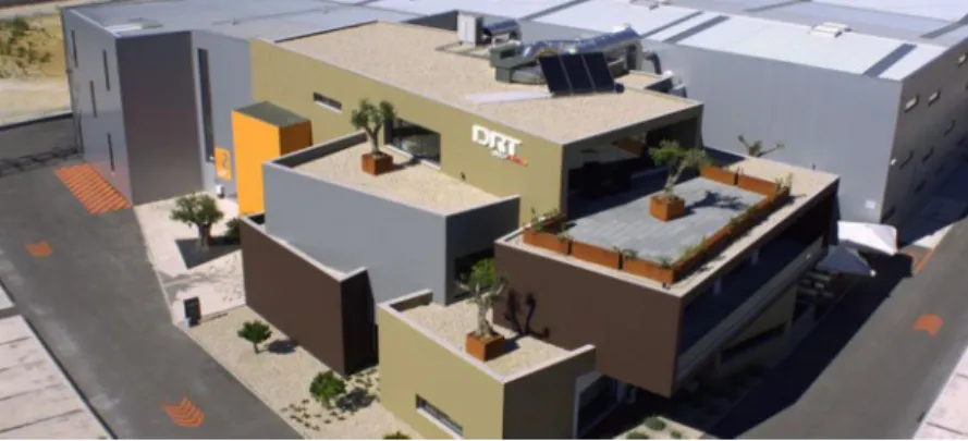
Figure 2 - New Building DRT (DRT Moldes, 2012)
This opening allowed DRT to employ more workers and vary its range of types of moulds, as the functions now played by these new
3 facilities has provided the creation, design and engineering and tool management, thus being able to compete with the "big” international market.
An investment of about 12 million euros was made that did strengthen the position of ESRD in this market sector, thus making an increase in production as well as increasing exports
At the moment, the DRT has approximately 120 employees and currently exports to Germany, Russia, Spain, France, Mexico, Portugal, India, and Austria.
The new facilities are located at the address: Rua dos Marinherios, lota 6 No. 146 Industrial Area Cova das Faias- ZICOFA 2415-806 Marrazes – Leiria
DRT also have a page on the Internet at: www.drtmouldes.com
2.2 Facilities and Equipment
This is the plan and layout of the company, on the 1st floor is the part of the drawing and offices which is not visible from this plan. For easier to be appreciated:
• Benches Zone • Erosion zone • Machining Zone • Injection Zone
• Zone reception, restaurant and some meeting rooms • Warehouse zones
4
Figure 3 - Ground plan of DRT (DRT Moldes, 2012)
2.2.1 Design / Project
The drawing room is located on the 1st floor of the company, being one of the cleanest and nice place to work form the entire plant. This department is divided by designers of moulds and electrodes designers. In total, about 22 people, including four for electrode design and 18 for the mould design.
The company uses two programs, Catia V5 and Creo 3.0 for part of the moulds and the Power Shape for the design of part of the electrodes
5 2.2.2 Machining (CNC)
In this department about 20 employs and is composed of 17 CNCs for machining.
There are several types of machining centres present in this part of the company, half of them to work in small-sized pieces and do not need to have large working desks especially the 3 axes CNC. There are also some 5-axis here the table is larger and can do the mould which are larger and more complex. There is also a machining 6-axis CNC that used for drilling deep hole, one of the most impressive machines this company doing more complex jobs.
There is another CNC also quite interesting but it is only used to make holes. It also has a rotating table, but not in angle upon itself and that the drill head bears various lengths. This structure is horizontal and can make angles from the -15º and 30º and can make holes up to an incredible 2 meters.
There are other two centres of machining, but not in this department. These two machining centres, 3-axes and other axes 5 are to be inserted at the electrodes, which I will speak ahead.
In this department there is also a room dedicated to CAM which has about 7 computers equipped with the Mouldex 3D CAM programs where the people work and where the professionals who have a machining Centre in charge are also entitled to use for programming.
6 2.2.3 Erosion
This department is of those we have few workers, total 4 because there are two machines for each employee. This part consists of eight CNC machine erosion penetration, the second wire cutting machines CNC and the other wire drilling machine.
Also in this department there is a cell which includes two machining centres but to make graphite electrodes need not have a large size compared to machining centre of steel, with a 3 axis and 5 axes. It is further constituted by two warehouses which take about 180 electrodes, a robot that transports electrodes for warehouses electrode and a measuring machine.
There is also a compartment near the cell that is where you prepare the graphite making the cut and fixation. This department consists of an electric saw, a press and a manual milling machine.
7 2.2.4 Bench
Part of the bench may be one of the Interesting areas and busy, all the time because this part is where we begin to assembly the mould. This department has about 20 people.
It comprises about work, each equipped with essentially tools for adjustment and assembly of moulds.
There is a press that this department reaches the 2,000 tons of clamping force, a central polishing which comprises an isolated room if any dust that may arise on the part of the stands, this being equipped with specific materials and light enough to better see mordant the finish area. There is also a room for the laser welding isolated visually as its light is very harm to view. Although the bench is part of warehouse with everything one needs to work along the lines as sandpaper until the number 1200, paints, hundreds of settings screws, drills, electrical parts, etc.
8 2.2.5 Injection
Injection moulding moulds and high pressure die casting dies are fabricated to a standard mould set. The standard mould set consists of two clamp plates, two cavity plates, guiding elements between them, an optional back plate, two risers and an ejector set. Ejector set consists of an ejector base plate, an ejector retaining plate and an optional set of buffer plates. Guiding elements are guide pillars, guide sleeves and centring sleeves in each corner of the mould.
This injection moulding process may be used for production in large quantities and pieces of many different sizes. The material of choice is melted and injected under pressure into a mould, and the area of the cavity that will determine the shape that is intended in the final part. The injection moulding process is considered by many ways the best choice for economically producing a large scale, but nevertheless the material cost is often significant.
The cycle of a mould during injection moulding is as follows: a) Mould Closing
b) Injection advance unit
c) Injection of plastic material into the mould
d) Cooling the mould and consequently the moulded part e) Opening the mould
f) Advancement of extractors
9 2.2.6 Integration in company
Integration in the DRT was good. Even before starting the Internship I knew two workers of this company who gave me good references. The day I started the Internship, on 12 March, the Chief decided that I should begin in the area of the CNC. I was then Left with Mr. Pedro, one of CNC worker of the most experienced and knowledgeable of what he do. Over 3 month I was in the same department and I was transferred to the drawing area, where I stayed about two weeks in charge of Mr. José Gabriel, a man with good sense of humour and that helped me to interact with other employees of this department. The next step was to understand about the electrode design, but this has not happened since I was referred to the cell.
Both in part from the stands, drawing and erosion people were friendly and available.
In short, since the beginning of the Internship to its end I felt integrated because the environment has always been good.
2.2.7 Design
As had been said earlier, this drawing room is divided by designers of moulds and electrodes designers. On the first day I went to a mould designer, Mr. José Gabriel was already working on a template with him for a few months.
What is CAD? The CAD, being an English acronym which translated means Aided Design or Computer Aided Design, is a generic name that is attributed techniques used to produce technical drawings and is used in a series of areas.
This type of program has tools for constructing different geometric shapes and three-dimensional shapes.
The company uses two programs, Catia V5 and creo 3.0 for part of the moulds and the Power Shape for the design of part of the electrodes.
10
Figure 9 - Designing Room (DRT Moldes, 2012)
I saw that there was a planning of the moulds where such was visible: • Preliminary + Mould flow Delivery
• Preliminary Approval + Mould flow / delivery of the list of materials • 3D models of Delivery + beginning of Milling
• Home Erosion
• Structures Delivery Systems • Home of the bench
The times varied depending on the size and complexity of the mould. I noticed that it is then a work order for everything to be done as quickly and as well economic. At first, the client sends the piece that he want to be made that may already be a part produced by another cast, or if a new piece in digital format. The play is studied to know where you have to take the balances, extractors, if you need furniture elements, etc. It then made a preliminary that is sent to the customer to give his approval. Once approved, it is possible to order some of the plates, well ahead already quite work, I noticed that the designers have permanent contact with the schemers cutting steel for any changes that may be made must be communicated before the job is done. I realized also that the designer has to be in touch with the customer to say at what stage will the mould and even if the designer find a problem has to ask if the piece itself can be changed a few millimetres, for example to get the balance work perfectly. This same thing happened while I was with this gentleman and the customer left to be done these changes without any problem., As I was not allowed
11 to use the company's software because it could unintentionally modify or delete important things was using the well-known CAD program Solid Edge, a program that I have installed on your computer while attending the course, I was trying to keep up while Mr. Joseph, plates slide and mobile elements, This is a different work area from any other because it would use much the head instead of force, In the database that had already had stored some parts such as buffers, records, all kinds of screws, etc. So it's easier for how some parts are already made is not lost so much time drawing. When I realized, since the two weeks had passed and it was then time to move to the electrode design section. This section, which is on the same drawing room had only three hours, long enough for me to pass the program using the Power Shape and start trying to make shapes of the electrodes from measures invented by me.
2.2.8 Other
This category of "other" is part of some machines that do not fit into any of the above said categories, but all are interconnected because deep down they are all necessary, some more use and importance than others but all with its value.
In this category are the 4 injection machines that the company has, all with different characteristics can be tested mould varied much physical characteristics such as types of plastics and injection forces. There are also scattered by the various sheds five grinders manuals, a rectifier automatic, plus two manual milling machines used more to less rigorous work as feet for the moulds, also has two lathes, a manual and other CNC. Chain saws for cutting steel, an apparatus for exchanging mills by heating the cones and immense bridges for carrying the moulds and their components. The maximum load for the strongest bridge that there is 35 tons, but there are more in quantity can only carry up to 5 tons
12
13
3.
Subtractive Manufacturing and Additive
Manufacturing
Machining is any of various processes in which a piece of raw material is cut into a desired final shape and size by a controlled material-removal process. The processes that have this common theme, controlled material removal, are today collectively known as subtractive manufacturing, in distinction from processes of controlled material addition, which are known as additive manufacturing. Exactly what the "controlled" part of the definition implies can vary, but it almost always implies the use of machine tools (in addition to just power tools and hand tools).
Additive Manufacturing (AM) is defined by the American Society of Testing and Materials (ASTM) as “the process of joining materials to make objects from 3D model data, usually layer upon layer, as opposed to subtractive manufacturing, methodologies, such as traditional machining” AM methods differ from subtractive methods, such as milling or turning, by the intuitive concept that the part is being created by the incremental addition of material. Common industry names for the AM methods are: freeform fabrication, additive processes, layered manufacturing (LM), additive techniques, and additive layer manufacturing (ALM).Currently, there are seven ALM processes with the following normalized names adopted by ASTM International Committee F42 on Additive Manufacturing Technologies: Vat Photo polymerization process (commercially known as stereo lithographic), Material Jetting (ink jet printing), Binder Jetting (3d printing), Material Extrusion (fused deposition modelling), Sheet Lamination (laminated object manufacturing), Direct Energy Deposition (laser engineered net shaping), and Powder Bed Fusion [selective laser sintering (SLS), selective laser melting (SLM) , electron beam melting (EBM), direct metal manufacturing, and direct metal laser sintering (DMLS)].
14
3.1 Additive Manufacturing v/s Subtractive
Manufacturing
Both additive and subtractive manufacturing methods have their own advantages which makes them appropriate for different circumstances a brief comparison is presented.
Speed
Additive manufacturing such as done by of complex parts with a lower lead time than CNC machining. Other than production lead time, once you submit and loading your choice of thermoplastic material, no specific tooling or setup is needed. This allows you the freedom and responsiveness to shorten your prototype, development and production cycle. CNC machining requires tooling set-up and initial programming for geometries of new parts. Both additive and subtractive manufacturing require the relevant process lead-time to schedule your task.
Complexity
In DMLS manufacturing parts with complex geometry directly from your CAD files. Because of the deposition process, where material is built up in layers, central hollows and voids and internal structure are possible with high tolerance with DMLS that might not be possible with CNC machining, as DMLS builds up the product from layers of applied material. With CNC machining, some complex internal structures are not possible as there is no access for the machine tool. Customization
Both CNC and 3D processes allow a range of parts customization. However due to the mentioned shorter setup and complex capability, 3D can manufacture individually customized parts such as medical devices which are also intended for long duration use. Five-axis CNC machines also routinely are used to produce individual dental products
15 Material
DMLS uses a range of polymer materials including ABS, Polycarbonate, and PC/ABS, which combines light weight with high strength. CNC machining can use both polymers (such as Delrin) and a wide range of metals including aluminum, titanium, magnesium, brass and stainless and HC steels and exotic metals and alloys. Function
While some of the materials used above are used by both processes, the function and or specifications of the end product may dictate the choice of material. Each process can lend itself to contrasting end use. Product from a subtractive process is usually somewhat more suitable for long duration use. However its shorter lead time makes FDM suitable for checking fit or for producing presentation and external design models though some of the products of 3D printing are long lifetime personalized products used in the medical and dental industries.
Size and Finish
Fused Deposition Modelling allows finished product sizes of up to 900 cubic cm. CNC subtractive machining can manufacture parts of up to a cubic meter square with even longer lengths possible. While 3D printing can achieve various levels of tolerance for the most accurate results, CNC machining is capable of achieving more accurate tolerances and cosmetic and surface finishes across a higher volume of parts
Part Quantity
Additive manufacturing is well suited to single or small numbers of items manufacture, when the material, tolerance and finish aspects are already considered and setup time is eliminated. Subtractive CNC machining requires longer setup and programming time and operator skill. However once prototyping has been completed using additive processes, and if you are moving to larger volumes you would likely then consider moving to a more cost effective subtractive process.
16 Hybrid Processing
As we have both capability in both additive and subtractive, we can apply the flexibility of additive with the accuracy & finish of subtractive techniques. This means that we can manufacture products with previously unachievable geometry and introduce high precision features in hybrid operations.
17
4. CNC
Computer Numerical Control (CNC) is a specialized and versatile form of Soft automation and its applications cover many kinds, although it was initially developed to control the motion and operation of machine tools.
Computer Numerical Control may be considered to be a means of operating a machine through the use of discrete numerical values fed into the machine, where the required 'input' technical information is stored on a kind of input media such as floppy disk, hard disk, CD ROM, DVD, USB flash drive, or RAM card etc. The machine follows a predetermined sequence of machining operations at the Predetermined speeds necessary to produce a work piece of the right shape and size and thus according to completely predictable results. A different product can be produced through reprogramming and a low-quantity production run of different products is justified.
Numerical Control: NC is the operation of M/c tool by a series of coded instructions consisting of numbers, letters of the alphabets and symbols, which the MCU (Machine Control Unit) can understand. Computer Numerically Controlled: When numerical control is performed under computer supervision, it is called computer numerical control (CNC). Computers are the control units of CNC machines. A programmer enters some information in the program, but the computer calculates all necessary data to get the job done. For both NC and CNC systems, working principles are the same. Only the way in which the execution is controlled is different. Normally, new systems are faster, more powerful, and more versatile.
18
Figure 11 - CNC Machine (DRT Moldes, 2012)
4.1. Working Principles of CNC Machine
CNC is computerized technology by controlling the relative movements between the tool and the work piece geometrical shapes are machined. Control of these relative movements through coded letters numbers is known as Numerical Control of machine tools. NC is simply a way of electronically controlling the operations of a machine. In conventional machine operator directly controlling the machine functions. Where as in NC machine a separate media which is in between machine and operator is controlling the machine functions. These NC machines do not have any memory of their own and hence capable of only executing a simple block of information fed to it at a time. Hardware automation gave way to computer controlled automation in manufacturing process. Computer numerical control is the term used when the control system of an NC includes a computer. The availability of a dedicated computer permits new control features to be made available on CNC machines.
19
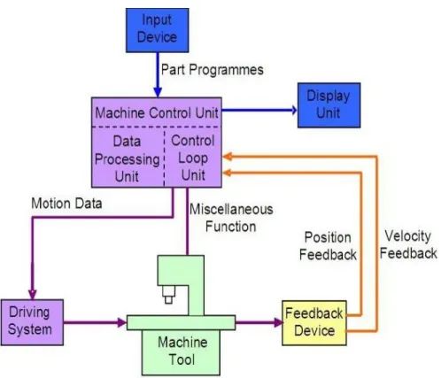
Figure 12 - Working Principle of CNC Machine (Nanfara, Uccello, & Murphy, 1995)
4.2. Control Systems
Open Loop Systems: Open loop systems have no access to the real time data about the performance of the system and therefore no immediate corrective action can be taken in case of system disturbance. This system is normally applied only to the case where the output is almost constant and predictable. Therefore, an open loop system is Unlikely to be used to control machine tools since the cutting force and loading of a machine tool is never a constant. The only exception is the wire cut machine for which some machine tool builders still prefer to use an open loop system because there is virtually no cutting force in wire cut machining.
20
Figure 13 - Block diagram of open loop system (Nanfara, Uccello, & Murphy, 1995)
Close Loop Systems: In a close loop system, feedback devices closely monitor the output and any disturbance will be corrected in the first instance. Therefore high system accuracy is achievable. This system is more powerful than the open loop system and can be applied to the case where the output is subjected to frequent change. Nowadays, almost all CNC machines use this control system.
Figure 14 - Block diagram of Close loop system (Nanfara, Uccello, & Murphy, 1995)
4.3. Elements of CNC Machine
A CNC system consists of the following 6 major elements: a. Input Devices
b. Machine Control Unit c. Machine Tool
d. Driving System e. Feedback Devices f. Display Unit
21 4.3.1 Input Devices
Floppy Disk Drive: Floppy disk is a small magnetic storage device for CNC
data input.
USB Flash Drive: A USB flash drive is a removable and rewritable portable hard drive with compact size and bigger storage size than a floppy disk
Serial communication: The data transfer between a computer and a CNC machine tool is often accomplished through a serial communication port.
Ethernet communication: Due to the advancement of the computer technology and the drastic reduction the cost of the computer, it is becoming more practical and economic to transfer Part programmes between computers and CNC machines via an Ethernet Communication cable. This media provides a more efficient and reliable means in part programme transmission and storage.
4.3.2 Machine Control Unit (MCU): The machine control unit is the heart of the CNC system. There are two sub-units in the machine control unit: the Data Processing Unit (DPU) and the Control Loop Unit (CLU).
Control Loop Unit: The data from the DPU are converted into electrical signals in the CLU to control the driving system to perform the required motions. Other functions such as machine spindle ON/OFF, coolant ON/OFF, tool clamp ON/OFF are also controlled by this unit according to the internal machine code
4.3.3. Machine Tool: This can be any type of machine tool or equipment. In order to obtain high Accuracy and repeatability, the design and make of the machine slide and the Driving lead screw of a CNC machine is of vital importance. The slides are usually machined to high accuracy and coated with anti-friction material such as PTFE and Turcite in order to reduce the stick and slip phenomenon. Large diameter Recirculating ball screws are employed to eliminate the backlash and lost motion. Other design features such as rigid and heavy machine structure; short machine table overhang, quick change
22 tooling system, etc. also contribute to the high accuracy and high repeatability of CNC machines.
(a) (b)
Figure 15 - (a) Ball Screw in CNC Machine, (b) Ball Screw Structure (Manuf., 2007) 4.3.4 Driving Systems: The driving system is an important component of a CNC machine as the accuracy and repeatability depend very much on the characteristics and performance of the driving system. The requirement is that the driving system has to response accurately according to the programmed instructions. This system usually uses electric motors although hydraulic motors are sometimes used for large machine tools. The motor is coupled either directly or through a gear box to the machine lead screw to moves the machine slide or the spindle. Three types of electrical motors are commonly used they are DC Servo motor, AC Servo motor,Stepping motor
4.3.5 Feedback Device: In order to have a CNC machine operating accurately, the positional values and speed of the axes need to be constantly updated. Two types of feedback devices Are normally used, positional feedback device and velocity feedback device. Positional Feed Back Devices: There are two types of positional feedback devices: linear transducer for direct positional measurement and rotary encoder for angular or indirect linear measurement. Linear Transducers - A linear transducer is a device mounted on the machine table to measure the actual displacement of the slide in such a way that backlash of screws; motors, etc. would not cause any error in the feedback data.
23
Figure 16 - Linear Transducer (Courtesy of Hidenhain) (Manuf., 2007)
Rotary Encoders - A rotary encoder is a device mounted at the end of the motor shaft or screw to measure the angular displacement. This device cannot measure linear displacement directly so that error may occur due to the backlash of screw and motor etc
Figure 17 - Incremental and Absolute Rotary Encoder (Manuf., 2007)
Velocity Feedback Device: The actual speed of the motor can be measured in terms of voltage generated from a tachometer mounted at the end of the motor shaft. DC tachometer is essentially a small generator that produces an output voltage proportional to the speed.
24 4.3.6 Display Unit: The Display Unit serves as an interactive device between the machine and the operator.
Figure 19 - Display Unit for CNC machine (Courtesy of Heidenhai) (DRT Moldes, 2012)
4.4 IMPORTANT TERMS RELATED TO CNC
MACHINING
Machine Zero - Machine zero is a point at the origin of the machine’s coordinate measuring system. All the Axis movements and other dimensions are measured from this point. It is similar to the origin of coordinate measuring system.
Machine reference point - It refers to the initial point of return for the purpose of measuring/feedback systems. Whenever a CNC machine is switched on the feedback system has to be initialized by referring this point on every axis.
Work Zero - This is the origin for the measuring of dimensions of work piece. The programmer is free to select it anywhere on the drawing.
Absolute measuring system - In this measuring system all the dimensions are made from the work zero, which defined. The machine
25 control uses work zero as the reference point to position the tool during program execution. The main advantage of programming in absolute system is that any point can be readily changed without affecting subsequent dimensions.
Incremental measuring system - The movements are based on the change in position between two successive points. It expresses the relative distance between the current location and the next position. This type of measuring system is called Incremental Measuring system. The main advantage of this system is that sum of the dimensions must always be zero if start point and finishing point is same at the end of programming which makes it easy to check a program.
Axis designation (conventions) - Axis designation for each type of machine tool is suggested in the EIA (Electronic Industries Association) RS 274-B standard. This conforms to ISO Recommendations R831. The nomenclature of the three main axes (X, Y AND Z) is based on the “Left hand rule”. The thumb indicates the orientation of the X-axis; the index finger indicates the Y-Axis, and the middle finger points in the direction of the Z-axis.
Spindle speed - The spindle speed is the rotational frequency of the spindle of the machine, measured in revolutions per minute (RPM). The preferred speed is determined based on the material being cut. Using the correct spindle speed for the material and tools will greatly affect tool life and the quality of the surface finish.
Feed rate - Feed rate is the velocity at which the cutter is fed, that is, advanced against the work piece. It is expressed in units of distance per revolution for turning and boring (millimeters per revolution). For milling it is expressed in units of distance per time for milling (millimeters per minute).
Cutting Speed - Cutting speed may be defined as the rate (or speed) that the material moves past the cutting edge of the tool, irrespective of the machining operation used — the surface speed.
26 4.5 CASE STUDY ON WALL THICKNESS
Product wall thickness is a key consideration when designing products for plastic injection molding. Thicker walls will offer more strength, but they are also more likely to suffer from warping as the plastic cools in the mold. Engineers and designers are usually more focused on pushing the boundaries in the other direction, and using the minimum wall thickness for injection molding they can get away with. When mass-producing plastic parts there are a number of advantages to keeping them thin and light, and the longer the production run, the more significant these benefits become:
• Thinner parts require less material, reducing material costs
• Thinner parts cool quicker, thereby shortening the molding cycle and
reducing unit costs
• Thinner parts weigh less, potentially reducing shipping costs
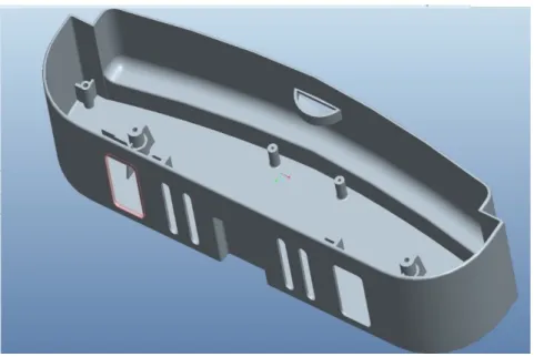
Figure 20 - Sample tool (DRT Moldes, 2012)
Cost savings are highest when components have a minimum wall thickness, as long as that thickness is consistent with the part’s function and meets all mold filling considerations. As would be expected, parts cool faster with thin wall thicknesses, which means
27 that cycle times are shorter, resulting in more parts per hour. Further, thin parts weigh less, using less plastic per part. On average, the wall thickness of an injection molded part ranges from 2mm to 4mm (.080 inch to .160 inch). Thin wall injection molding can produce walls as thin as .05mm (.020 inch).
Considerations
Generally, minimum wall thickness for injection molding is dictated by strength and the structural requirements of the product or component. We’ve also got to take the flow behavior of the material into account, as there is a direct relationship between the maximum achievable flow length for a given wall thickness and injection pressure. In both cases modern structural and flow analysis software will assist engineers in selecting the optimal wall thickness.
Just to add another variable into the mix, we can also use different types of plastics that have different strength and cooling properties! However, as a rule, the minimum wall thickness for conventional injection molding is 0.3mm, and even then it depends on the characteristic of the part itself. Below this it is unlikely we would be able to guarantee the results.
Design Advice
From a molding perspective, it’s good practice to keep wall thicknesses as uniform as possible. This is because thinner walls cool (and therefore shrink) quicker than the thicker walls, which can cause warping to occur and result in internal stresses in the product, definitely what you don’t want when you’re pushing the boundaries of wall thickness! When design considerations dictate that a uniform wall thickness is not possible, then the change in thickness should be as gradual as possible to avoid stress concentrations and abrupt cooling differences.
28
Figure 21 - Abrupt Transitions from Thin to Thick (DRT Moldes, 2012)
It´s inevitable that your parts will require some variations in wall thickness due to the incorporation of structural features such as ribs, bosses and gussets. However, the transition from thin to thick should be as gradual as possible in order to avoid mold-filling phenomena such as flow hesitation or race tracking. Given a choice, molten plastic flowing inside of an injection mold cavity will always take the path of least resistance, typically towards the thicker wall sections. Flow hesitation occurs when the melted plastic flows into a thicker section while the flow in the thinner section stalls and sometimes freezes off completely, causing major problems. Race tracking occurs when the molten plastic “races” around the edges of a part due to thicker wall sections around the perimeter of the part compared to the interior wall sections. Maintaining gradual transitions from thin to thick– as seen in the diagram–can help reduce these phenomena or eliminate them altogether, resulting in higher-quality molded parts with fewer manufacturing defects.
Rib Design
Ribs are commonly used in plastic parts to provide structural integrity, prevent part warpage and aid in the integration of internal components. However, if ribs are not designed properly relative to the surfaces they’re attached to, problems such as sink marks, warpage
29 and part failure can occur. The following rib design guidelines work well for most plastics materials:
Figure 22 - Rib Design (DRT Moldes, 2012)
• Rib thickness at the base should be between 50-70% of the
nominal wall thickness.
• Rib height should be 2.5 – 3X the nominal wall thickness. • Ribs should have 0.5 – 1.5 degrees of draft (for ejection).
• Rib base radii should be 0.25 – 0.4X the nominal wall thickness. • The distance between two ribs should be 2 – 3X the nominal
30
Figure 23 - Avoiding Sharp Corners (DRT Moldes, 2012)
Sharp corners in plastics parts act as stress concentrators that can lead to crazing, cracking, increased susceptibility to chemical attack and ultimately, part failure – so it’s a really good idea to avoid them at all costs. The good news, it’s usually pretty easy to add fillets or chamfers to avoid sharp corners altogether as can be seen in this diagram.
31
5. EDM
Electric discharge machining, sometimes also known as spark machining, spark eroding ,burning, die sinking, wire burning (or) wire erosion is a manufacturing process whereby a desired shape is obtained using electrical discharges (sparks). Material is removed from the work piece by a series of rapidly recurring current discharges between two electrodes, separated by a dielectric liquid and subject to an electric voltage. One of the electrodes is called the tool-electrode, or simply the "tool" or "electrode", while the other is called the work piece-electrode, or "work piece".
When the distance between the two electrodes is reduced, the intensity of the electric field in the volume between the electrodes becomes greater than the strength of the dielectric (at least in some point(s)), which breaks, allowing current to flow between the two electrodes. This phenomenon is the same as the breakdown of a capacitor (condenser). As a result, material is removed from both electrodes. Once the current stops (or is stopped, depending on the type of generator), new liquid dielectric is usually conveyed into the inter-electrode volume, enabling the solid particles (debris) to be carried away and the insulating properties of the dielectric to be restored. Adding new liquid dielectric in the inter-electrode volume is commonly referred to as "flushing". Also, after a current flow, the potential between the electrodes is restored to what it was before the breakdown, so that a new liquid dielectric breakdown can occur.
Two types of erosion are used in DRT: 1. Erosion with wire
2. Erosion with penetration
5.1. Erosion with Wire
In wire electric discharge machining (WEDM), also known as wire cut EDM or wire cutting, a thin single-strand metal wire, usually brass, is fed through the work piece, submerged in a tank of dielectric fluid, typically deionized water. Wire-cut EDM is typically used to cut plates as thick as 300mm and to make punches, tools, and dies from
32
hard metals that are difficult to machine with other methods. The wire, which is constantly fed from a spool, is held between upper and lower diamond guides. The guides, usually CNC-controlled, move in the x– y plane. On most machines, the upper guide can also move independently in the z–u–v axis, giving rise to the ability to cut tapered and transitioning shapes (circle on the bottom, square at the top for example). The upper guide can control axis movements in x–y–u–v– I–j–k–l. This allows the wire-cut EDM to be programmed to cut very intricate and delicate shapes. The upper and lower diamond guides are usually accurate to 0.004 mm, and can have a cutting path or kerf as small as 0.021 mm using Ø 0.02 mm wire, though the average cutting kerf that achieves the best economic cost and machining time is 0.335 mm using Ø 0.25 brass wire. The reason that the cutting width is greater than the width of the wire is because sparking occurs from the sides of the wire to the work piece, causing erosion. This "overcut" is necessary, for many applications it is adequately predictable and therefore can be compensated for (for instance in micro-EDM this is not often the case). Spools of wire are long — an 8 kg spool of 0.25 mm wire is just over 19 kilometres in length. Wire diameter can be as small as 20 micrometres and the geometry precision is not far from +/- 1 micrometre. The wire-cut process uses water as its dielectric fluid, controlling its resistivity and other electrical properties with filters and de-ionizer units. The water flushes the cut debris away from the cutting zone. Flushing is an important factor in determining the maximum feed rate for a given material thickness. Along with tighter tolerances, multi axis EDM wire-cutting machining centres have added features such as multi heads for cutting two parts at the same time, controls for preventing wire breakage, automatic self-threading features in case of wire breakage, and programmable machining strategies to optimize the operation. Wire-cutting EDM is commonly used when low residual stresses are desired, because it does not require high cutting forces for removal of material. If the energy/power per pulse is relatively low (as in finishing operations), little change in the mechanical properties of a material is expected due to these low residual stresses, although material that hasn't been stress-relieved can distort in the machining
33
process. The work piece may undergo a significant thermal cycle, its severity depending on the technological parameters used. Such thermal cycles may cause formation of a recast layer on the part and residual tensile stresses on the work piece. If machining takes place after heat treatment, dimensional accuracy will not be affected by heat treat distortion.
Figure 24 - CNC Wire Cut EDM Machine (DRT Moldes, 2012)
After erode the machine is tested with the same zone through proper tools to whether the measure is correct, to ascertain whether it is necessary to remove more material or not
34
5.2. Erosion with Penetration
It is done by using a graphite electrode or copper, having been made the study of which is done in eroded area. It focuses on the hole / box or another place to start to erode. The head of the machine already set with the electrode and already in place makes orbits while eroding and the electrode to erode the steel waste, a type of sludge that will be filtered later. The electrode is not in contact into with the material being always at a certain distance in both x and z what is termed GAP. the piece is covered by a dielectric liquid and how ever the graphite is an excellent conductor of electric shock, this upon contact, the graphite begins to erode as the machine launches electric shocks to make it possible to do the required work. In this type of erosion there is a VDI scale where the roughness values by / levels is presented, it is possible to obtain the desired roughness
Figure 26 - Erosion with Penetration(DRT Moldes, 2012)
5.2.1. Erosion with Dielectric: Every experienced, expert knows that the flushing process is of utmost importance, when metals are
35 subjected to this procedure. The dielectric must flush away the eroded particles from the gap between electrode and work piece, otherwise they may form bridges, which cause short circuits. Such arcs can burn big holes in the work piece and in the electrode. Modern spark erosion plants therefore have a built in power adaptive control system, which increases pulse spacing as soon as this happens and reduces or shuts off the power supply completely. The more thin-bodied a dielectric and the lower its surface tension, the better it is able to meet flushing requirements.
Figure 27 - Erosion with Dielectric (DRT Moldes, 2012)
Figure 28 - To get better understanding how these is developed is explained in Erode 3-boxes (DRT Moldes, 2012)
36
Figure 29 - Cell (DRT Moldes, 2012)
It all starts by designers in the upstairs to they bring A4 sheets indicating the graphite measurements in the rough, kind of graphite, type of rod to use, time it takes the precession machining, observations, quantity, you have mirrors and in X or Y, the value of GAP so that the machine is intended (3x, 3x or 5x / 5), developer name and identification electrode by mould piece and electrode number are included in the above sheet
After receiving this sheet we will search to see, if there would be material required for action if it were not found, would have to fill out an internal request for an order of graphite was done with the right measures.
37 After the graphite arrived measurement are taken. The measurements are taken in the x, y, and z axes for e.g. (455x150x122 mm.)
After placing the graphite comes on top of the sheet to which it belongs has to go looking for kind of stems that are described in the sent sheet. In total there are 10 types of rods as shown in the following table.
Table 1 - Types of Stems
50×50 R20
Normally used / Can be used on the robot 50×50
PL
Normally used / Can be used on the robot 25×25
EW
Normally used / Can be used on the robot 15×15
EW
Normally used / Can be used on the robot 50×100
PL
Not much used / Inserted by hand 100×150
PL
Not much used / Inserted by hand 15×15
COPPER
Not much used / Inserted by hand 15×40
COPPER
Not much used / Inserted by hand 25×25
COPPER
Not much used / Inserted by hand 25×63
COPPER
Not much used / Inserted by hand
Copper rods they are used when you want to erode something that is deeper and normal stems that outwardly has 50x50x50 and hit the
38 piece. Another solution was to make the much longer electrode but then there would be problems both in the same machining as the erosion process to be so fragile.
Figure 30 –Graphite rod (DRT Moldes, 2012)
After arrange the types of applications in paper, rod has to proceed to the cleaning of the faces of the graphite z using a manual cutter. The graphite is then smoothed on one side to the rod to be placed perpendicular to the graphite. After the parts cleaned on one side they are separated and the manual milling cutter is replaced by a drill 6, 8 or 10mm depending on the type of stem which is desired.
After the parts are removed it is time to find your centre to carry out drilling to hold the rod in graphite. When we drill in the exact centre of the piece walked x 18 or 20 mm depending on the rod and make a hole about 20 mm in depth. After all the parts are properly pierced has to be made will thread cutting with a machine that is in the zone of the stands. Having made the thread is time to tighten the rod to graphite. These raw electrodes are measured by a meter gauge and
39 then have to take 1 mm to make sure that cleans well. This value is recorded on the sheet and then also be seen by erosion staff. After labels are taken.
It carries a rod to be identified with the mould number, electrode number, whether it is right or mirror and mirror in x or y, GAP and height z. Then a chip is placed on the rod and it's all arranged on the side of the cell to the table. Imagining we have 6 electrodes to place. We get the 6 electrodes and the sheet and check if the data on the labels will correspond sheet that accompanies them. Then it is checked whether all screws are tight, and the same with the chip. Then you create a folder where you put the number of the mould and start. To that folder is imported the program you want and you need to pay attention to see to that machine are directed those electrodes. After imported the programs of electrodes right and left have to edit and change for each of the 3 number electrodes. So when you open one of the programs appear three rectangles the pale pink-violet colour, which means that nothing has yet been registered
Electrodes have to separate the rights of left and we recording the pre-set each chip compared the label. Deep down you do it assign a program to each chip and each stem has a chip. In this case we assign a program equal to 3 chips that were equivalent to the right electrode of the program and we assign another program like other 3 chips that amounted to the left electrode program.
After all prepared and registered it's time to put these electrodes in one of the cell warehouses.
After put in place, close the door of the warehouse and wheel, causing the chips to go through sensors. The positions are all present on a monitor and those that are green is because they are ready to be machined and which are pale pink-violet colour are those just put and was still nothing changed, so have these six rectangles that we have to put the priority we want depending on their urgency.
40
Figure 31 - Electrodes measuring machine (DRT Moldes, 2012)
Supposedly the electrodes after machined should be measured with an own machine that measures to the thousandth before being taken but that does not happen because there is so much work and so little time. What is usually done often in the case of having many electrodes with the same program is to try one to see do well, then at night when it gets to do yourself no problem because it has a well while we were present, to be sure that next they also do will do well without us playing so safe and there is no danger of the machine stop in the middle of the night with problems because of machining.
41 At the end of one electrode machining, the robot will pick you up and puts in place where fetched, then grabs the next that have the highest priority and puts the machine from which it takes earlier. When seem the pieces and if they are urgent are immediately taken to the foot of the erosion machines for use but when there is nothing pressing to do fill up boxes that take up to 12 electrodes and are put for later use. The cell always needs some maintenance and inventory records.
There are always three steps that have to do when you arrive in the morning:
- Remove the warehouse electrodes that are ready; - Clean the cabins of CNCs;
- Check times of tools
There are about 30 different tools on each machine as we can see by this list:
42 When they reached the 1100 minutes, the tools are taken and can be seen the glow at the tip meaning that the diamond bath is out. So it takes the cone with the cutter and will be sought a new mill. There is a machine that heats the cone and that they have to choose the correct heating program for the type of cone and open enough to be able to take the old mill and the other having already prepared will is so far down.
Figure 34 - Thermal heating machine for changes rotary burrs (DRT Moldes, 2012)
Figure 35 - CNCroulette 3X (DRT Moldes, 2012)
Parts made in a plastic injection moulding process can have their own unique set of possible defects. The following is one of the most
43 common defects associated with the plastic injection process in which I worked on
5.3 Case study: Feasibility Study on Draft angle
Draft angles are needed so that a plastic part can be released from the mould without distortion or damage. The high pressures of injection moulding force the plastic to touch all the surfaces of a mould’s cores and cavities. The cavity becomes so tightly packed that it is often difficult to remove the part. Sometimes, shrinkage will actually make it easier to take the part out of the mould, but in other cases, shrinkage will cause the part to stick to the mould’s cores. These natural
occurrences call for draft angles.
44 Draft angles are needed so that a plastic part can be released from the mold without distortion or damage. The high pressures of injection molding force the plastic to touch all the surfaces of a mold's cores and cavities. The cavity becomes so tightly packed that it is often difficult to remove the part. Sometimes, shrinkage will actually make it easier to take the part out of the mold, but in other cases, shrinkage will cause the part to stick to the mold's cores. These natural occurrences call for draft angles. No single draft angle is suitable for all parts. Each individual part requires a unique specification. Large parts call for more draft than small parts. Thin-walled parts that undergo high-pressure injection molding need more draft than parts that are subjected to lower-pressure molding. When calculating appropriate draft angles, the plastic material's shrinkage and physical properties are also considerations. Sizeable draft angles and smooth polish should be used for parts molded in strong, inelastic, abrasive and gluey materials. Smaller draft angles can be utilized on soft, malleable and slippery plastics.
From a cost and manufacturability viewpoint, the ideal draft angle is the largest angle that will not lessen the customer's satisfaction with the product. The minimum allowable draft angle is harder to quantify. Plastic material suppliers and molders are the authority on what is the lowest acceptable draft. In most instances, 1i per side will be sufficient, but between 2i and 5i per side would be preferable. If the design is not compatible with 1i, then allow for 0.5i on each side. Even a small draft angle, such as 0.25i, is preferable to none at all.
Draft angles must be provided for several part details. For example, the sidewalls that are perpendicular to the mold's parting line must be drafted. Other areas that require draft angles include mounting flanges, gussets, holes, hollow bosses, louvers and other holes. The location of the mold's parting line sometimes remains unknown, however. This lack of information makes it impossible to ascertain whether the part's draft angles should have positive or negative values. As a result, designers commonly draw the part without individual draft angles but with a general specification such as 'allowable draft 1°.
45
6. DMLS
It was not until the 1970’s that the first powder AM methods began to appear (Systems, 2004). In 1971, Ciraud applied for a patent on a powder AM method, which was described in the patent as "the invention makes possible the manufacture of parts which can have extremely complex shapes, without the need for casting moulds” (Systems, 2004). In the latter half of the 1970s, Householder patented the first powder laser sintering system (Systems, 2004). This sintering system was described in the patent as able "to provide a new and unique moulding process for forming three-dimensional articles in layers and which process may be controlled by modern technology such as computers” (Systems, 2004). In 1992 and 1994, the first and second commercial selective laser sintering machines were shipped: the sintersation 2000 by DTM Corporation and EOSINT (P) 350 by EOS Firm respectively (Systems, 2004). In 1995, one of the first direct metal laser sintering machines, the EOSINT M 250, was installed for commercial use (Systems, 2004). This machine allowed for the best part complexity, geometry, and surface quality to date for any direct metal laser sintering machine (Systems, 2004). In 2004, the EOSINT M 270 machine series was released, featuring a solid-state fibre laser (Systems, 2004). EOS continued to develop new and exotic models of DMLS machines, even making a precious metal machine (PRECIOUS M 080) (Cerreta, Direct Metal Laser Sintering :An Overview, 2014). In 2013, EOS released it latest and most advanced machine (EOS M 290) for the manufacturing of high performance metal components (Cerreta, Direct Metal Laser
Sintering :An Overview, 2014)
6.1. Definitions
In current literature, DMLS is defined differently by various publication authors (Bewilogua, et al., 2009), (Systems, 2004), (Sateesh, 2014, pp. 772-779) . Levy distinguished multiple metal AM methods and their processing conditions (Bewilogua, et al., 2009) and his definition of DMLS is most appropriate for the focus of this work. Levy defined DMLS as a single stage part building based on a liquid
46 phase sintering (LPS) process (Bewilogua, et al., 2009). This definition distinguishes DMLS from two similar SLS methods that produce a solid metal part, which are often mistaken for DMLS. The first method differs from DMLS in that a metal part is created by laser sintering a powdered material containing the desired metal particles, which are covered in a low melting point polymer (commonly called a “binder”), to form what is known as a “green part”. In this indirect method, only the binder is melted, which requires the use of post processing and heat treatment (usually conventional sintering in an industrial furnace) to create the final part. Similarly, the second method differs from DMLS in that a mixture of metal powders is used. One metal powder has a lower melting temperature than the other, which allows for selective melting of one metal, but commonly results in poor mechanical properties of the final part.
6.2. Mechanics
In order to understand the basic mechanics of DMLS, one must investigate the following elements of DMLS: binding mechanisms (http://www.protolabs.co.uk/additive-manufacturing, n.d.), parameters and their relationship to densifications, processing steps (Dewidar M. M., 2002), and equipment (Dewidar M. M., 2002), Rapid Prototyping.
Binding Mechanism: According to the Metal Handbook, “sintering is a thermally activated process (with or without external pressure application), whereby the powder particles are made to bond together, changing physical and mechanical properties, and developing toward a state of maximum density, i.e. zero porosity, by occurrence of atomic transport” (Cerreta, Direct Metal Laser Sintering :An Overview, 2014). Sintering is crucial to the DMLS process, and is governed by the following parameters: temperature, time, and geometry of powdered particles, composition of the powder Mix, density of the powder compact, and composition of the protective atmosphere in the sintering furnace (Dewidar M. M., 2002).
Kruth found that SLS technologies can be categorized by four binding mechanisms: solid state sintering, chemically induced binding, liquid