Repositório ISCTE-IUL
Deposited in Repositório ISCTE-IUL:
2018-04-23Deposited version:
Post-printPeer-review status of attached file:
Peer-reviewedCitation for published item:
Matos, S., Lima, E. B., Silva, J. S., Costa, J. R., Fernandes, C. A., Fonseca, N. J. G....Mosig, J. R. (2017). High gain dual-band beam-steering transmit array for Satcom terminals at Ka-band. IEEE Transactions on Antennas and Propagation. 65 (7), 3528-3539
Further information on publisher's website:
10.1109/TAP.2017.2702658Publisher's copyright statement:
This is the peer reviewed version of the following article: Matos, S., Lima, E. B., Silva, J. S., Costa, J. R., Fernandes, C. A., Fonseca, N. J. G....Mosig, J. R. (2017). High gain dual-band beam-steering transmit array for Satcom terminals at Ka-band. IEEE Transactions on Antennas and Propagation. 65 (7), 3528-3539, which has been published in final form at
https://dx.doi.org/10.1109/TAP.2017.2702658. This article may be used for non-commercial purposes in accordance with the Publisher's Terms and Conditions for self-archiving.
Use policy
Creative Commons CC BY 4.0
The full-text may be used and/or reproduced, and given to third parties in any format or medium, without prior permission or charge, for personal research or study, educational, or not-for-profit purposes provided that:
• a full bibliographic reference is made to the original source • a link is made to the metadata record in the Repository • the full-text is not changed in any way
The full-text must not be sold in any format or medium without the formal permission of the copyright holders.
Serviços de Informação e Documentação, Instituto Universitário de Lisboa (ISCTE-IUL) Av. das Forças Armadas, Edifício II, 1649-026 Lisboa Portugal
Phone: +(351) 217 903 024 | e-mail: [email protected] https://repositorio.iscte-iul.pt
Abstract—Transmit-array design is more challenging for dual-band operation than for single-dual-band, due to the independent 360º phase wrapping jumps needed at each band when large electrical length compensation is involved. This happens when aiming at large gains, typically above 25 dBi with beam scanning and F/D≤1. No such designs have been reported in the literature. A general method is presented here to reduce the complexity of dual-band transmit-arrays design, valid for arbitrarily large phase error compensation and any band ratio, using a finite number of different unit-cells. The procedure is demonstrated for two off-set transmit-array implementations operating in circular polarization at 20 GHz(Rx) and 30 GHz(Tx) for Ka-band satellite-on-the-move terminals with mechanical beam steering. An appropriate set of 30 dual-band unit-cells is developed with transmission coefficient >‒ 0.9 dB. The full-size transmit-array is characterized by full-wave simulation enabling elevation beam scanning over 0-50º with gains reaching 26 dBi at 20 GHz and 29 dBi at 30 GHz. A smaller prototype was fabricated and measured, showing a measured gain of 24 dBi at 20 GHz and 27 dBi at 30 GHz. In both cases the beam pointing direction is coincident over the two frequency bands, thus confirming the proposed design procedure.
Index Terms— Dual band, flat lens, transmit-arrays, mechanical scanning, frequency selective surface (FSS), polarization-insensitive, wireless communication network, satellite-on-the-move (SOTM).
I. INTRODUCTION
here is an intensive on-going research effort to find compact, light-weight and cost-effective antenna solutions for satellite-on-the-move (SOTM) applications [1]-[10]. The challenge is to combine these characteristics with high gain, beam-steering capability and multi-band operation. Mechanical beam steering solutions [1] are cost-effective but tend to be bulkier than their phased array counterparts [11], [12]. However, the feeding network of millimeter wave (mm-wave) phased arrays, both analog and digital, is the main limitation in terms of RF performance and cost. Reflector-based antennas are
Manuscript received July, 2016. This work is supported by the European Space Agency under contract no. 40009111/13/NL/AD and Fundação para a Ciência e a Tecnologia under the grant SFRH/BD/51925/2012 in the frame of IST-EPFL joint doctoral program.
Sérgio A. Matos, Eduardo B. Lima, Joana S. Silva, Jorge R. Costa, and Carlos A. Fernandes are with Instituto de Telecomunicações, Instituto Superior Técnico, Universidade de Lisboa, Av. Rovisco Pais 1, 1049-001 Lisboa, Portugal (phone +351-218418480 fax +351-218418472 e-mail [email protected]).
the traditional solution for mechanical beam-steering [13], but the use of reflect-arrays and transmit-arrays is becoming a new trend as they can potentially reduce the antennas’ profile and weight while maintaining high RF performance [7]-[9], [14]-[18]. In particular, frequency selective surface theory is being applied for the design of a new breed of flat Fresnel lenses or transmit-arrays [19]- [25] .
Two basic types of cell phasing mechanisms are being used: the phase-delay (PD) and phase rotation (PR) types. In PD cells the relative phase between adjacent cells is obtained through different equivalent transmission line lengths for each cell, usually associated with different effective permittivity [26], [27]; in the PR type of cells all have exactly the same geometry, the relative phase being obtained through the relative angle of in-plane rotation of the cell elements [19]-[22]. It is worth mentioning that these two types of transmit-arrays have different working principles. The PR case is exclusive for circular polarization, whereas the PD counterpart can operate with an arbitrary incident polarization.
To the best of the authors’ knowledge, the use of dual band high-gain beam-steerable antennas based on passive transmit-arrays for SOTM, using either PD or PR cells, has not yet been reported in the state-of-the-art. It may appear in a first thought that the design of a dual-band transmit-array is not fundamentally different from the single-band case, but actually dual-band transmit-arrays are more complex to design when the following conditions are verified simultaneously:
1) Need to compensate several wavelengths of phase error resulting from a very high gain requirement or low F/D (or both);
2) Unfavorable ratio between the frequency bands as explained ahead.
When several wavelengths of phase error compensation are required in single-band transmit-arrays, this can be achieved with a limited set of PD or PR cells distributed discretely between 0º and 360º, since a 360º phase wrapping can be used
Sérgio A. Matos and Jorge R. Costa are also with Instituto Universitário de Lisboa (ISCTE-IUL), Departamento de Ciências e Tecnologias da Informação, Av. das Forças Armadas, 1649-026 Lisboa, Portugal.
N.J.G. Fonseca is with Moltek Consultants Ltd for the European Space Agency, Antenna and Sub-Millimetre Wave Section, Keplerlaan 1, 2200 AG, Noordwijk, The Netherlands (e-mail: [email protected]).
Joana S. Silva and Juan R. Mosig are with Laboratory of Electromagnetics and Antennas, École Polytechnique Fédérale de Lausanne, Lausanne, Switzerland.
.
High Gain Dual-Band Beam Steering
Transmit-array for Satcom Terminals at Ka Band
Sérgio A. Matos, IEEE Member, Eduardo B. Lima, IEEE Student Member, Joana S. Silva, Jorge R.
Costa, IEEE Senior Member, Carlos A. Fernandes, IEEE Senior Member, Nelson J. G. Fonseca, IEEE
Senior Member, Juan R. Mosig, IEEE Fellow
to compensate higher phase error values although at the expense of a reduced operating bandwidth. However, the phase wrapping process can be more complicated for dual-band transmit-arrays under conditions 1) and 2). This is partly due to the independent 360º phase jumps needed at each band for each cell. Depending on the ratio between frequency bands it may lead, in large transmit-arrays, to a potentially intractable number of cells with different phase-delay pairs. Moreover, conciliating the adequate dual-band transmission coefficient phase behavior with a low transmission coefficient magnitude (at least better than ˗1 dB to constrain the back lobe reflection and favor aperture efficiency) represents another challenge.
Some dual-band cell designs with high transmissivity characteristic can be found in the literature, both of the PD [26], [27] and the PR types [28] but in most cases they do not allow setting independent phase-delay values at each band. This prevents its use for transmit-arrays, even more to handle simultaneously the implications of 1) and 2).
Recently, a first attempt to implement a dual-band planar transmit-array was presented in [29] using PR cells. However, the cells are not actually dual-band. Independent cells were designed for the upper and lower bands and were interleaved in a proper way. The cells’ amplitude response (ranging from ˗0.6 dB to ˗3.5 dB) may favor back reflection while the presented phase compensation range is small, from 0º to 229º at 20 GHz and 0º to 344º at 30 GHz without phase jumps aiming only at moderate transmit-array gain (19 dB at 20 GHz and 20 dB at 30 GHz). The interleaved cell approach is not favorable for condition 2) where spatially close phase jumps are required. Interleaved cells require more physical space than a single dual-band PD cell.
New dual-band cells with independent phase-shifting capability at each band and very high transmissivity need to be designed to respond simultaneously to 1) and 2). In this work, we present a general method for dual-band cell planning that can be used for the design of any transmit-array size, with any ratio between the design frequencies f1 and f2 of the upper and
lower bands respectively. Some rules apply for the definition of f1 and f2 to obtain a feasible design. The method allows
designing the transmit-array using only a finite set of unit-cells. It is mostly intended for PD cell design, but it is relevant for PR cells as well. The method is illustrated in this paper for two versions of a transmit-array: a full-size antenna and a slightly trimmed version for fabrication. The full-size transmit-array shows wide-angle beam-steering within the 0° − 50° interval, with gains ranging between 23 dBi and 29 dBi and circular polarization (CP). A set of 30 dual-band PD unit-cells are used for both cases, with −0.3 dB transmission coefficient magnitude on average at both frequencies (worst value is –0.9 dB) and reasonable insensitivity to polarization. In these examples, we extend for the dual-band transmit-arrays the offset phase-delay correction function used in our previous work [22] for a single-band flat lens configuration. In that work we showed that a wide beam steering range with full azimuth coverage could be obtained by combining this single-band phase correction function with both in-plane feed translation and antenna rotation Fig. 1a. The corresponding functional
prototype was presented in [30] Fig. 1b.
Full-wave simulations of both versions of the dual-band transmit-array example using CST microwave Studio® [32] have confirmed the expected dual-band performance, in line with the predefined specifications. One of the versions of the transmit-arrays was fabricated and tested experimentally at 20 GHz and 30 GHz bands. A good agreement was obtained both with the full-wave simulation results and with the specifications, confirming the practical feasibility of the proposed dual-band transmit-array design method.
This paper is organized as follows: the strategy for dual-band unit-cell design is addressed in Section II. First, a systematic method is presented to find the appropriate phase-delay combinations in each cell for a dual-band transmit-array of any size and frequency band ratio using a finite number of cells; secondly, the method is illustrated by designing an appropriate collection of dual-band unit-cells at Ka-Band (20GHz/30GHz) targeting satellite communications (Satcom) applications. Section III addresses the design and performance of a dual-band transmit-array that generalizes the previous single-band lens design developed in [22]. In Section IV we present the experimental validation of the manufactured dual-band transmit-array. Conclusions are drawn in Section V.
II. DUAL-BAND UNIT-CELLS DESIGN
A. Systematic design rules for transmit-array dual-band cells The geometry of Fig. 1a represents a generic transmit-array at the = 0 plane fed by a point source located at (0,0, − ). Throughout this paper we designate the phase term as according to the notation (note that in [22] the phase term was defined with the opposite sign).
Fig. 1 – Antenna geometry, same as in [30]
The transmit-array is intended to introduce a phase correction Φ ( , , ) to transform the input spherical wave front into an arbitrary target output wave front. We can factorize in terms of the frequency f and of a generic function of the spatial coordinates, according to
Φ ( , , ) = ℎ( , ) (1) where = 2 ⁄ is the free space wave number, being c the speed of light in vacuum, and ℎ( , ) an equivalent compensation length. Further to a physical length it can include other phase compensation conditions. It is independent of the frequency as long as the primary feed phase center position is also independent of the frequency. Consider an example where
the transmit-array is required to collimate the output beam along some zenithal direction. The equivalent compensation length at each transmit-array point ( , ) is given by [22]:
ℎ( , )= + + − (2)
When = 0, corresponding to the conventional broadside Fresnel correction, ℎ( , ) reduces to the physical length travelled by a ray from the feed phase center up to the ( , ) point of the transmit-array.
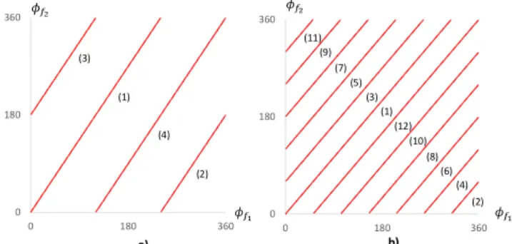
The transmit-array phase correction (1) versus ℎ( , ) for two generic operation frequencies and with > is shown in Fig. 2a. The vertical line represents the locus of an arbitrary discrete unit-cell , that is required to produce the phase delays = ( ) − ( ) where =
, is a phase reference selected independently at frequencies and , respectively. Note that the operation principle of the transmit array does not depend on the chosen phase reference. This reference corresponds to the origin of the axis in the phase representation of Fig. 2a. At first, it may seem that when considering independent 360º phase wrapping of and functions, this may lead to an intractable number of possible phase combinations defining each and every cell across the transmit-array. However, it is noted that a unit-cell can be univocally defined by the phase-pair = ( , ) where
= (3)
We can interpret the transmit-array phase compensation law as the line represented in the , plane in Fig. 2b. In this representation, any unit-cell is univocally defined as a single-point in the line segment, with the distance to the origin being proportional to the corresponding equivalent compensation length.
Fig. 2 – a) Required phase vs the equivalent compensation length, for two generic frequencies and considering unwrapped phase. An arbitrary
unit-cell is marked, corresponding to phase compensation values and . b) Corresponding phase-pair plane, where each cell is represented by a single
point over a tilted line with slope / .
The 360º phase periodicity can be used to re-write (3) as: + ×360° = × + ×360° (4) with , ∈ ℤ. Thus, by selecting appropriate ( , ) values, equation (4) can map any ( , ) phase-pair from the original infinite line of Fig. 2b into a point within a set of parallel finite lines with the same slope, defined in the finite 2D-space ∈
[0°, 360°[, ∈ [0°, 360°[. Onwards we refer to it as the reduced phase-pair (RPP) plane. We represent it in Fig. 3 for four examples of standard satellite dual-band frequency ratios as detailed in Table I. The values of and in Fig. 3 are selected within the downlink and uplink bandwidths, respectively. As will be discussed below, they do not correspond to the central frequency of each band but else to the closest and values that maximize their greatest common divisor (gcd). Thus, the lines in the RPP plane correspond to the locus of unrepeated cells, the line numbering indicating the sequence of cell locus for increasing ℎ( , ) values. If ℎ( , ) increases beyond the end of the last numbered line, the cell locus returns to the beginning of the first line and henceforth to the subsequent lines as needed. This means that a dual-band transmit-array with arbitrarily large ℎ( , ) values can be completely populated with a finite number of discrete phase cells. However, for a fixedphase discretization step , the number of unrepeated cells in the RPP plane increases with the number of lines
= + − 1 (5)
This justifies the abovementioned requirement to choose and that maximize . As an example, Table I shows the maximum unwrapped phase range in the RPP plane,
( ) = ×360°⁄ ( ) = ×360°⁄
(6.a) (6.b) for each of the previously presented satellite bands, as well as the corresponding = ( )/ , considering
= 36° for . We conclude that C- and Ka-bands allow the lowest , while the number of cells remains still reasonable in the other bands.
Fig. 3 – Reduced phase-pair (RPP) plane for standard fixed satellite dual-band services, where the lines’ slope is ⁄ : a) C-band and Ka-band (coincident
for the two bands); b) Ku-band and W-band (coincident for the two bands). Table I - Frequency bands for considered satellite services and corresponding information for transmit-array dual-band cell design. Number of cells assumes
ϕ = 36° for frequency BAN D DOWNLINK (GHZ) U PLINK (GHZ) F1 (GHZ ) F2 (GHZ ) GC D UNWRAP. RANGE UNWRAP. RANGE NLINES NUC C 3.7–4.2 5.925–6.425 4 6 2 0–720º 0–1080º 4 30 KU 11.7–12.2 14–14.5 12 14 2 0–2160º 0–2520º 12 70 KA 19.7–20.2 29.5–30 20 30 10 0–720º 0–1080º 4 30 V 37.5–43.5 47.2–50.2 40 50 10 0–1440º 0–1800º 8 50 W 71–76 81–86 72 84 12 0–2160º 0–2520º 12 70 0 500 1000 1500 2000 2500 0 0,02 0,04 0,06 0 200 400 600 800 1000 0 200 400 600 800 1000 ℎ ℎ( , ) 0 180 360 0 180 360 (1) (4) (2) (3) 0 180 360 0 180 360 (11) (1) (2) (4) (6) (8) (10) (12) (3) (5) (7) (9) a) b)
Besides the required relative phase delays of the cells, they must also present a good transmission in order to constrain the back lobe reflection and favor aperture efficiency of the lens. An indicative value would be | | > −1 dB. Difficulties may arise when trying to design physically viable dual-band PD cells that coincide with the referred ideal phase-pair lines (Fig. 3) that are evenly distributed along those lines, and that comply simultaneously with the minimum acceptable transmission coefficient condition. It is also of great importance that adjacent cells present similar geometry so that the local periodicity condition that is generally used to design PD cells remains approximately valid [31].
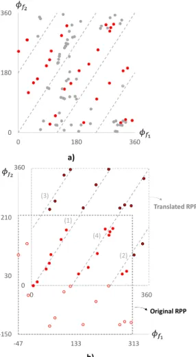
It is likely that after proper use of a ×360°, ×360° translation, or in a compact form = 360°( , ), the locus of viable cells associated to an arbitrary phase reference at each frequency = , end-up showing instead as in Fig. 4a (obtained from an example to be discussed ahead). But given that the transmit array working principle does not change with the phase reference, it is possible to adjust to provide the least error between the phase-pair locus of the developed cells and the ideal one over the lines. In the RPP representation, this corresponds to translating its origin as done in Fig. 4b: the reference phase was shifted with respect to the original one in Fig. 4a by ∆ = (47°, 150°). The uninteresting cells (gray dots in Fig. 4a) were discarded, while the remainder that fell outside the translated RPP plane (red circumferences in Fig. 4b) were recovered by proper = 360°( , ) translations (red circle with blue outline in Fig. 4b).
The above procedure is summarized as follows (Fig. 5): a) Select and within the respective bands as integer values with the maximum possible . Mark the tilted lines in the RPP plane given by (4). Select the appropriate cell configuration, set the | | criterion and set required ; b) Generate different cells by changing its parameters, analyze the respective transmission response and plot in the RPP plane those that match the | | criterion. Repeat this step until the RPP plane is well populated along parallel directions to the tilted lines (separation );
c) Adjust to obtain the best possible match between the phase-pairs locus in the RPP plane and the tilted lines and eliminate the unnecessary cells. Repeat step b) as necessary to populate the tilted lines.
Fig. 4 – a) Example of the locus of an actual collection of dual-band PD cells plotted in the reduced phase-pair plane. b) The same phase-pairs are plotted on a RPP plane that is shifted by (47°, 150°). The red circumferences that fall outside the translated RPP plane are transformed back inside by using eq. (4),
(red circle with blue outline).
c1: |s21| matches criterion (e.g. |s21|> -1 dB) c2: enough cells in RPP plane with separation c3: enough cells in RPP plane with the least error over lines
Fig. 5 ‒ Workflow for the design of dual-band cells for arbitrarily large equivalent length ℎ( , ) compensation.
B. Dual-band PD unit-cells for Ka-band
The objective of this section is to present an example of a viable set of dual-band PD cells designed according to the previous design rules. They work correctly for the previously referred transmit-array at the Satellite Ka-Band, but are not
0 180 360 0 180 360 a) 0 360 0 360 Original RPP Translated RPP b) -150 30 210 -47 133 313 (1) (3) (4) (2)
intended as the only, or the best possible dual-band PD cells. The phase delay associated with an ideal PD cell can be written as Φ = exp (− ) where ( ) is the cell’s effective refraction index and is the cell’s thickness. The relative phase presented in the previous section is thus defined as
= − − (7)
The dominant dependence of with frequency comes from , originating a negative slope behavior. An additional degree of freedom is associated with ( ), which can be explored through cell parameter adjustments.
The following steps are taken to design the unit-cells: a) Definition of the unit-cell resonant elements:
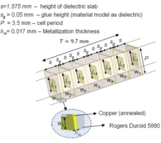
The unit-cell geometry has evolved from the design in [23], which is based on juxtaposed square patches. The periodic metallic patches behave as a low-pass filter. A strip loop is added now, centered with the patch (Fig. 6). A grid of these loops behaves as a high-pass filter. The combination of the two elements (loop plus patch) behaves as a band-pass filter with the possibility of tuning almost independently the lower and upper frequencies of the pass-band, by changing the elements dimensions. The square geometry favors similar TE and TM responses, as required for circular polarization operation.
Fig. 6 – Dual-band unit-cell configuration.
b) Definition of the unit-cell parameters:
The unit-cell size ( × ) must be large enough for its elements to resonate at the desired frequencies bands. So, the largest element, the strip loop, is intended to resonate near the lower band (Rx-band). Additionally, enough geometric degrees of freedom are required to properly populating the phase-pair map defined by the method (Figure 3). The parameters are the strip loop width , the square patch size × , the unit-cell height and the number of layers ( is the order of the metallization layer).
Parameter affects mostly the phase shift and amplitude response of the unit-cell at the lower band, while affects those characteristics mainly in the upper band. Increasing the cell height provides a wider range of phase variation, while a more diverse combination of phase pairs is obtained by increasing the
number of layers. A compromise must be found between cell performance and fabrication complexity and accuracy. c) Definition of the unit-cell population:
A full-wave analysis of an infinite periodic array of unit-cells is carried on, testing different combinations of and to reach the condition | | > −1 dB in both bands. The study is not blind, as the trends are anticipated from the behavior described in b). All the successful cells are plotted in the RPP plane and then follows the optimization of , and discarding of the unnecessary cells (those with wrong locus in the RPP plane, and abrupt geometry transition between adjacent phase cells).
Consideration of the previous steps led in our case to using seven layers ( = 1 … 7) of square metallized elements ( × = 3.5×3.5 ) printed on six substrate layers of 60 mills (s=1.575mm) Rogers Duroid 5880 ( = 2.2, tan = 0.0009), see Fig. 6. Total cell height is = 9.7 mm. The number of cell layers was determined both by the maximum required phase shift and by the maximum acceptable insertion loss. The printed layers of each unit-cell were set equal in pairs, i.e. =
, = (Fig. 6). So, each unit-cell contains only four different printed elements.
In order to define we have used known information about the influence of phase discretization error on gain degradation. A uniform discretization step of = 36° is shown in [33] to introduce 0.2 dB gain degradation compared to the continuous case → 0, for a F/D=1 Fresnel lens. For = 90° the gain reduction is almost 1 dB. In the present work, we confirmed that using in the order of 36° also represented a good compromise between the antenna performance, the feasibility to find the unit-cells with the appropriate phase pairs, and our available fabrication resolution. This translates approximately to 30 unrepeated cells in the RPP plane ( = 30, see Section II.A).
Different combinations of ∈ [0, 2.4 and ∈ [0, 0.5 were analyzed using CST microwave studio [32] with periodic boundary conditions. The unit-cells complying with the transmission coefficient condition are represented in the RPP plane (dots marked in Fig. 4a). Following the procedure described in Section II.A, the reference phase was optimized to maximize the number of dots falling near the tilted lines in the RPP plane. The thirty unit-cells that fall near these lines (red dots in the translated RPP plane in Fig. 4b) comply with the required phase at 20 GHz and 30 GHz.
Fig. 7 presents the full phase frequency response of these thirty unit-cells. The phase results are split into four different groups corresponding to four different combinations of and . The dashed line represents the cell used as the reference of the RPP plane in Fig. 4b. The insets in these figures explain the relation between the achieved absolute phase, the phase, and the equivalent phase obtained through a = 360°( , ) translation. Its correspondence in the RPP plane is marked as the red dots in the previous Fig. 4b, while its transformation into the original unwrap phase-pair plane is presented in Fig. 8. It is seen in the latter figure that the cells are reasonably distributed with an average phase step of 24º at 20 GHz and 36º at 30 GHz.
The average phase error with respect to the ideal line locus is 15º. Nevertheless, it will be shown ahead that these cells with the presented phase discretization map are just enough to obtain good dual-band transmit-array performance.
Fig. 7 – Phase responses of the designed cells vs frequency: a) Four unit-cells that cover the phase interval ϕ20GHz ∈ [0⁰, 50⁰] and ϕ30GHz ∈ [0⁰, 70⁰]; b)
Six unit-cells with ϕ20GHz ∈ [54⁰, 234⁰] and ϕ30GHz ∈ [95⁰, 360⁰]; c) 19
unit-cells with ϕ20GHz ∈ [276⁰,665⁰] and ϕ30GHz ∈ [397⁰,966⁰]; d) One unit-cell with
ϕ20GHz= 704º and ϕ30GHz=1050º.
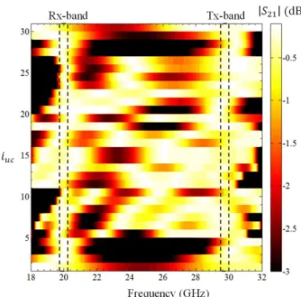
The simulated magnitude response of these thirty cells versus frequency is shown in Fig. 9. The cells present an average |S21|
of -0.24 dB at 20 GHz and -0.32 dB at 30 GHz. A good transmission coefficient is also maintained throughout the usual Ka Tx and Rx bands (shaded regions in Fig. 9): for instance, at the edges of the band the average |S21| is -0.57 dB at 19.7 GHz
and -0.38 dB at 20.2 GHz. For the lower frequency value of the Tx band (29.5 GHz) the average |S21| is 0.41 dB while it is
-0.32 dB at 30 GHz. The worst |S21| values are -0.8 dB and -0.9
dB respectively in the two bands.
Fig. 8 – Representation of the phase-pairs obtained for the designed dual band unit-cells in the phase plane [0,720° ×[0,1080° . The line segment numeric
code of the shaded regions is the same as in Fig. 7.
Fig. 9 – Transmission magnitude responses of the 30 dual-band unit-cells. The unit cells ( ) are ordered according to Table II..
III. TRANSMIT-ARRAY DESIGN
The objective of this section is to present and analyze by full-wave simulation a high-gain dual-band transmit-array with wide-angle beam steering, using the developed PD cells. Since no such transmit-arrays arrays exist in the literature to benchmark our concept, we choose the single-band transmit-array from Reference [22]. This is a case where the design was already demanding in terms of gain, beam scanning angle and circular polarization. We want to demonstrate that not only the dual-band transmit-array can match the demanding specifications of [22] for the 30 GHz up-link band, but also it offers similar performance in the 20 GHz down-link band. We then use the same beam steering principle adopted in [22] for a
0 180 360 540 720 900 1080 0 180 360 540 720 Series1 Linear (Series2) Designed cells 32⁰ 70⁰ Average error = 15⁰
106⁰ Maximum phase jump at 30 GHz Δϕ30 =1.5×∆Φ20
Maximum phase jump at 20 GHz Maximum phase error Fig. 7 d)
Fig. 7 c)
Fig. 7 b)
single-band transmit-array at 30 GHz: for the central feed position, = 0, the beam already points at direction (
Table III) with optimum phase correction given by (1) and (2). Beam steering in elevation is obtained through feed translation while beam steering in azimuth requires the rotation of the full assembly. This steering approach requires the aperture to be larger in the elevation plane to avoid spill-over. We aim at the same type of specifications as in [22], with a gain in the order of 29 dBi, wide-angle scanning in the [0, 50º] interval with scan losses below 3 dB, and F/D near 0.8 to maintain the antenna profile as low as possible.
The dual-band transmit-array is assembled as in [22], by choosing for each ( , ) position of the transmit-array the unit-cell that falls closest to the phase given by (1) and (2). It should be enough to follow this procedure for one of the bands only, since the cell design implicitly complies with the required phase lag at the other band. It is important to note that this also implies that the impact of the focal distance on the transmit-array scan angle will be the same at both frequencies, according to Eq.6 in reference [22], derived for the single-band case.
In this work we arbitrarily selected the 20 GHz band phase information for the procedure. In practice, however, an inevitable difference exists at 30 GHz between the actual cell phase response and the ideal one given by = 1.5× . The implications on the antenna response are negligible as will be quantified ahead, because the average phase error at 30 GHz is only 16º.
To facilitate the comparison between this dual-band transmit-array and the previous single-band one at 30 GHz [22], the same aperture dimensions are used: = 192.5 mm and = 143.5 mm. Also the same = 32.5° beam tilt is used for the feed central position. This choice of leads to similar level of beam distortion for the less tilted beam (15º) and the most tilted one (50º). Fig. 10 shows the top layer of the CST simulation model of the dual-band transmit-array.
Since a primary source of the type used in [22] is not available for dual band operation, two 15 dBi standard-gain rectangular horn antennas are used instead to illuminate the transmit-array at each band, with their phase centers positioned at distance from the bottom face of the transmit-array. Its focal distance is slightly changed from = 100 mm to = 110 mm, to ensure similar edge taper illumination as in [22]. The circular polarization (CP) response of the transmit-array is obtained by appropriately combining its radiation patterns obtained for two orthogonal linear polarization horn orientations [34]. This synthesized CP will onwards be referred just as RHCP (co-pol component) or LHCP (cross-pol component) both for simulations and measurements. This is different from [22] where a CP feed was used.
Despite these differences, a fair performance comparison is still possible at 30 GHz: the phase function given by (1) and (2) and the aperture illumination are practically the same in the two cases. Any performance difference will result only from the difference between the used single- and dual-band unit-cells behavior.
The full-wave CP radiation patterns are presented in Fig. 11 and the transmit-array performance parameters are summarized in
Table III. The simulation results for the single band lens from [22] are also presented in
Table III for three feed positions. The first positive indicator of this dual-band design is that the beam tilt angles are practically coincident over the two bands. This is only possible when the phase correction function is correctly implemented in both bands. The second positive indication is that the directivity and scan loss values at 30 GHz are similar to the results obtained for the 30 dBi single-band lens from [22], as shown in
Table III. In that work, the single-band results were validated by measurements. The lower gain at 20 GHz is compatible with the reduction of the aperture electrical size. Finally, the scan loss across almost 50º elevation interval is better than 3.6 dB at 20 GHz and 3.3 dB at 30 GHz.
Table II – Dimensions of each unit-cell in terms of the geometric parameters defined in the inset of Fig. 6 and ordered according to the numbering used in
Fig. 9.
Fig. 10 – Dimensions of the simulated and fabricated transmit-arrays (top layer).
The results in Fig. 11 show that cross polarization level is quite good for the front lobes at 20 GHz and slightly worse at 30 GHz degrading with the beam tilt. The worst case (< −11 dB) occurs for the most tilted beam. This shows a reasonably good CP performance of the dual-bands cells for the front lobes, up to extreme angles at 20 GHz. The degradation at 30 GHz may be explained by the larger phase matching error in this band referred in the previous section. The transmit array also performs well in both bands, the maximum gain reduction caused by frequency detuning is -1.3 dB, occurring in the Tx-band for the displacement = −30 (corresponding to the most tilted beam).
Fig. 11 – Simulated transmit-array gain radiation pattern at: a) 20 GHz and; b) 30 GHz . Right hand circular polarization (RHCP), co-pol, (solid thick line)
and left hand circular polarization (LHCP), cross-pol, (solid thin line) components for the different feed positions = −30, −15,0,15,30,45,60
(mm).
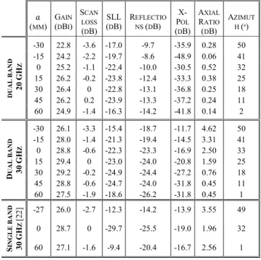
Table III – Dual-band transmit-array simulated performance at 20 GHz and 30 GHz, and comparison with the single-band lens developed in [22]
(MM) GAIN (DBI) SCAN LOSS (DB) SLL (DB) REFLECTIO NS (DB) X-POL (DB) AXIAL RATIO (DB) AZIMUT H (º) D U A L B A N D 20 G H Z -30 22.8 -3.6 -17.0 -9.7 -35.9 0.28 50 -15 24.2 -2.2 -19.7 -8.6 -48.9 0.06 41 0 25.2 -1.1 -22.4 -10.0 -30.5 0.52 32 15 26.2 -0.2 -23.8 -12.4 -33.3 0.38 25 30 26.4 0 -22.8 -13.1 -36.8 0.25 18 45 26.2 0.2 -23.9 -13.3 -37.2 0.24 11 60 24.9 -1.4 -16.3 -14.2 -41.8 0.14 2 D U A L B A N D 30 G H Z -30 26.1 -3.3 -15.4 -18.7 -11.7 4.62 50 -15 28.0 -1.4 -21.3 -19.4 -14.5 3.31 41 0 28.8 -0.6 -22.3 -23.3 -16.9 2.50 33 15 29.4 0 -23.0 -24.0 -20.8 1.59 25 30 29.2 -0.2 -24.9 -24.4 -27.2 0.76 18 45 28.8 -0.6 -24.7 -24.0 -31.8 0.45 11 60 27.5 -1.9 -18.6 -26.2 -31.8 0.45 1 S IN G L E B A N D 30 G H Z [2 2] -27 26.0 -2.7 -12.3 -14.2 -13.9 3.55 49 0 28.7 0 -29.7 -25.5 -19.0 1.96 32 60 27.1 -1.6 -9.4 -20.4 -16.7 2.56 1
IV. PROTOTYPE AND MEASUREMENTS
In order to experimentally validate the proposed dual-band transmit-array concept, a slightly trimmed square version of the previous transmit-array was considered with = = 119 mm as superimposed in Fig. 10. The same focal length
= 110 mm is used, so the phase correction is exactly the same, besides the truncation resulting from the smaller aperture considered. The corresponding CST model is shown in Fig. 12a. Two standard-gain horns (Flann Microwave Nº 20240-15 for 20 GHz and Flann Microwave Nº 22240-15 used for 30 GHz) are used as primary feeds for each band, producing, producing ‒10 dB field tapering at the transmit-array edge. The set-up ensures that the distance from the horns’ phase center to the lens is the same in both frequency bands. This requirement can be intrinsically satisfied in practical applications by using a single primary feed with appropriate dual-band operation [35]-[38].
It is noted that despite the fact that the fabricated transmit-array is smaller, it uses all the 30 developed unit-cells, while the phase correction function still involves two 360º phase jumps as can be seen in Fig. 12a. So the smaller prototype is good enough to demonstrate the physical viability of the proposed dual-band PD cells and validate its full-wave analysis in the context of a transmit-array operation compared to actual measurements. It is expected that the smaller size of the transmit-array will significantly affect the scan loss due to spill-over, but it is noted that the validation of the full size dual-band transmit-array performance in terms of gain, beam-pointing and scan-loss has already been demonstrated in the previous section.
The transmit-array fabrication procedure follows the same steps and procedures already detailed in [22], involving photolithographic patterning of each substrate layer compatible with 50 micron details, and substrate bonding using precise
layer alignment. The dielectric substrate extends 10 mm beyond the transmit-array cells edge to leave gripping area in the measurement set-up. The fabricated transmit-array plus the 3D printed supporting structure are shown in Fig. 13, mounted in the anechoic chamber positioner.
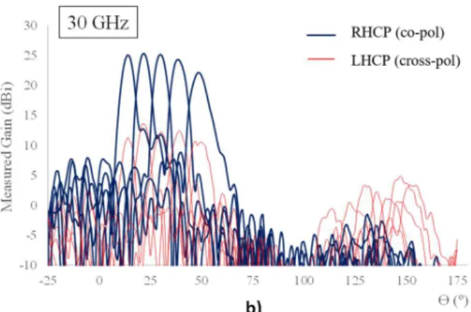
The measured and simulated normalized radiation patterns are shown for the feed central position ( = 0) in Fig. 14 and when the feed is translated between -30 mm and 30 mm with 15 mm step relative to the central position (Fig. 15). This excursion range is narrower than in the previous section (see
Table III) because the transmit-array is smaller. Consequently, a narrower scanning range will be shown. The magnitude normalization for the central positon in Fig. 14 is intended to show better the agreement between simulated and measured radiation patterns in terms of beam width and beam pointing direction in both bands. Graphical comparison for the other feed positions is omitted for conciseness, but the corresponding gain values are presented in Table IV. The degradation of the scanning performance of this transmit-array is in line with the explained spill-over effect. Overall, the results validate the numerical simulation model and its full-wave analysis, thus validating also the previous section. Moreover, they demonstrate that the proposed dual-band cell design strategy is viable and that its application for a complex dual-band transmit-array with wide-angle beam scanning is quite feasible at the Ka-band using common lab prototyping facilities.
Fig. 12 –a) Fabricated dual-band transmit-array.CST simulation model. b) Detail of the top layer metallization of the fabricated prototype. Each cell is
3.5×3.5 mm2.
Fig. 13 – Experimental setup: a) Schematics of the 3D-printed transmit-array support; b) prototyped antenna in the anechoic chamber.
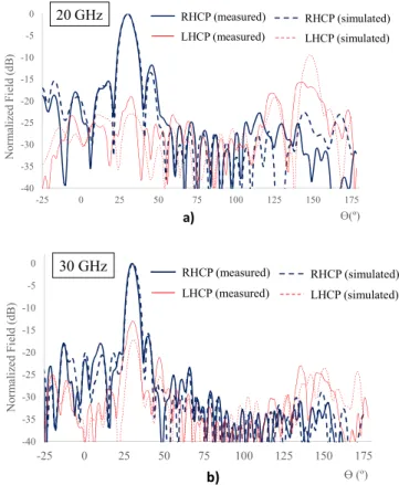
Fig. 14 – Normalized field patterns for circular polarization at: a) 20 GHz and;
b) 30 GHz.
Table IV – Measured and simulated gains obtained for the prototyped dual-band transmit-array. Gain (dBi) = −30 mm = −15 mm = 0 mm = 15 mm = 30 mm 20 G H z Simulated 21.0 22.9 24.1 25.4 25.1 Measured 20.3 22.3 24.0 24.7 24.6 30 G H z Simulated 24.1 26.2 27.4 27.5 27.9 Measured 23.5 25.8 26.8 26.9 27.2 -40 -35 -30 -25 -20 -15 -10 -5 0 -25 0 25 50 75 100 125 150 175 N or m al iz ed Fi el d (d B ) ϴ(º) a) RHCP (measured) LHCP (measured) RHCP (simulated) LHCP (simulated) 20 GHz -40 -35 -30 -25 -20 -15 -10 -5 0 -25 0 25 50 75 100 125 150 175 N or m al iz ed Fi el d (d B ) ϴ (º) RHCP (measured) LHCP (measured) RHCP (simulated) LHCP (simulated) 30 GHz b)
Fig. 15 ‒ Measured radiation patterns for circular polarization at: a) 20 GHz and; b) 30 GHz. The feed was shifted between -30 mm and 30 mm with 15
mm step relative to the central position.
V. CONCLUSIONS
The main contribution of this work is to present and demonstrate for the first time a general formulation to design arbitrarily large dual-band transmit-arrays. Unlike [22] and most of the established transmit-array designs in the literature, which refer to single-band solutions, the present paper advances the state of the art of transmit-arrays for high-gain, beam-steerable dual-band circular polarization solutions. Dual-band transmit-arrays are scarce in the literature and limited to low gain to avoid phase wrapping. The potential difficulty is related to the independent 360º phase wrapping needed at each band to compensate arbitrarily large equivalent length phase compensation. This points to an intractable number of phase combinations at each band, leading to a possibly very large number of different unit-cells. It is demonstrated in this paper that this phase compensation can be accomplished with a finite and limited number of appropriately selected dual-band unit-cells. For that purpose, a general procedure was developed, showing that the phase-pairs corresponding to the locus of the phase combinations of each unit-cell required for compensating arbitrarily large equivalent lengths fall on a set of parallel lines in a 360º-periodic plane (the RPP plane). Design rules based on this procedure were proposed. The method is valid both for phase-delay and phase rotation type of cells.
The concept was demonstrated for two off-set transmit-arrays with high gain and wide-angle beam scanning, one through full-wave simulation and the other through measurements of a fabricated prototype. The general configuration is based on a previous concept proposed by the authors, where the elevation steering is obtained by the feed in-plane translation under the transmit-array, while full azimuth coverage is obtained through rotation of the whole assembly. Dedicated dual-band cells were designed using the procedure developed in this paper.
The full-wave results of the full-size dual-band transmit-array are equivalent to those obtained for the single-band at 30 GHz that were demonstrated by measurements in a previous work from the authors [22]. The measured results from the fabricated dual-band transmit-array agree very well with full-wave simulations, thus validating it as well as the developed numerical model. A key point in both versions of the dual-band transmit-array is that while scanning, the beam pointing
direction is coincident over the two bands, an ultimate confirmation of the successful design.
To the best of the authors’ knowledge, there is no previous work in the literature reporting a dual-band transmit-array reaching 23-29 dBi gain, with a scanning interval as large as 0-50º, with scan loss better than 3.6 dB and F/D < 1. The proposed general approach to find a finite set of delay or phase-rotation cells for arbitrarily large dual-band transmit-arrays is also an original contribution of this work.
ACKNOWLEDGMENT
The authors acknowledge the discussions with Maarten van der Vorst and Stephane Prio. They are also indebted to Carlos Brito, Jorge Farinha and João Felício for prototype construction and António Almeida for prototype construction and measurements.
REFERENCES
[1] J. R. Costa, C. A. Fernandes, G. Godi, R. Sauleau, L. Le Coq, and H. Legay, “Compact Ka-Band Lens Antennas for LEO Satellites”, IEEE Trans. Antennas and Propag., vol. 56, pp. 1251 - 1258, May 2008. [2] Y. J. Cheng, P. Chen, W. Hong, T. Djerafi, and K. Wu,
“Substrate-Integrated-Waveguide Beamforming Networks and Multibeam Antenna Arrays for Low-Cost Satellite and Mobile Systems,” IEEE Antennas and Propag. Mag., vol. 53, No. 6, pp. 18 - 30, Dec. 2011.
[3] J. S. Silva, J. R. Costa, E. B. Lima, and C. A. Fernandes, “Ground Terminal Antenna for Ka-Band Satellite Communications,” Proc. 7th European Conf. Antennas and Propag., Gothenburg, Sweden, April 2013. [4] M. C. Viganó, D. L. del Río, F. Bongard, J. Padilla, and S. Vaccaro,
“One-bit Phased Array with Wide Scan and Linear Polarization Control for Mobile Satellite Applications,” Proc. 6th European Conf. Antennas and Propag. (EuCAP), pp. 1641 - 1644, Prague, Czech Republic, March 2012. [5] G. Bellaveglia, L. Marcellini, R. Lo Forti, A. Arcidiacono, and B. Ray, “Low Profile Ku-Band VSAT Antenna System for High-Speed Trains,” 29th ESA Antenna Workshop on Multiple Beams and Reconfigurable Antennas, ESA/ESTEC Noordwijk, Netherland, May 2007.
[6] N. Gagnon and A. Petosa, “Using Rotatable Planar Phase Shifting Surfaces to Steer a High-Gain Beam,” Antennas and Propagation, IEEE Transactions on, vol. 61, no. 6, pp. 3086-3092, June 2013.
[7] J.-M. Baracco, P. Ratajczak, P. Brachat, and G. Toso, “A dual frequency Ka-band printed fresnel reflector for ground terminal applications,” IEEE Trans. Antennas Propag., vol. 63, no. 10, pp. 4352-4366, Oct. 2015. [8] R. Deng, Y. Mao, S. Xu, and F. Yang, “A single-layer dual-band
circularly polarized reflectarray with high aperture efficiency,” IEEE Trans. Antennas Propag., vol. 63, no. 7, pp. 3317-3320, May 2015. [9] H. Bayer, A. Krauss, T. Zaiczek, R. Stephan, O. Enge-Rosenblatt, and M.
A. Hein, “Ka-Band user terminal antennas for satellite communications,” IEEE Antennas Propag. Mag., vol. 58, no. 1, pp. 76-88, Feb. 2016. [10] R. Lo Forti, G. Bellaveglia, A. Colasante, E. Shabirow, and M.
Greenspan, “Mobile Communications: High-Speed train Antennas from Ku to Ka,” Proc. 5th European Conf. Antennas and Propag. (EuCAP), pp. 2354 - 2357, Rome, Italy, April 2011.
[11] L. A. Greda and A. Dreher, “Tx-Terminal Phased Array for Satellite Communication at Ka-band,” Proc. 37th European Microwave Conf., pp. 266 - 269, Munich, Germany, Oct. 2007.
[12] M. Tripodi, F. DiMarca, T. Cadili, C. Mollura, F. DiMaggio, and M. Russo, “Ka Band Active Phased Array Antenna System for Satellite Communication on the Move Terminal,” Proc. 5th European Conf. Antennas and Propag. (EuCAP), pp. 2628 - 2630, Rome, Italy, April 2011.
[13] H. Bayer, A. Krauss, R. Stephan, and M. A. Hein, “A Dual-Band Multimode Monopulse Tracking Antenna for Land-Mobile Satellite Communications in Ka-Band,” Proc. 6th European Conf. Antennas and Propag. (EuCAP), pp. 2357 - 2361, Prague, Czech Republic, March 2012. [14] J. Thornton, A. White, and G. Long, “Multi-beam Scanning Lens Antenna
[15] T. Maruyama, K. Yamamori, and Y. Kuwahara, “Design of Multibeam Dielectric Lens Antennas by Multiobjective Optimization,” IEEE Trans. Antennas and Propag., vol. 57, pp. 57 - 63, Jan. 2009.
[16] J. R. Costa, E. B. Lima, and C. A. Fernandes, “Compact Beam-Steerable Lens Antennas for 60-GHz Wireless Communications,” IEEE Trans. Antennas and Propag., vol. 57, pp. 2926 - 2933, Oct. 2009.
[17] T. J. Cui, X. Zhou,, X. M.Yang, W. X. Jiang,Q. Cheng and H. F. Ma, “Several Types of Antennas Composed of Microwave Metamaterials,” IEICE Trans. Commun., vol E94–B, May 2011.
[18] J. S. Silva, J. R. Costa, E. B. Lima, and C. A. Fernandes, “Ground Terminal Antenna for Ka-Band Satellite Communications,” Proc. 7th European Conf. Antennas and Propag., Gothenburg, Sweden, April 2013. [19] M. Li, M. A. Al-Joumayly, and N. Behdad, “Broadband True-Time-Delay Microwave Lenses Based on Miniaturized Element Frequency Selective Surfaces,” IEEE Trans. Antennas and Propag., vol. 61, No. 3, pp. 1166 – 1179, Nov. 2012.
[20] M. Li and N. Behdad, “Wideband True-Time-Delay Microwave Lenses Based on Metallo-Dielectric and All-Dielectric Lowpass Frequency Selective Surface,” IEEE Trans. Antennas and Propag., vol. 61, No. 8, pp. 4109 – 4119, August 2013.
[21] N. Gagnon, A. Petosa, and D. A. McNamara, “Printed Hybrid Lens Antenna,” IEEE Trans. Antennas and Propag., vol. 60, No. 5, pp. 2514 – 2518, May 2012.
[22] E. B. Lima, S. A. Matos, J. R. Costa, C. A. Fernandes and N. Fonsenca, “Circular Polarization Wide-angle Beam Steering at Ka-band by In-plane Translation of a Plate Lens Antenna,” IEEE Trans. Antennas and Propag., vol. 63, No. 12, pp. 5443-5455, Dec. 2015.
[23] L. D. Palma, A. Clemente, L. Dussopt, R. Sauleau, P. Potier, and P. Pouligue, “Circularly Polarized Transmit-array With Sequential Rotation in Ka-Band,” IEEE Trans. Antennas and Propag., vol. 63, No. 11, pp. 5118-5124, Nov. 2015.
[24] N. Gagnon, A. Petosa, and D. A. McNamara, “Research and development on phase-shifting surfaces (PSSs),” IEEE Antennas and Propagation Magazine, vol. 55, No. 2, pp. 29-48, Apr. 2013.
[25] N. Gagnon, A. Petosa, and D. A. McNamara, “Printed hybrid lens antenna,” IEEE Trans. Antennas and Propag., vol. 60, No. 5, pp. 2514-2518, Mar. 2012.
[26] A. Ebrahimi, W. Withayachumnankul, S. Al-Sarawi and D. Abbott, “Design of Dual-band Frequency Selective Surface Dual band unit cells designs with Miniaturized Elements,” IEEE International Workshop on Antenna Technology (iWAT), pp. 206-209, 2014.
[27] L. Zheng, S. Qu, J. Zhang, J. Wang, H. Zhou, M. Yan, Z. Zhang, H. Yuan, Y. Li, and Y. Pang, “Investigating the Dual-passbands Frequency Selective Surface with Complementary Structure,” PIERS Proceedings, Guangzhou, China, August 25 28, 2014., pp 1494-1496.
[28] Parinaz Naseri, Rashid Mirzavand, and Pedram Mousavi, Dual-Band Circularly Polarized Transmit-Array Unit-Cell At X and K Bands, Proc. 10th European Conf. Antennas and Propag. (EuCAP), Davos, Switzerland, April 2016.
[29] H. Hasani, J. S. Silva, J. R. Mosig, M. Garcia-Vigueras, “ Dual-Band 20/30 GHz Circularly Polarized Transmit-array for SOTM Applications,” Proc. 10th European Conf. Antennas and Propag. (EuCAP), Davos, Switzerland, April 2016.
[30] S. A. Matos, E. B. Lima, J. R. Costa, C. A. Fernandes, N. Fonseca, “Prototype of a compact mechanically steered Ka-band antenna for satellite on-the-move,” IEEE AP-S/URSI International Symp., Fajardo, Puerto Rico, June 2016.
[31] D. M. Pozar, S. D. Targonski, and H. D. Syrigos, “Design of millimeter wave microstrip reflectarrays,” IEEE Trans. Antenna Propag., vol. 45, No. 2, pp. 287–296, Feb. 1997.
[32] CST Microwave Studio – Computer Simulation Technology: http://www.cst.com/ [Jun. 2016].
[33] P. F. Goldsmith, "Zone plate lens antennas for millimeter and submillimeter wavelengths," The Third International symposium on Space Terahertz Technology, pp. 345 - 361, 1992
[34] B. Y. Toh, R. Cahill, and V. F. Fusco, “Understanding and measuring circular polarization,” IEEE-Trans. on Education, vol. 46, No. 3, Aug. 2003.
[35] J. E. Lee, “The Development, Variations, and Applications of an EHF Dual-Band Feed,” The Lincoln Laboratory Journal, vol. 4, No. 1, 1991. [36] L. Lucci, R. Nesti, G. Pelosi, and S. Selleri, “Phase center optimization in
profiled corrugated circular horns with parallel genetic algorithms,” Progress In Electromagnetics Research, vol. 46, pp. 127–142, 2004.
[37] J. S. Silva, E. B. Lima, J. R. Costa, C. A. Fernandes, and J. R. Mosig, “Tx-Rx Lens-Based Satellite-on-the-Move Ka-Band Antenna,” IEEE Antennas and Wireless Propagation Letters, vol. 14, pp. 1408-1411, 2015. [38] J. S. Silva, M. García-Vigueras, M. Esquius-Morote, J. R. Costa, C. A. Fernandes, J. R. Mosig, “A Planar Feed for SOTM Ka-band Lens Antennas” IEEE AP-S/URSI International Symp., Vancouver, Canada, July 2015.
Sérgio A. Matos (S’05–M’16) received the Licenciado, M.Sc., and Ph.D. degrees in electrical and computer engineering from Instituto Superior Técnico (IST), University of Lisbon, Lisbon, Portugal, in 2004, 2005, and 2010, respectively.
He is currently a Researcher with the Instituto de Telecomunicações (IT), Lisbon, Portugal. He is also an Assistant Professor at the Departamento de Ciências e Tecnologias da Informação, Instituto Universitário de Lisboa (ISCTE-IUL). He is the co-author of 60 technical papers in international journals and conference proceedings. His present research interests include electromagnetic wave propagation in metamaterials, flat-lens design and transmit arrays.
Eduardo B. Lima (S’14) received the Licenciado and M.Sc. degrees in electrical and computer engineering from the Instituto Superior Técnico (IST), Technical University of Lisbon, Portugal in 2003 and 2008, respectively. He is currently a PhD student at IST and a Researcher at Instituto de Telecomunicações (IT), Lisbon, Portugal. Since 2004 he is also responsible for development and maintenance of all measurement control systems at the RF laboratories. He is the co-author of one patent application and 32 technical papers in international journals and conference proceedings in the area of antennas. One of which was awarded the CST University Publication Award 2010. His present research interests include dielectric lens antennas, Fabry-Pérot cavity antennas and transmit arrays. He is currently serving as a Technical Reviewer for IEEE Transactions on Antennas and Propagation (TAP). He is serving as a TPC member in the upcoming EuCAP2015 conference.
Joana S. Silva was born in Lisbon, Portugal, in 1988. She received the B.Sc. and M.Sc. degrees in Telecommunications and Computer Science Engineering from ISCTE – Instituto Universitário de Lisboa, Lisbon, Portugal, in 2010 and 2012, respectively. Since 2012 she is working towards the Ph.D. degree in Electrical Engineering jointly at École Polytechnique Fédérale de Lausanne, Lausanne, Switzerland, and the Instituto Superior Técnico – Universidade de Lisboa, Lisboa, Portugal. Her current research interest is the design and analysis of Ka-band antennas.
Jorge R. Costa (S’97–M’03–SM’09) was born in Lisbon, Portugal, in 1974. He received the Licenciado and Ph.D. degrees in electrical and computer engineering from the Instituto Superior Técnico (IST), Technical University of Lisbon, Lisbon, Portugal, in 1997 and 2002, respectively. He is currently a Researcher at the Instituto de Telecomunicações, Lisbon, Portugal. He is also an Associate Professor at the Departamento de Ciências e Tecnologias da Informação, Instituto Universitário de Lisboa (ISCTE-IUL). His present research interests include lenses, reconfigurable antennas, MEMS switches, UWB, MIMO and RFID antennas. He is the coauthor of four patent applications and more than 150 contributions to peer reviewed journals and international conference proceedings. More than thirty of these papers have appeared in IEEE Journals. Prof. Costa served as an Associate Editor for the IEEE Transactions on Antennas and Propagation from 2010 to 2016 and he was a Guest Editor of the Special Issue on “Antennas and Propagation at mm- and Sub mm-Waves”, from the IEEE Transactions on Antennas and Propagation, April 2013. He was the Co-Chair of the Technical Program Committee of the European Conference on Antennas and Propagation (EuCAP 2015) in Lisbon and General Vice-Chair of EuCAP 2017 in Paris.
Carlos A. Fernandes (S’86–M’89–SM’08) received the Licenciado, MSc, and PhD degrees in Electrical and Computer Engineering from Instituto Superior Técnico (IST), Technical University of Lisbon, Lisbon, Portugal, in 1980, 1985, and 1990, respectively. He joined IST in 1980, where he is presently Full Professor at the Department of Electrical and Computer Engineering in the areas of microwaves, radio wave propagation and antennas. He is a senior researcher at the Instituto de Telecomunicações and member of the Board of Directors. He has co-authored a book, 2 book chapter, more than 180 technical papers in peer reviewed international journals and conference proceedings and 7 patents in the areas of antennas and radiowave propagation modeling. His current research interests include dielectric antennas for millimeter wave applications, antennas and propagation modeling for personal communication systems, RFID and UWB antennas, artificial dielectrics and metamaterials. He was a Guest Editor of the Special Issue on “Antennas and Propagation at and Sub mm-Waves”, from the IEEE Transactions on Antennas and Propagation, April 2013.
Nelson J. G. Fonseca (M’06–SM’09) was was born in Ovar, Portugal, in 1979. He received the M.Eng. degree from Ecole Nationale Supérieure d’Electrotechnique, Electronique, Informatique, Hydraulique et Telecommunications (ENSEEIHT), Toulouse, France, in 2003, the M.Sc. degree from the Ecole Polytechnique de Montreal, Montreal, QC, Canada, also in 2003, and the Ph.D. degree from the Institut National Polytechnique de Toulouse – Université de Toulouse, Toulouse, France, in 2010, all in electrical engineering.
He worked as an antenna engineer successively with the Department of Antenna Studies, Alcatel Alénia Space, Toulouse, France (now Thalès Alénia Space), and with the Antennas Section, French Space Agency (CNES), Toulouse, France, where he completed his Ph.D. degree in parallel of his professional activities. In 2009, he joined the Antenna and Sub-Millimetre Wave Section, European Space Agency (ESA), Noordwijk, The Netherlands, as an employee of Moltek Consultants Ltd, Kent, U.K. His research interests include the telecommunication antennas, beam formers theory and design, andnew enabling technologies such as fractals and metamaterials applied to antenna design. He has authored or co-authored more than 130 papers in journals, conferences and specialized workshops. He contributed to 17 technical innovations, protected by over 30 patents issued or pending . Dr. Fonseca received several prizes, including the best young engineer paper award at the 29th ESA Workshop on Antennas in 2007. He served or is currently serving as a technical reviewer for several journals, including the IEEE Transactions on Antennas and Propagation (TAP) and the IEEE Transactions on Microwave Theory and Techniques (TMTT).
Juan R. Mosig (S’76–M’87–SM’94–F’99) was born in Cádiz, Spain. He received the Electrical Engineer degree from the Universidad Politécnica de Madrid, Madrid, Spain, in 1973, and the Ph.D. degree in electrical engineering from the École Polytechnique Fédérale de Lausanne (EPFL), Lausanne, Switzerland, in 1983. Since 1991, he has been a Professor with the Laboratory of Electromagnetics and Acoustics (LEMA) at EPFL and its Director since 2000. He has held scientific appointments with the Rochester Institute of Technology, Rochester, NY, USA; the Syracuse University, Syracuse, NY, USA; the University of Colorado at Boulder, Boulder, CO, USA; University of Rennes, Rennes, France; University of Nice, Nice, France, the Technical University of Denmark, Lyngby, Denmark. He has authored four chapters in books on microstrip antennas and circuits and over 150 reviewed papers. He has also directly supervised more than 30 Ph.D. theses. His research interests include electromagnetic theory, numerical methods, and planar antennas.
Dr. Mosig has been the Swiss Delegate for European COST Antenna Actions since 1985 and the Chair for the two last Actions 284 and IC0603 ASSIST (2003–2011). From 2004–2007, he was Vice-Coordinator of the FP6 Network of Excellence ACE, that enabled the EuCAP Conference series. He also has served as a Member of the Board in the Coordination Actions ARTIC (FP6) and CARE (FP7) and Transnational Delegate in the IEEE APS AdCom. He is a founding member and Chair of the European Association on Antennas and Propagation (EurAAP) and he also chairs the EuCAP Conferences series and its Steering Committee. He also founded (2006) and conducts the series of INTELECT International Workshops on Computational Electromagnetics.
![Fig. 1 – Antenna geometry, same as in [30]](https://thumb-eu.123doks.com/thumbv2/123dok_br/18684614.914733/3.892.460.825.699.874/fig-antenna-geometry-same-as-in.webp)