Department of Information Science and Technology
Model-Driven Generative Programming
for BIS Mobile Applications
Luís Miguel Pires Teixeira da Silva
A dissertation in partial fulfillment of the requirements for the degree of
Master in Computer Science and Business Management
Supervisor:
Fernando Brito e Abreu, PhD, Associate Professor DCTI, ISTA
Acknowledgments
I would like to thank:
– to my family, for all the given support and for the patience shown during the realization of this master thesis;
– to all my friends, for the encouragement and positive criticism which helped me guide and improve this thesis;
– to all the participants that were part of the experiments performed in this master thesis, for their commitment and dedication;
– to Prof. Fernando Brito e Abreu, which supervised this master thesis, for all the time and dedication, not only to this thesis but also to me, in both good and bad times.
Abstract
The burst on the availability of smart phones based on the Android platform calls for cost-effective techniques to generate mobile apps for general purpose, distributed business information systems (BIS). To mitigate this problem our research aims at applying model-driven techniques to automatically generate usable prototypes with a sound, maintainable, architecture. Following three base principles: model-based generation, separation of concerns, paradigm seamlessness, we try to answer the main guiding question – how to reduce development time and cost by transforming a given domain model into an Android application?
To answer this question we propose to develop an application that follows a generative approach for mobile BIS apps that will mitigate the identified problems. Its input is a platform independent model (PIM), with business rules specified in OCL (Object Constraint Language). We adopted the Design Science Research methodology, that helps gaining problem understanding, identifying systemically appropriate solutions, and in effectively evaluating new and innovative solutions. To better evaluate our solution, besides resorting to third party tools to test specific components integration, we demonstrated its usage and evaluated how well it mitigates a subset of the identified problems in an observational study (we presented our generated apps to an outside audience in a controlled environment to study our model-based centered and, general apps understandability) and communicated its effectiveness to researchers and practitioners.
Keywords: Model-driven development, source code generation, Unified Modeling Language (UML),
Resumo
O grande surto de disponibilidade de dispositivos móveis para a plataforma Android requer, técnicas generativas de desenvolvimento de aplicações para sistemas comuns e/ou distribuídos de informação empresariais/negócio, que otimizem a relação custo-benefício. Para mitigar este problema, esta investigação visa aplicar técnicas orientadas a modelos para, automaticamente, gerar protótipos funcionais de aplicações com uma arquitetura robusta e fácil de manter. Seguindo para tal três princípios base: geração baseada no modelo, separação de aspetos, desenvolvimento sem soturas (sem mudança de paradigma), tentamos dar resposta à pergunta orientadora – como reduzir o tempo e custo de desenvolvimento de uma aplicação Android por transformação de um dado modelo de domínio?
De modo a responder a esta questão nós propomos desenvolver uma aplicação que segue uma abordagem generativa para aplicações de informação empresariais/negócio móveis de modo a mitigar os problemas identificados. Esta recebe modelos independentes de plataforma (PIM), com regras de negócio especificadas em OCL (Object Constraint Language). Seguimos a metodologia Design Science Research que ajuda a identificar e perceber o problema, a identificar sistematicamente soluções apropriadas aos problemas e a avaliar mais eficientemente soluções novas e inovadoras. Para melhor avaliar a nossa solução, apesar de recorrermos a ferramentas de terceiros para testar a integração de componentes específicos, também demonstramos a sua utilização, através de estudos experimentais (em um ambiente controlado, apresentamos as nossas aplicações geradas a uma audiência externa que nos permitiu estudar a compreensibilidade baseada e centrada em modelos e, de um modo geral, das aplicações) avaliamos o quanto esta mitiga um subconjunto de problemas identificados e comunicamos a sua eficácia para investigadores e profissionais.
Palavras-chave: Desenvolvimento orientado por modelos, geração de código fonte, Linguagem de Modelação Unificada (UML), padrões de desenho, prototipagem de software, desenvolvimento de software orientado a objetos.
Index
ACKNOWLEDGMENTS ... I ABSTRACT ... III RESUMO... V INDEX ... VII LIST OF FIGURES ... XI LIST OF TABLES ... XIII GLOSSARY ... XV 1 – INTRODUCTION ... 1 1.1–GENERAL INTRODUCTION ... 1 1.2–MOTIVATION ... 1 1.3–GOALS ... 4 1.4–CONTRIBUTIONS ... 5 1.5–DISSERTATION GUIDELINES ... 5 1.6–DISSERTATION STRUCTURE ... 6 2 – RELATED WORK ... 7 2.1–INTRODUCTION ... 72.2–ANDROID SPECIFIC RELATED WORK ... 7
2.3–OTHER RELATED APPROACHES... 8
2.3.1 – Dresden OCL ... 8
2.3.2 – OCLE (OCL Environment) ... 8
2.3.3 – The Naked Objects approach ... 9
2.4–CONCLUSIONS ... 9
3 – METHODOLOGY ... 13
3.1–EXPLORATORY PHASE ... 14
3.2–DEVELOPMENT PHASE ... 14
3.2.1 – Development of a prototypical Android BIS application ... 14
3.2.2 – Development of the proposed artefact... 14
3.2.3 – Generator Validation ... 15
3.3–RESULTS EVALUATION ... 15
4 – DOMAIN AND GUI SPECIFICATION ... 17
4.1–INTRODUCTION ... 17
4.2–DOMAIN SPECIFICATION (PIM) ... 17
4.3.1 – Model-driven navigation metaphor ... 20
4.3.2 – GUI views and widgets ... 21
4.3.3 – Objects and links creation ... 23
4.3.4 – Server synchronization support ... 24
5 – ANDROID APPS TECHNOLOGICAL REQUIREMENTS ... 25
5.1–ANDROID ... 25
5.2–ANDROID APPLICATIONS STRUCTURE ... 25
5.2.1 – Architecture ... 25
5.2.2 – General structure and functionality ... 26
5.3–ANDROID PERSISTENCY ... 34
5.3.1 – Persistency ... 34
5.3.2 – ORM libraries for Android ... 38
5.3.3 – The DB4O OODBMS ... 38
5.4–ANDROID PATTERNS... 41
5.5–ANDROID FRAGMENTS ... 41
5.5.1 – Static versus dynamic approach ... 42
5.6–ANDROID LIFECYCLES ... 42
6 – GENERATED APPS STRUCTURE ... 49
6.1–GENERIC ARCHITECTURE ... 49
6.2–VIEW LAYER ... 52
6.2.1 – Concerns ... 52
6.2.2 – View Layer structure ... 53
6.2.3 – Reaching several screens sizes and densities ... 54
6.3–VIEW-MODEL ... 55 6.3.1 – Concerns ... 55 6.3.2 – Binding Layer ... 55 6.4–MODEL LAYER ... 59 6.4.1 – Concerns ... 59 6.4.2 – POJO classes ... 59 6.4.3 – Access class ... 59 6.5–PERSISTENCY LAYER ... 60 6.5.1 – Concerns ... 60 6.5.2 – Database ... 60
6.6–UTILS –SUPPORT LAYER/PACKAGE ... 61
6.6.1 – Concerns ... 61
6.6.2 – Generated support classes ... 61
6.7–SYNCHRONIZATION ... 63
6.8–IMPLEMENTED PATTERNS ... 64
6.8.1 – List view holder ... 64
6.8.2 – Observer pattern ... 65
6.8.3 – Command pattern ... 66
7 – JUSE4ANDROID ... 67
7.1–JUSE4ANDROID –GUI AND REQUIREMENTS ... 67
7.2–JUSE4ANDROID –STRUCTURE AND GENERATION PROCESS ... 68
7.2.1 – Open-source tool integration ... 68
7.2.2 – GUI and generator – project and standalone ... 69
7.2.3 – Internal generator structure ... 70
7.2.4 – Static generation process ... 73
7.3–MODEL TRANSFORMATION ... 73 7.3.1 – View Layer ... 73 7.3.2 – Type mapping ... 80 7.3.3 – View-Model layer ... 81 7.3.4 – Model layer ... 83 7.3.5 – Persistency layer ... 86 7.3.6 – Static implementations ... 87 8 – VALIDATION ... 89 8.1–GENERATED IMPLEMENTATION ... 89
8.1.1 – Seamlessness validation – Persistency and Model layers ... 89
8.1.2 – Validating – View-Model and View layers ... 92
8.1.3 – Validating – Understandability – UI layer and flow control ... 92
8.2–JUSE4ANDROID ... 98
8.2.1 – Generator tool based on a PIM ... 98
8.2.2 – Code production – Time to market ... 98
8.2.3 – Scalability ... 99
9 – CONCLUSIONS AND FUTURE WORK ... 101
9.1–CONCLUSIONS ... 101
9.2–FUTURE WORK ... 102
9.2.1 – Systematic comparison/Software evolution ... 102
9.2.2 – Business rules enforcement ... 103
9.2.3 – Scalability ... 103 9.2.4 – Internationalization ... 104 9.2.5 – Portability ... 104 9.2.6 – Reliability ... 104 BIBLIOGRAPHY ... 105 APPENDIX ... 109
A.PROJECTS WORLD –USE SPECIFICATION ... 110
B.PERSISTENCY –DB4O ... 113
1. Usage ... 113
2. DB4O vs SQLite – seamlessness ... 114
C.STATIC GENERATION PROCESS – IDENTIFIERS ... 116
1. Utils layer ... 116
2. View layer ... 118
D.POJO–RELATIONAL GETTERS AND SETTERS EXAMPLE ... 119
E.MODELS ... 121
List of Figures
Figure 1 – Software market in EU27 in M€ (adapted from (Aumasson et al. 2010)) ... 2
Figure 2 – Gartner’s magic quadrant – Mobile Application Development Platform vendors ... 4
Figure 3 – Followed methodology lifecycle ... 14
Figure 4 – Projects World UML class diagram ... 18
Figure 5 – Projects World launcher screen... 21
Figure 6 – Screen Division – Worker Class Example ... 22
Figure 7 – Alert icon ... 22
Figure 8 – Dialog when navigate in WRITE mode to Project ... 23
Figure 9 – Available options in WRITE mode ... 23
Figure 10 – Synchronization button ... 24
Figure 11 – Model View Controller pattern ... 26
Figure 12 – Layout building blocks ... 30
Figure 13 – Illustration of a view hierarchy, which defines a UI layout ... 31
Figure 14 – User Interface Tree – Illustrating example ... 32
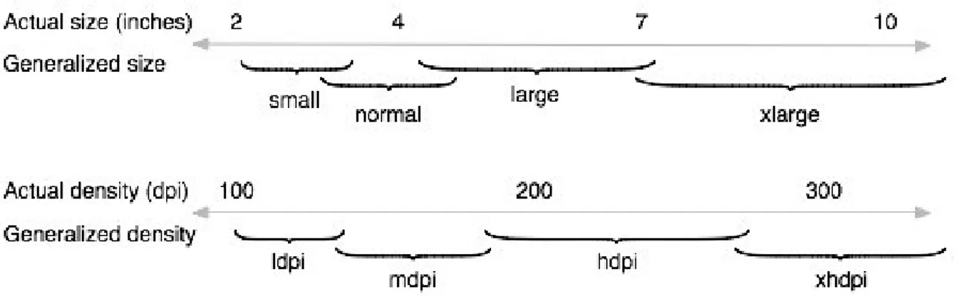
Figure 15 – Approximate map of Android devices sizes and densities to generalized sizes and densities ... 33
Figure 16 – Object-Oriented Model many-to-many relationship with UML example ... 37
Figure 17 – Relational model many-to-many relationship with SQL example... 37
Figure 18 – Database engines – market share ... 39
Figure 19 – MySQL, NoSQL and NewSQL compound annual growth rate ... 39
Figure 20 – Activities lifecycle. ... 44
Figure 21 – Fragments lifecycle. ... 45
Figure 22 – Fragment lifecycle intersection with activity state. ... 46
Figure 23 –Activity recreation lifecycle. ... 47
Figure 24 – Model View View-Model ... 50
Figure 25 – Generated applications architecture (UML component diagram) ... 51
Figure 26 – Generated client-side apps main architecture ... 52
Figure 27 – Proposed Android View Layer Structure ... 53
Figure 28 – UI components styles reference structure ... 54
Figure 29 – Google Master Detail Flow design recommendation ... 58
Figure 30 – List view holder pattern ... 65
Figure 31 – Observer pattern ... 65
Figure 32 – Command pattern ... 66
Figure 33 – JUSE4Android GUI screen ... 67
Figure 34 – JUSE4Android Standalone mains structure ... 70
Figure 35 – JUSE4Android package diagram ... 71
Figure 36 – JUSE4Android relation to J-USE and Visit pattern class diagram ... 72
Figure 38– Form XML template and worker detail form example ... 75
Figure 39 – Association Creation to Inheritance Tree example (worker class screen) ... 80
Figure 40 – Aggregated associative classes’ example ... 82
Figure 41 – ProjectWorlds analysis decisions – example. ... 83
Figure 42 – Insert method – Worker class example ... 85
Figure 43 – ProjectWorld Worker class – OME and generated Android Application validation example – Application view ... 90
Figure 44 – ProjectsWorld Worker class – OME and generated Android Application validation example ... 91
Figure 45 – AirNova UML class diagram ... 121
Figure 46 – Royal & Loyal UML class diagram ... 122
Figure 47 – Football Leagues UML class diagram ... 123
List of Tables
Table 1 – Android version evolution and actual (2/10/2013) app versioning distribution ... 3
Table 2 – Strengths and weaknesses of generative tools and/or approaches ... 10
Table 3 – MADP taxonomy categories ... 11
Table 4 – Design research criteria. Source: (Hevner and Chatterjee 2010) ... 13
Table 5 – Available annotation types ... 19
Table 6 – Navigation Icons ... 20
Table 7 – Available ORMs solutions for Android ... 38
Table 8 – Db4o versus SQLite – main feature comparison ... 40
Table 9 – DB4O different querying capabilities example ... 41
Table 10 – Support classes ... 62
Table 11 – Command class attributes ... 64
Table 12 – OCL tools differences ... 69
Table 13 – Naming convention qualifiers ... 74
Table 14 – OCL type to UI components (widget) transformation – detail XML ... 76
Table 15 – OCL type to UI components (widget) transformation – InsertUpdate XML ... 77
Table 16 – Navigation Bar association view group settings ... 77
Table 17 – Detail and InsertUpdate Views XML templates ... 78
Table 18 – OCL to Java types mapping ... 80
Table 19 – Collection OCL to Java type mapping ... 81
Table 20 – Deletion notification – Mapping solutions ... 86
Table 21 – Subject knowledge categories ... 93
Table 22 – Participants universe and sample description ... 94
Table 23 – Experiment two results ... 97
Table 24 – Test two final results ... 98
Table 25 – Code generated – ProjectsWorld example ... 99
Table 26 – Code generated – Royal & Loyal ... 99
Glossary
TERM DEFINITION
ACID Atomicity, Consistency, Isolation and Durability
ADT Android Development Tools
API Application Programming Interface
BIS Business Information System
CASE Computer- Aided Software Engineering CRUD Create, Read, Update and Delete
DAO Data Access Object
DB4O Database for Objects
DBMS Database Management System
EMF Eclipse Modeling Framework
GUI Graphical User Interface
JPA Java Persistency API
LOC Lines of Code
MADP Mobile Application Development Platform
MDA Model-Driven Architecture
MDD Model-Driven Development
MDT Model Development Tools
MVC Model View Controller
MVVM Model View View-Model
OCL Object Constraint Language
OODBMS Object-Oriented Database Management System ORDBMS Object Relational Database Management System
ORM Object Relational Mapping
PIM Platform-Independent Model
POJO Plain Old Java Object
PSM Platform-Specific Model
SODA Simple Object Database Access
SQL Structured Query Language
RDBMS Relational Database Management System
UI User Interface
WPF Windows Presentation Foundation
XMI XML Metadata Interchange
1 – Introduction
1.1–GENERAL INTRODUCTION ... 1 1.2–MOTIVATION ... 1 1.3–GOALS ... 4 1.4–CONTRIBUTIONS ... 5 1.5–DISSERTATION GUIDELINES ... 5 1.6–DISSERTATION STRUCTURE ... 61.1 – General introduction
The burst on the availability of smart phones and tablets based on the Android platform calls for cost-effective techniques to generate mobile apps for general purpose, distributed business information systems (BIS). What drove us in doing this research was the need to find a better solution for the time consuming app creation problem, as recognized in (Parada and Brisolara 2012): “Developing applications for mobile platforms demands additional worries such as code efficiency, interaction with device resources, as well as short time-to-market”.
1.2 – Motivation
The aforementioned burst characterizes the growing mobile business ecosystem (Basole and Karla 2011). This concept is based on the ecological metaphor that firms are part of a larger ecosystem, each occupying a contributing role and forming symbiotic relationships with customers, suppliers, and competitors. This ecosystem is fuelled by the emergence of an “App Economy”, enabling new products and services, but also influencing strategies and shaping business models (Page et al. 2013). For instance, according to the forecasts for the software market in the EU27 region, the apps share is the fastest growing one and will account for roughly half of that market by 2020 (see Figure 1).
Figure 1 – Software market in EU27 in M€ (adapted from (Aumasson et al. 2010))
The expanding mobile ecosystem will put an increasing pressure in the demand for mobile business information systems (BIS) apps, therefore enforcing the aforementioned short time-to-market requirements (Parada and Brisolara 2012).
BIS apps target specific business-to-business or business-to-consumer problems and therefore they must be built “from scratch” to answer each business requirement. Furthermore, as aforementioned, developing such applications is a challenging task, due to several technical hindrances. Some are generic, such as the need to support localization features, and others are specific to mobile devices, such as the ability to support the diversity of available deployment platforms (e.g. diverse screen sizes, resolutions and orientation). The combination of these factors greatly increases both development time and cost.
The fast release pace of new Android versions also stands as a maintainability concern. As we can see in Table 1 (Wikipedia 2013a), the average period between each “major” release is around one year. Furthermore, notice that even the market is not able to follow the releases, showing still a large 28.5% usage of the 2.3 – 2.3.2 version. The API (Application Provided Interface – Interfaces that ease the implementation and/or provide functions to control specific system behaviors) level is also different for each released version. The greater it is, the more functionalities and easier interfaces are available for developers. Moreover, if we target the latest releases, a big portion of the market will not be able to use our application. The latter is an important fact since, even the application base structure might change depending on the level of the targeted API. For instance, the Honeycomb (API level 12) introduced the concept of fragments which drastically changed how applications can be structured.
ecosystem, providing a generative approach will facilitate maintainability and therefore will mitigate the problem of BIS apps migration due to platform evolution.
Table 1 – Android version evolution and actual (2/10/2013) app versioning distribution
Version Code name Release date API level Distribution
1.5 Cupcake April 30, 2009 3 0% 1.6 Donut September 15, 2009 4 0% 2.0–2.1 Eclair October 26, 2009 7 0% 2.2 Froyo May 20, 2010 8 2.2% 2.3–2.3.2 Gingerbread December 6, 2010 9 0% 2.3.3–2.3.7 Gingerbread February 9, 2011 10 28.5% 3.1 Honeycomb May 10, 2011 12 0% 3.2 Honeycomb July 15, 2011 13 0.1%
4.0.3–4.0.4 Ice Cream Sandwich December 16, 2011 15 20.6%
4.1.x Jelly Bean July 9, 2012 16 36.5%
4.2.x Jelly Bean November 13, 2012 17 10.6%
4.3.x Jelly Bean July 24, 2013 18 1.5%
4.4 KitKat October 31, 2013 19 0%
Due to these facts, we believe that model-driven generative approaches will in time become mainstream in BIS application development.
According to Gartner’s viewpoint (Riza Babaoğlan 2013) mobile application development platforms (MADP) are generally based on one of three technologies. Each technology requires different investments and skills: native toolkits (e.g. Apple’s iOS development toolkit), web toolkits (e.g. jQuery Mobile) and specialized platforms. Our approach fits in this last category. As claimed in (Riza Babaoğlan 2013), “Specialized platforms take a more proprietary route, but generally provide more out-of-the-box enterprise capability than Web and native toolkits. They also often address more of the full software development life cycle — from application design, development and integration to testing, deployment and management. Some specialized platforms are optimized for high developer productivity, and others are optimized for high application performance and developer control”. Also, as shown in the latter, our approach falls, regarding the MADP market vendors, in the category of application generators, the same as Kony, that, as it can be seen in Figure 2, is considered one of the leaders.
Figure 2 – Gartner’s magic quadrant – Mobile Application Development Platform vendors1
1.3 – Goals
Our main goal is to understand how to reduce development time and cost by transforming a
given domain model into an Android application.
In order to fulfil the previous goal we must answer a more technical set of goals, namely the identification of adequate solutions to:
Integrate different technologies;
Generate an extendible and maintainable software architecture;
Persist app data locally (required for offline usage), while being able to synchronize it with other users using the same app.
Our research aims at applying model-driven techniques to automatically generate usable prototypes with a sound, maintainable, architecture. Our generative approach is targeted to Android devices and we have adopted three principles to facilitate understandability and extensibility:
Model centered generation – everything follows the model, from GUI to persistence;
http://www.alibabaoglan.com/blog/gartner-2013-magic-quadrant-mobile-application- Separation of concerns – there is a clear separation in layers or components, each encapsulating a concern of its own;
Paradigm seamlessness – the object paradigm is used throughout, since both the host language and data storage share the same type system, thus avoiding type conversions (e.g. from object to relational and vice-versa).
To reify the aforementioned principles we propose to: (i) generate GUIs that allow a conceptual navigation based on the type of relationships among domain entities (as described in a UML class diagram); use a GUI architecture that avoids code repetition and supports several screen sizes, resolutions and orientations; (ii) apply an architecture that separates different concerns in layers and apply already proven design patterns; (iii) allow seamless data persistence by using an object-oriented database; and finally (iv) grant distributed access by generating a simple Java server-side application, which allows data synchronization among mobile devices.
By providing a tool capable of generating robust and usable prototypes, we will free developers from repetitive tasks and by applying proven architectures and patterns developers will be able to extend or adapt the generated implementation – in case it does not fulfil the defined requirements or the domain model does not provide the means to represent them.
1.4 – Contributions
The main contribution of this dissertation is the proposal of a model-driven approach for automatic generation of Business Information Systems applications, to run in the Android platform. We also propose a model-based representation and navigation scheme for our BIS apps. Given that the generation targets a mobile platform, performance, screen size and resolution are main concerns which make development harder. We will introduce our approach to reach different screen sizes and resolutions with “minimal” effort, and to control screen orientation change in Android. We will also describe how we applied good development practices to an Android application, and how we implemented the already existing Android design patterns.
1.5 – Dissertation Guidelines
Given the fact that we are proposing a generative approach that focus in different areas, as consequence there are terms which affect different actors depending on the targeted area. Therefore during this dissertation the following concepts are going to be applied to better differentiate the influenced actors.
The actors are:
Tool engineer – – mainly composed by technology/programming experts actors responsible for the generative approach.
Domain expert – – mainly composed by business dedicated actors, responsible for the domain model specification and/or final app creation.
Final user – – composed by every actor that may use the outcome final applications. Along this dissertation, the given symbols will be placed next to a given requirement, in order to indicate the actors that will be affected by it.
1.6 – Dissertation structure
This dissertation is structured as follows: chapter two, the state of art, describes the current situation regarding the model-driven generative programming for the Android platform and also a brief exploration over generative approaches and tools for other platforms, but that are closer to our own approach. In chapter three we present our methodology. In chapter four, we present our solution. Chapter five presents a general review of all technologies used to support our generative approach, and a general explanation of the Android platform. In chapter six we describe the implementation of the chosen technologies, we explain the decisions, present and explain our approach regarding the generated applications. Chapter seven presents the research outcome, the JUSE4Android tool. Here it is explained the generator implementation, we explain the decisions and, present and explain our approach regarding our generative approach. Chapter eight, validates the decisions and approaches. Finally, in chapter nine, we draw our conclusions, review our contributions and forecast the future work.
2 – Related work
2.1–INTRODUCTION ... 7 2.2–ANDROID SPECIFIC RELATED WORK ... 7
2.3–OTHER RELATED APPROACHES... 8 2.4–CONCLUSIONS ... 9 3.1–EXPLORATORY PHASE ... 14 3.2–DEVELOPMENT PHASE ... 14 3.3–RESULTS EVALUATION ... 15
2.1 – Introduction
Model-driven generative approaches and tool development has been the subject of research since the eighties, by then under the CASE (Computer-Aided Software Engineering) acronym (Wikipedia 2013c). In this chapter we will survey and comment related generative approaches. Ideally they would be targeted for Android apps, use UML for model specification and Java/XML for implementation. In some cases, that related work only covers some of these requirements.
2.2 – Android specific related work
There are already some available software tools that generate code for Android apps, namely: Basic4Android (Uziel 2013) and App Inventor (MIT 2013). Despite the usefulness of these tools, our goals are different. Basic4Android is a commercial tool to speed up development by providing an IDE that allows a simple visual programming development style, allowing detailed customizations. App Inventor is based on MIT's Open Blocks (Roque 2007), a graphical programming system especially suited for novice programmers. Although providing a more user friendly development environment, using these tools for developing BIS apps would require a lot of development effort, namely because it does not provide an adequate level of abstraction. For instance, regarding persistency actions, two different entities may behave the same way, In such approaches we must describe every aspect of such actions, for each entity, independently of being the exact same action or not.
In (Parada and Brisolara 2012) the authors also propose a generic round-engineering model-driven development approach for Android applications, based on UML class and sequence diagrams. This approach is not BIS-specific, but rather targeted at developing any type of application, since the approach allows to specify specific Android components and through sequence diagrams also specify different interactions between them. So it could also serve BIS apps but we would have the same abstraction level problem.
The IBM Rational Rhapsody (D. Holstein 2011; IBM 2013), which supports modeling and code generation for Android applications, shows itself as a complete model-driven solution, but in order to
properly generate an application every detail must be specified, making the code generation almost a one-to-one mapping, again penalizing development effort. Examples of those details include, the need to specify in detail the actions to be executed in case we rotate the screen, to guarantee that we have the same data, but with the views adjusted to the new layout.
Finally, none of the previous tools or approaches show any concerns regarding data synchronization, an important BIS app requirement that must be fulfilled.
2.3 – Other related approaches
Since we propose herein a generative programming approach, we have also surveyed literature and available tools which take a similar approach to our own, although not targeting the Android platform.
2.3.1 – Dresden OCL
The Dresden OCL toolkit is a set of Eclipse plugins (Eclipse 2013). It provides model validation and also a model-driven generative approach. The toolkit supports metamodels in different formats (e.g. MDT (Model Development Tools) UML 2.0, Eclipse Modeling Framework (EMF), Java and XSD (XML Schema Definition)). Unfortunately, XMI (XML Metadata Interchange) import/export is not supported. The Dresden toolkit includes an OCL2 parser and editor (with syntax highlighting, code completion and code folding), an OCL2 interpreter, a Java/AspectJ code generator and a SQL code generator (Demuth 2013).
Comprehensive details on the Java/AspectJ code generator and its integration with the Dresden toolkit, can be found in (Wilke 2009). Several implementation techniques, like StringTemplate (Parr 2006), a Java template engine to generate source code for fragments, are described there. The most important handicap on this approach, since it reduces models’ expressiveness, is that it does not support associative classes. Due to the usage of the Eclipse Modeling Framework (EMF)2. In fact the Ecore3 (EMF core) metamodels does not consider associative classes.
2.3.2 – OCLE (OCL Environment)
Although this project seems to have been discontinued, the Java code generator embedded in the OCLE toolkit (LCI_team 2005), still provides a good insight to this model-driven generative approach. This toolkit has its own GUI and, as the previous one, also provides model validation support. Java code is generated for every UML class and OCL constraint. Unfortunately, only a simple method checker is provided. The latter issues an error or warning, as a simple print, whenever a constraint fails. Other drawbacks deserve our attention, as follows: (i) the generated code has many
2 http://www.eclipse.org/modeling/emf/
http://download.eclipse.org/modeling/emf/emf/javadoc/2.9.0/org/eclipse/emf/ecore/package-dependencies on their own libraries; (ii) the UML/OCL collection types are not translated to the corresponding Java parametric collection types, again relying on their proprietary collection libraries; and (iii) the full path of Java collection types is also used, instead of the simpler imports. While these aspects do not affect the application execution capabilities, they may affect code understandability
and portability .
2.3.3 – The Naked Objects approach
The Naked Objects pattern, initially defined in (Pawson 2004), advocates that all business logic should be encapsulated onto the domain objects. It also recommends that the user interface should be a direct representation of the domain objects, with all user actions consisting, explicitly, of creating or retrieving domain objects and/or invoking methods on those objects. The user interface should be created 100% automatically from the definition of the domain objects, for instance combining source code generation and reflection techniques.
There are some tools that do code generation based on the previous approach, such as the Naked Objects for .NET (Pawson 2011) or the Apache Isis for Java (Haywood 2012). Both follow the same principle, which is providing automatically a strong base structure, where the programmer can then specify directly in code the domain model and reach other layers through annotations. Another example is JMatter (Suez 2013), a software framework, also based in the Naked Objects pattern, for constructing workgroup business applications, where the domain model can be specified in UML trough Ultraviolet, a light UML editor (Ramage 2006). Regarding the visualization they are all very similar, being the main difference that the first two are web oriented, and JMatter produces a Java GUI environment. All aforementioned examples seem to follow a table oriented view style to represent entities and their relationships, which could became a hindrance on small screen phones, due to space restrictions for showing information. None of these tools seem to support / adjust to multiple screen sizes. Last, but not the least, we have not found any Naked Object based tools targeting mobile devices.
2.4 – Conclusions
We surveyed some Android-specific generative approaches, but they did not meet BIS apps concerns. We also turned to other approaches and tools that, albeit not targeting the Android platform, were closer to our main goals. These tools provided us with a better insight of the BIS apps generative approach, on implementation techniques, and other generative specific concerns that somehow inspired our proposal. In Table 2 we can see the strong and weak points of these tools and/or approaches.
Table 2 – Strengths and weaknesses of generative tools and/or approaches Model-driven generation Model customizability Developing time (modelling plus coding)
App
customizability IBM Rational
Rhapsody yes high high high
Dresden
OCL yes medium small none
OCLE yes medium small small
Naked
Objects no n/a medium high
Apache isis no n/a medium high
JMatter yes small small none
Except for the Naked Objects and Apache isis, notice that all approaches show a similar pattern. If we gain in model customizability (higher value) and app customizability (higher value), it seems we must sacrifice developing time (Smaller time is better). Based in Table 2, and in conclusion, we did not find any tool or approach that performed well for all the different BIS application requirements. The story seems to repeat itself in every targeted platform independently of the approach, that is, we either target the persistency and model layers, or we specifically target the UI construction, adaptability and flow control. If we target both, we either lose in developing time or customizability.
Regarding the Naked Objects and Apache isis, they seem to present the best maintenance approach. Such statement derived from the fact that these approaches are built based on a reflection approach and therefore there is not a domain specific language to describe the model, but instead we describe our domain directly on the target code. And based on simple annotations we reach and set rules to other layers like UI or persistency. The main problem with this approach is the main language restrictions which may directly reflect on understandability of the domain itself, for instance the simple description of a subclass usually requires a set of preparations (in order to use such API) that normally are not necessary in the normal natural language. Such approaches reveal themselves as great domain specific generative approaches since they mitigate very well the maintenance problem and provide a great customizability , since the domain is directly described on our target code language (i.e. the programmer can create its own calculations code and make use of the API to only set the result). However where they gain in maintenance and customizability , they loose on understandability . For instance, only a high level programmer would be able to use such an approach and he would still have to learn the complex API system in order to properly use it. Finally, besides providing a very strong domain specific app generation, the final generated UI does not seem to be size concern and also does not seem to have screen rotation capability, maybe due to the fact that all these approaches still only target web type apps.
Finally, all the generative domain specific tools that offered a more complete generative approach (i.e. a complete or almost complete app would be generated), followed the same, or very similar, client/server data transfer pattern, i.e. the client would not persist any database data and therefore there is not a need for any synchronization strategies. Their drawback is that they do not allow the app to be used offline (i.e. without network connection).
A taxonomy for MADP generative approaches is outlined in Table 3. While it was used implicitly to assess the different proposals discussed in this chapter, we plan to improve it by objectifying the categorization. We have provisions to use the resulting taxonomy in a systematic review of MDD-based mobile application development platforms.
Table 3 – MADP taxonomy categories
Category Sub-categories
Composition / extensibility Getters/setters
Navigations
Domain semantics enforcement / functionality -
User interface / usability -
Platform support / Portability
Independency on external/proprietary libraries Ability to handle multiple devices
(sizes/resolutions)
Persistency
Local persistence
Server synchronization granting distributed consistency
Efficiency features Workload generation and benchmarking
3 – Methodology
The adopted methodology to lead this research was the Design Research. We followed the guidelines or “criteria” suggested in (Hevner and Chatterjee 2010), as shown in Table 4 to guide our research.
As shown in the 1.3 – Goals sub section we accomplished the first criteria since we provide a tool with generative capabilities. In 1.2 – Motivation, we showed how relevant the problem is (second criteria). In 1.4 – Contributions we presented this research contributions (fourth criteria). Regarding the evaluation and the research rigor (third and fifth criteria’s) we followed proven design patterns, tested the tool by means of black box and white box techniques in both real and emulated devices, and we used third party tools to confirm the tests. In a more quantitative manner, in order to test final user experience and model app understandability, a series of tests were also taken over the generated apps. The research was presented and criticized by external experienced researchers, namely in the annual workshop QUASAR research group4, and also in the MODELSWARD’20145 conference, thus
fulfilling the seventh criteria.
Table 4 – Design research criteria. Source: (Hevner and Chatterjee 2010)
Criterion Description
1. Design as an artifact Design research must produce a viable artifact in the form of a construct, a model, a method, or an instantiation
2. Problem relevance The object of design research is to develop technology-based solutions to important and relevant business problems
3. Design evaluation The utility, quality, and efficacy of a design artifact must be rigorously demonstrated via well-executed evaluation plans
4. Research contributions
Effective design research must provide clear and verifiable contributions in the areas of the design artifact, design foundations, and/or design methodologies
5. Research rigor Design research relies upon the application of rigorous methods in both the construction and evaluation of the design artifact
6. Design as a search process
The search for an effective artifact requires utilizing available means to reach desired ends while satisfying laws in the problem environment 7. Communication of
research
Design research must be presented effectively to both technology-oriented and management-technology-oriented audiences
The research was divided into three major phases: Exploratory, Development and Evaluation that were mainly carried out by this order, although some cycling occurred between them, namely because intermediate evaluations were required along the way. These phases, while presenting some differences, also combine with the three cycles (relevance cycle; rigor cycle; and design cycle)
4 https://sites.google.com/site/quasarresearchgroup/ 5 http://www.modelsward.org/?y=2014
presented by Hevner. Figure 3 shows in a timeline manner the focus on each stage. Notice that the literature review extends to the development stage. We will now describe each of those phases.
Figure 3 – Followed methodology lifecycle
3.1 – Exploratory phase
During this phase a problem was identified and a bibliographic literature review was conducted to identify possible approaches, available technologies and implementation techniques to deal with it.
3.2 – Development phase
The development of the proposed tool was split in three steps, as follows:
3.2.1 – Development of a prototypical Android BIS application
In this step we developed a simple Android BIS application to increase our understanding of the Android technology and possible problems for the model-driven generative approach since, we added all the types of constructs that we wanted to test. Those issues include the interaction between UI, user actions, navigability and data in Android. With this approach a more technical knowledge was gained, making it possible to find patterns in the development process of Android applications.
3.2.2 – Development of the proposed artefact
In this step, with a working prototype as a reference app, we started to implement the generator. In this phase we reviewed related approaches to code generation as described in section 2 – Related work. After the development we evaluated the generative capabilities of the tool by comparing the
3.2.3 – Generator Validation
In this last step we tested the generator, fixed eventual bugs and tested its scalability by providing it with different and, in each step, larger models. In each step we tested the generated apps and fixed or adopted the generative capabilities.
3.3 – Results Evaluation
Lastly we evaluated the final outcome of our research. By analyzing the current development approaches in the market with our generated applications functionalities we could study the feasibility of our approach. As aforementioned we also carried out two quantitative experiments in order to better improve UI interaction and most importantly, study the feasibility of the aforementioned model-based navigational approach.
4 – Domain and GUI specification
4.1–INTRODUCTION ... 17 4.2–DOMAIN SPECIFICATION (PIM) ... 17 4.3–GUI SPECIFICATION ... 20
4.1 – Introduction
The proposed architecture for our generative approach follows the Model-Driven Architecture (MDA) principles, since it “... provides an open, vendor-neutral approach to the challenge of business and technology change. Based on OMG’s established standards, the MDA separates business and application logic from underlying platform technology. Platform-independent models of an application or integrated system business functionality and behavior, built using UML and other associated OMG modeling standards, … ” (Object_Management_Group 2013). By adopting MDA principles, we aim at providing an architecture that enforces portability, domain specificity and productivity (Object_Management_Group 2013), therefore reducing the development schedule and cost for new applications.
In our proposal the Platform-Independent Model (PIM) is a UML class diagram embedded with OCL clauses and annotations. OCL is required because UML class diagrams do not allow providing all the relevant business constraints required for model specification. As claimed in (Warmer and Kleppe 2003) model-driven approaches require good, solid, consistent, and coherent models. We can build such models using the combination of UML and OCL.
4.2 – Domain specification (PIM)
To illustrate the usage of the proposed approach, the Projects World example (see Figure 4) will be used throughout this dissertation. The semantics of this example is straightforward. Each company hires workers and runs projects. Workers become employed when hired by a company; otherwise are unemployed. Each worker has a set of qualifications and can get more by attending a special kind of projects – the training ones. All projects require a set of qualifications to be run (become active).
Figure 4 – Projects World UML class diagram
The serialized (textual) version of the Projects World model specification, contained in Projects World – USE specification is self-explanatory. To generate a fully-functional BIS app, namely to produce its different layers (e.g. view layer, domain layer, persistence layer), we need additional information in the model, that is added to it as annotations. The latter can also be used to discriminate between domain and utility classes (e.g. CalendarDate). Table 5 summarizes the available annotation types, along with their rationale.
Table 5 – Available annotation types
Annotation
Description
Name Values
key Value (String)
St
a
rting
Po
int
NameToDisplay The name that will appear on the launcher screen to describe the class
This class will appear on the launcher screen (first screen to appear when application starts) User I n te rf a ce De fin itio n
ImageToDisplay The path of the image. If absent a default image is used
list
Any available attribute including inherited ones
Number indicating the order
Indicates which attributes will be shown in a list. crea tio n Any available attribute – already contains inherited ones
Number indicating the order
Indicates which attributes need to be filled by the user in order to create an object. d ispla y Any available attribute – already contains inherited ones
Number indicating the order
Indicates which attributes should be shown in the detail screen (the screen that describes the object).
u n iqu e Any available attribute – already contains inherited ones
Number indicating the order
Indicates which attributes are going to be used in order to create a unique ID. Mod e l a n d Pe rsi ste n cy h o lde r
none none Used over the associations to specify
which side of a relationship will hold the data. Only viable for specific associations like a many-to-many association.
d
o
main
none Used to differentiate domain classes
from utility classes. PIM
The following code snippet illustrates the use of annotations for the Project class. @StartingPoint(NameToDisplay="Projects", ImageToDisplay="project") @list(name="1") @creation(name="1",size="2",status="3",months="4") @display(name="1",size="2",status="3",months="4") @unique(name="1",size="2",status="3",months="4") @domain()
These annotations allow generating a full working prototype without requiring other external inputs or PSM, while granting specification simplicity.
The generation approach follows a specific template but, as expected, for the same model, the generated implementation may vary depending on the provided annotations
4.3 – GUI specification
4.3.1 – Model-driven navigation metaphor
Regarding the generated GUI, we propose a homomorphism between the traversal of the domain space and the app navigation space. We have identified a limited set of domain traversal (navigation) genders and we assigned an icon to each one, as shown in Table 6. These icons are used in the navigation bar to provide semantic advice to the user, when he decides where to move to. Each domain traversal gender corresponds to a single movement from one domain entity to another, towards a UML association end (e.g. with cardinality one or many) or inheritance relation end (towards the parent or the children classes). For instance, in the Projects World app, while standing in the Worker form, we would get a “to many” icon for navigating to Qualification and a “to one” icon for navigating to Company.
Table 6 – Navigation Icons
Icon Navigation Gender
To One
To Many
To Associative
To Super
To Sub
Therefore, the given domain model affects directly how the user navigates and perceives the objects in the application. In Figure 5 we can see the launcher screen of the Projects World example.
The available options (i.e. the domain types we can choose to explore) are the classes that have been marked with the @StartingPoint annotation.
Figure 5 – Projects World launcher screen
4.3.2 – GUI views and widgets
Let us consider that we press the Workers button, whose class is associated with Qualification, Company, Member and Project. The provided GUI functionalities would include the ability to: (i) browse and select the available Worker instances (List View), (ii) access the detail of a selected Worker instance (Detail View), (iii) navigate to the related domain entities (Navigation Bar) and (iv) apply the basic CRUD operations. As shown in Figure 6, the aforementioned four requirements are met by three distinct views, each with its own purpose, and by adding three buttons (create, update and delete) to the default Android ActionBar.
Figure 6 – Screen Division – Worker Class Example
As already shown in Table 5, we can configure what we want to show in each view. For instance, in the List View of the Worker class we only show the attribute “nickname” since it is enough to distinguish the workers among themselves. This behavior can be specified with the @list annotation.
The Detail View always follows this template style, where the attributes description is followed by their assigned values, but it can be static (for reading purposes only, as shown in Figure 6) or dynamic (for creating new instances or updating existing ones). Finally, the Navigation Bar View, as already explained, has a button for each allowable navigation, through class associations and/or inheritance relationships. In the case of the Worker class we have three associations, but since one of them is an associative class we have four possible navigations. The corresponding buttons show the association role, followed by the navigation icon and the number of objects of the associated entity that are linked to the current Worker instance. Clicking in one button changes the context to the selected domain entity. The alert icon shown in Figure 7 is used to indicate that an object is not fulfilling all its constraints, if the user clicks on it a message will appear telling which constraints are not being met.
4.3.3 – Objects and links creation
If the user creates a new instance through the add button, the latter will be persisted, but it will not be linked automatically to any other instance. In order to do so, the user must do a long-click (pressing a button constantly for a few seconds) over the corresponding association, to trigger one of two possible scenarios:
Normal class scenario – the user navigates to a new screen corresponding to the select target type, in WRITE mode i.e. with the intention of associating something.
Inheritance class scenario – the exact same behavior as in the normal scenario with the difference that, before the user navigates to the new screen, he will be prompted with a dialog in order to choose the desired sub class. That is, when the user navigates to, and only to, a super class (class that is parent to, at least, one other class), it is expected that the user defines which type he really intends to associate to (the selected super-class or one of its children). This behavior is normal since sub-classes also inherit their parent associations. In Figure 8 we can see such a dialog from our Projects World example. In this case the user is present in either Qualification, Worker or Company dedicated screens and did a long click in “projects”. Since the Project class is not abstract, both Project and Training types are available thus granting the user with the choice of associating with a Training (user navigates to Training thus only seeing trainings which are also projects) or, a Project (user navigates to Project thus sees both projects that might be super of Training or just projects).
Figure 8 – Dialog when navigate in WRITE mode to Project
In the new screen, in WRITE mode, the user can choose an already existing object or create a new one. In the former case (explicit linking), the user presses the “Confirm” button (“check” icon in Figure 9) and the selected object will become linked to the one where the navigation started. In the latter case, the user presses the create button (“plus” icon in Figure 9) and the newly created object will be implicitly linked to the one where the navigation started.
Figure 9 – Available options in WRITE mode
After any of the latter operations are completed, the system closes the screen and it reopens and updates the former screen (screen where the association creation action began).
4.3.4 – Server synchronization support
There are three distinct mobile app types where internet connection is the key differentiator: those that only work locally; those that retrieve all dynamic data from a server and therefore only work if an internet connection is available and finally a mix of the previous two, i.e. where the mobile app can alternate between online or offline periods. Since the latter case characterizes BIS apps, where multiple users will be using it in a distributed fashion, we must provide synchronization features between the local database (required for offline usage) and the server database (required for keeping the overall system state consistent. Regarding the GUI specification, database synchronization is triggered by the provided button on the launcher screen, as shown in Figure 10. This button is only active when an internet connection is available.
5 – Android apps technological requirements
5.1–ANDROID ... 25 5.2–ANDROID APPLICATIONS STRUCTURE ... 25 5.3–ANDROID PERSISTENCY ... 34 5.4–ANDROID PATTERNS... 41 5.5–ANDROID FRAGMENTS ... 41 5.6–ANDROID LIFECYCLES ... 42
5.1 – Android
Although built for mobile and tablet-based devices, the Android operating system exhibits the characteristics of a full-featured desktop framework (Google 2013a). Application developers rarely feel they are writing to a mobile device because they have access to most of the class libraries available on a desktop or a server – including a relational database (Komatineni and MacLean 2012). The language syntax used in Android is based on Java, but despite this similarity it uses a different virtual machine (Dalvik Virtual Machine). As a result, not all Oracle Java Virtual Machine libraries are available6. Android uses XML to describe the user interfaces (UI) and/or raw data, and it offers several
different ways of persisting data.
5.2 – Android Applications Structure
5.2.1 – Architecture
The Android UI framework, like other Java UI frameworks, is organized around the common MVC (Model-View-Controller) pattern (Mednieks et al. 2012). Nevertheless, it does not fulfill all the required requirements, namely the usage of the XML language in order to represent the user interfaces (UI) for dynamic data. For instance, we can define views in XML but we cannot assign instances declared in Java in the XML, only the other way around. As it can be seen in Figure 11, the View layer knows about the Model layer, which in Android cannot be done when representing dynamic data, therefore we must create a middle layer with the purpose of inflating (instantiating) the XML files and setting its values. The other solution in this case would be defining the UI in Java code, but if we do so, we would not be following the software development good practices: “The advantage to declaring your UI in XML is that it enables you to better separate the presentation of your application from the code that controls its behavior. Your UI descriptions are external to your application code, which means that you can modify or adapt it without having to modify your source code and recompile.” (Google 2013a). The
approach followed by the Android operating system, is to guarantee that its UI looks the best on each device, by taking care of screen size adjustments and/or orientations for different device types. (Google 2013a). To achieve these adjustments, UIs are declared in XML files and pre-compiled.
Figure 11 – Model View Controller pattern
5.2.2 – General structure and functionality
Independently of how Android applications are going to be used, they are built over five main building blocks (class containers): Activities, Intents, Services, Broadcast Receivers, and Content Providers. There is not a need to use all five blocks simultaneously, but certainly one or a combination of them is going to be used in every application. All the classes defined on the aforementioned blocks must be declared in the manifest.xml file. Not doing so will result in an error when the application tries to use/call the corresponding class.
Android Manifest
The manifest.xml file holds application-specific configuration information, is mandatory in any Android project and is located in the project folder (the root folder of the project). From all the possible settings this file may contain, we can highlight as essential: the definition of the package name, the definition of all the components used by the application, the required application permissions and the minimum Android API level required by the application. By default, all the automatic behavioral settings are on. So, if we want to control any of these settings, we must declare them in the manifest. As an example, consider the configuration change control. By default, the screen rotation is enabled, but we can disable it in the manifest and choose a standard orientation setting for the application (e.g. adding the line android:screenOrientation="portrait");
Activities
Activities are the most common Android building blocks. An activity can be seen as a “screen”. Just like a webpage, we can view all the contents it is displaying and, we can interact with the components it is holding. Each activity is responsible for showing some pre-determined type of information. Users navigate between activities in the app UI. Each activity is implemented as a single class that extends
in XML) and respond to user or system events. For example, in Android phones we often have an activity that shows a list of the available contacts. When we press one contact, we navigate to another screen/activity responsible of showing the contact in a more detailed manner. So, we can say that moving to another screen is accomplished by starting a new activity. An activity is also able to return a value to the previous activity (i.e. its caller). For example, an activity that lets the user pick a photo would return the chosen photo to the caller. In order to start a new activity, i.e. navigate to it, intents musts be used.
Intents and Intent Filters
An intent generically defines an “intention” to do some work (Komatineni and MacLean 2012). Intents can be initialized by our own application or by the operating system, for example for notification purposes. Intents can be implicit or explicit, that is, we can send simple information data and, in an implicit way, let the system decide what application or activity is the best to handle the requested intent, or we can create an intent and explicitly define the source and target. For most cases, as for application navigation purposes, we can simply create a new intent with two arguments, the caller activity and the destination activity. For an implicit call, which is depending on what the system has to offer, the two most important parts of the intent are the action and the data to act upon. Depending of our intentions, these requirements may vary. For example, if our application manages information like emails or contacts, and we want to send an email to one of those contacts, then, instead of creating our own activity to send email messages, we can start an activity with an intent like the following: Intent intent = new Intent(Intent.ACTION_SEND);
intent.putExtra(Intent.EXTRA_EMAIL, recipientArray); startActivity(intent);
This allow us to reuse the system default email sending activity or, if there are many available, it will ask the user to decide which one to use. Activities will be chosen depending on the action. Typical values for the latter are MAIN (the launcher activity of an application), VIEW, PICK, EDIT, etc. For example, if we have an URL, we can call the default browser to see the corresponding page by creating an intent with the VIEW action, and send the URL as Website-URI, like in:
new
Intent(android.content.Intent.VIEW_ACTION,ContentURI.create("http://develop er.android.com"));
If we expect a result from the called activity, then, instead of using the startActivity(intent), we can use the startActivityForResult(intent, requestCode). For example, we can retrieve a contact by using the already defined Android default actions and codes like this:
Intent intent = new Intent(Intent.ACTION_PICK, Contacts.CONTENT_URI); startActivityForResult(intent, PICK_CONTACT_REQUEST);
In order to catch the result every Activity offers the following method that will be triggered every time the called activity posts a result:
onActivityResult(int requestCode, int resultCode, Intent data)
So far we have shown how to navigate between activities inside an application and how to make use of the activities already available, or expected to be, on the system. While an Intent may be seen as a request, an IntentFilter describes what intents an Activity or Intent Receiver are capable of handling. These are described in the manifest.xml file.
An Android application can also offer its own activities for other applications to deal with data. Navigation is accomplished by resolving intents. If the destination is not defined, we may say that the system checks all the installed intent filters and picks the one that best matches the given intent.
Android also retains history stacks for each application launched from the home screen. When the user navigates to another screen/activity or the current screen/activity loses focus (i.e. another screen/activity gains focus) due to unforeseen system events, the activities enter in a paused state and are put onto a history stack. This mechanism allows to restore the control after any unforeseen system event, or navigate back and forward. Activities are also cleaned from the history stacks, when they are no longer required. For example, we can create an Intent and by making use of an already defined flag, like “Intent.FLAG_ACTIVITY_CLEAR_TOP”, we can navigate to another activity cleaning every other activity opened by our application, making the next activity the first in the history stack.
Intent receivers and broadcast receivers
As shown before with the Intent Filters, we can use the Intent Receiver when we want our application to react to an external event, as when the phone rings, or when a network connection is available. Intent receivers do not display an UI, although they may display notifications to alert the use. Intent receivers are also registered in the manifest.xml, but we can also register them dynamically in code using Context.registerReceiver(). Applications do not have to be running for their intent receivers to be called. When an intent receiver is triggered, if necessary, the system will start them. Applications can also send their own intent broadcasts to others with Context.broadcastIntent().
In order to implement a receiver, we must implement a class that extends Broadcast Receiver. Then we can listen to events through the method onReceive(). As of Android 3.1, the Android system will by default exclude all BroadcastReceiver from receiving intents if the corresponding application has never been started by the user or if the user explicitly stopped the application via the Android menu (in Manage Application) (Vogel 2013).
Content providers
Applications can persist data by means of a SQLite database, SharedPreferences (a primitive key-value pair storage system provided in Android – usually used for simpler data types, for example for persisting user preferences) or any other way. A Content Provider is a class that implements a