C H A P T E R
23
Configuring VLANs
This chapter describes how to configure VLANs in Cisco IOS Release 12.2SX.
Note For complete syntax and usage information for the commands used in this chapter, see the Cisco IOS Master Command List, at this URL:
http://www.cisco.com/en/US/docs/ios/mcl/allreleasemcl/all_book.html
Tip For additional information about Cisco Catalyst 6500 Series Switches (including configuration examples and troubleshooting information), see the documents listed on this page:
http://www.cisco.com/en/US/products/hw/switches/ps708/tsd_products_support_series_home.html
Participate in the Technical Documentation Ideas forum
This chapter consists of these sections:
• Understanding VLANs, page 23-1
• VLAN Configuration Guidelines and Restrictions, page 23-3
• Configuring VLANs, page 23-3
Understanding VLANs
The following sections describe how VLANs work:
• VLAN Overview, page 23-2
VLAN Overview
A VLAN is a group of end stations with a common set of requirements, independent of physical location. VLANs have the same attributes as a physical LAN but allow you to group end stations even if they are not located physically on the same LAN segment.
VLANs are usually associated with IP subnetworks. For example, all the end stations in a particular IP subnet belong to the same VLAN. Traffic between VLANs must be routed. LAN port VLAN
membership is assigned manually on an port-by-port basis.
VLAN Ranges
Note You must enable the extended system ID to use 4096 VLANs (see the “Understanding the Bridge ID” section on page 28-2).
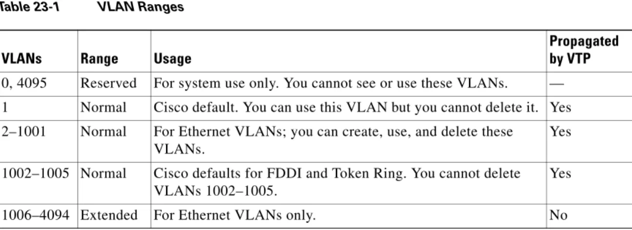
Cisco IOS Release 12.2SX supports 4096 VLANs in accordance with the IEEE 802.1Q standard. These VLANs are organized into several ranges; you use each range slightly differently. Some of these VLANs are propagated to other switches in the network when you use the VLAN Trunking Protocol (VTP). The extended-range VLANs are not propagated, so you must configure extended-range VLANs manually on each network device.
Table 23-1 describes the VLAN ranges.
The following information applies to VLAN ranges:
• Layer 3 LAN ports, WAN interfaces and subinterfaces, and some software features use internal VLANs in the extended range. You cannot use an extended range VLAN that has been allocated for internal use.
• To display the VLANs used internally, enter the show vlan internal usage command. With earlier releases, enter the show vlan internal usage and show cwan vlans commands.
• You can configure ascending internal VLAN allocation (from 1006 and up) or descending internal VLAN allocation (from 4094 and down).
• You must enable the extended system ID to use extended range VLANs (see the “Understanding the Bridge ID” section on page 28-2).
Table 23-1 VLAN Ranges
VLANs Range Usage
Propagated by VTP
0, 4095 Reserved For system use only. You cannot see or use these VLANs. —
1 Normal Cisco default. You can use this VLAN but you cannot delete it. Yes
2–1001 Normal For Ethernet VLANs; you can create, use, and delete these VLANs.
Yes
1002–1005 Normal Cisco defaults for FDDI and Token Ring. You cannot delete VLANs 1002–1005.
Yes
Chapter 23 Configuring VLANs
VLAN Configuration Guidelines and Restrictions
VLAN Configuration Guidelines and Restrictions
When creating and modifying VLANs in your network, follow these guidelines and restrictions:
• VLANs support a number of parameters that are not discussed in detail in this section. For complete information, see the Cisco IOS Master Command List publication.
• If the switch is in VTP server or transparent mode (see the “Configuring VTP” section on
page 22-10), you can configure VLANs in global and config-vlan configuration modes. When you configure VLANs in global and config-vlan configuration modes, the VLAN configuration is saved in the vlan.dat files. To display the VLAN configuration, enter the show vlan command.
If the switch is in VLAN transparent mode, use the copy running-config startup-config command to save the VLAN configuration to the startup-config file. After you save the running configuration as the startup configuration, use the show running-config and show startup-config commands to display the VLAN configuration.
• When the switch boots, if the VTP domain name and the VTP mode in the startup-config file and vlan.dat files do not match, the switch uses the configuration in the vlan.dat file.
• You can configure extended-range VLANs only in global configuration mode.
• Supervisor engine redundancy does not support nondefault VLAN data file names or locations. Do not enter the vtp filefile_name command on a switch that has a redundant supervisor engine.
• Before installing a redundant supervisor engine, enter the no vtp file command to return to the default configuration.
• Before you can create a VLAN, the switch must be in VTP server mode or VTP transparent mode. For information on configuring VTP, see Chapter 22, “Configuring VTP.”
• The VLAN configuration is stored in the vlan.dat file, which is stored in nonvolatile memory. You can cause inconsistency in the VLAN database if you manually delete the vlan.dat file. If you want to modify the VLAN configuration or VTP, use the commands described in this guide and in the Cisco IOS Master Command List, publication.
• To do a complete backup of your configuration, include the vlan.dat file in the backup.
Configuring VLANs
These sections describe how to configure VLANs:
• Configurable VLAN Parameters, page 23-4
• Ethernet VLAN Default Parameters, page 23-4
• VLAN Locking, page 23-4
• Creating or Modifying an Ethernet VLAN, page 23-5
• Assigning a Layer 2 LAN Interface to a VLAN, page 23-6
• Configuring the Internal VLAN Allocation Policy, page 23-7
• Configuring VLAN Translation, page 23-7
• Mapping 802.1Q VLANs to ISL VLANs, page 23-10
Configurable VLAN Parameters
Note • Ethernet VLAN 1 uses only default values.
• Except for the VLAN name, Ethernet VLANs 1006 through 4094 use only default values.
• You can configure the VLAN name for Ethernet VLANs 1006 through 4094.
You can configure the following parameters for VLANs 2 through 1001:
• VLAN name
• VLAN type (Ethernet, FDDI, FDDI network entity title [NET], TrBRF, or TrCRF)
• VLAN state (active or suspended)
• Security Association Identifier (SAID)
• Bridge identification number for TrBRF VLANs
• Ring number for FDDI and TrCRF VLANs
• Parent VLAN number for TrCRF VLANs
• Spanning Tree Protocol (STP) type for TrCRF VLANs
Ethernet VLAN Default Parameters
• VLAN ID: 1; range: 1–4094
• VLAN name:
– VLAN 1: “default”
– Other VLANs: “VLANvlan_ID”
• 802.10 SAID: 10vlan_ID; range: 100001–104094
• MTU size: 1500; range: 1500–18190
• Translational bridge 1: 0; range: 0–1005
• Translational bridge 2: 0; range: 0–1005
• VLAN state: active: active, suspend
• Pruning eligibility:
– VLANs 2–1001 are pruning eligible
– VLANs 1006–4094 are not pruning eligible
VLAN Locking
Release 12.2(33)SXH and later releases support the VLAN locking feature, which provides an extra level of verification to ensure that you have configured the intended VLAN.
Chapter 23 Configuring VLANs
Configuring VLANs
For additional information about how to configure access and trunk ports with VLAN locking enabled, see the “Configuring LAN Interfaces for Layer 2 Switching” section on page 17-6.
For additional information about how to configure ports in private VLANs with VLAN locking enabled, see the “Configuring Private VLANs” section on page 24-11.
By default, the VLAN locking is disabled. To enable VLAN locking, perform this task:
Creating or Modifying an Ethernet VLAN
User-configured VLANs have unique IDs from 1 to 4094, except for reserved VLANs (see Table 23-1 on page 23-2). Enter the vlan command with an unused ID to create a VLAN. Enter the vlan command for an existing VLAN to modify the VLAN (you cannot modify an existing VLAN that is being used by a Layer 3 port or a software feature).
See the “Ethernet VLAN Default Parameters” section on page 23-4 for the list of default parameters that are assigned when you create a VLAN. If you do not specify the VLAN type with the media keyword, the VLAN is an Ethernet VLAN.
To create or modify a VLAN, perform this task:
When you create or modify an Ethernet VLAN, note the following information:
• Because Layer 3 ports and some software features require internal VLANs allocated from 1006 and up, configure extended-range VLANs starting with 4094.
• You can configure extended-range VLANs only in global configuration mode. You cannot configure extended-range VLANs in VLAN database mode.
• Layer 3 ports and some software features use extended-range VLANs. If the VLAN you are trying to create or modify is being used by a Layer 3 port or a software feature, the switch displays a message and does not modify the VLAN configuration.
Command Purpose
Step 1 Router(config)# vlan port provisioning Enables VLAN locking.
Step 2 Router# show vlan port provisioning Verifies the VLAN locking status (enabled or disabled).
Command Purpose
Step 1 Router# configure terminal
or
Router# vlan database
Enters VLAN configuration mode.
Step 2 Router(config)# vlan
vlan_ID{[-vlan_ID]|[,vlan_ID]) Router(config-vlan)#
or
Router(vlan)# vlan vlan_ID
Creates or modifies an Ethernet VLAN, a range of Ethernet VLANs, or several Ethernet VLANs specified in a comma-separated list (do not enter space characters).
Step 3 Router(config-vlan)# end
or
Router(vlan)# exit
Updates the VLAN database and returns to privileged EXEC mode.
When deleting VLANs, note the following information:
• You cannot delete the default VLANs for the different media types: Ethernet VLAN 1 and FDDI or Token Ring VLANs 1002 to 1005.
• When you delete a VLAN, any LAN ports configured as access ports assigned to that VLAN become inactive. The ports remain associated with the VLAN (and inactive) until you assign them to a new VLAN.
This example shows how to create an Ethernet VLAN in global configuration mode and verify the configuration:
Router# configure terminal
Router(config)# vlan 3
Router(config-vlan)# end
Router# show vlan id 3
VLAN Name Status Ports
---- - --- ---3 VLAN000---3 active
VLAN Type SAID MTU Parent RingNo BridgeNo Stp BrdgMode Trans1 Trans2 ---- --- ---- --- -- ---- -- ---3 enet 10000---3 1500 - - - - - 0 0
Primary Secondary Type Interfaces
--- --- ---
---This example shows how to create an Ethernet VLAN in VLAN database mode:
Router# vlan database
Router(vlan)# vlan 3
VLAN 3 added: Name: VLAN0003 Router(vlan)# exit
APPLY completed. Exiting....
This example shows how to verify the configuration:
Router# show vlan name VLAN0003
VLAN Name Status Ports
---- --- --- ---3 VLAN000---3 active
VLAN Type SAID MTU Parent RingNo BridgeNo Stp Trans1 Trans2 ---- --- ---- --- -- ---- ---3 enet 10000---3 1500 - - - - 0 0 Router#
Assigning a Layer 2 LAN Interface to a VLAN
A VLAN created in a management domain remains unused until you assign one or more LAN ports to the VLAN.
Note Make sure you assign LAN ports to a VLAN of the appropriate type. Assign Ethernet ports to Ethernet-type VLANs.
Chapter 23 Configuring VLANs
Configuring VLANs
Configuring the Internal VLAN Allocation Policy
For more information about VLAN allocation, see the “VLAN Ranges” section on page 23-2.
Note The internal VLAN allocation policy is applied only following a reload.
To configure the internal VLAN allocation policy, perform this task:
When you configure the internal VLAN allocation policy, note the following information:
• Enter the ascending keyword to allocate internal VLANs from 1006 and up.
• Enter the descending keyword to allocate internal VLAN from 4094 and down. This example shows how to configure descending as the internal VLAN allocation policy:
Router# configure terminal
Router(config)# vlan internal allocation policy descending
Configuring VLAN Translation
On trunk ports, you can translate one VLAN number to another VLAN number, which transfers all traffic received in one VLAN to the other VLAN.
These sections describe VLAN translation:
• VLAN Translation Guidelines and Restrictions, page 23-8
• Configuring VLAN Translation on a Trunk Port, page 23-9
• Enabling VLAN Translation on Other Ports in a Port Group, page 23-10
Note To avoid spanning tree loops, be careful not to misconfigure the VLAN translation feature.
Command Purpose
Step 1 Router(config)# vlan internal allocation policy
{ascending | descending} Configures the internal VLAN allocation policy.
Step 2 Router(config)# end Exits configuration mode.
Step 3 Router# reload Applies the new internal VLAN allocation policy.
VLAN Translation Guidelines and Restrictions
When translating VLANs, follow these guidelines and restrictions:
• A VLAN translation configuration is inactive if it is applied to ports that are not Layer 2 trunks.
• Do not configure translation of ingress native VLAN traffic on an 802.1Q trunk. Because 802.1Q native VLAN traffic is untagged, it cannot be recognized for translation. You can translate traffic from other VLANs to the native VLAN of an 802.1Q trunk.
• Do not remove the VLAN to which you are translating from the trunk.
• The VLAN translation configuration applies to all ports in a port group. VLAN translation is disabled by default on all ports in a port group. Enable VLAN translation on ports as needed.
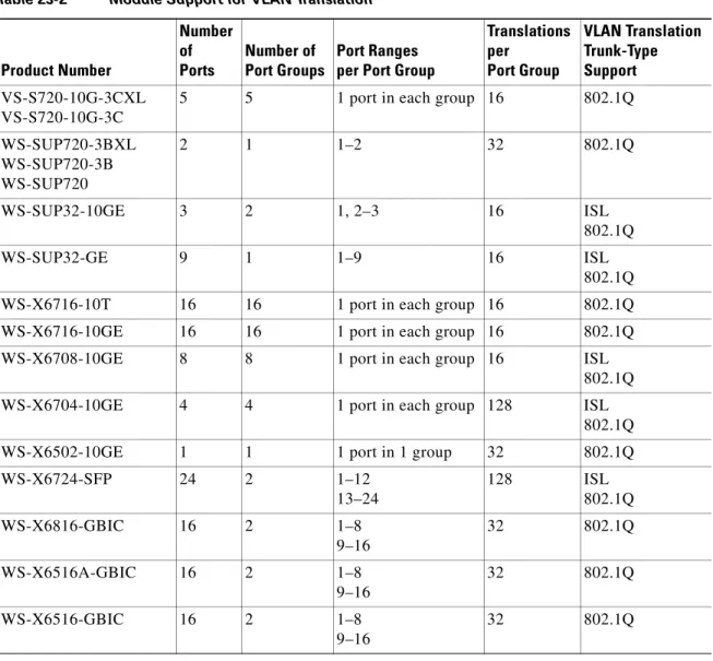
• For the modules that support VLAN translation, Table 23-2 lists: – The port groups to which VLAN translation configuration applies
– The number of VLAN translations supported by the port groups
– The trunk types supported by the modules
Table 23-2 Module Support for VLAN Translation
Product Number Number of Ports Number of Port Groups Port Ranges per Port Group
Translations per Port Group VLAN Translation Trunk-Type Support VS-S720-10G-3CXL VS-S720-10G-3C
5 5 1 port in each group 16 802.1Q
WS-SUP720-3BXL WS-SUP720-3B WS-SUP720
2 1 1–2 32 802.1Q
WS-SUP32-10GE 3 2 1, 2–3 16 ISL
802.1Q
WS-SUP32-GE 9 1 1–9 16 ISL
802.1Q
WS-X6716-10T 16 16 1 port in each group 16 802.1Q
WS-X6716-10GE 16 16 1 port in each group 16 802.1Q
WS-X6708-10GE 8 8 1 port in each group 16 ISL
802.1Q
WS-X6704-10GE 4 4 1 port in each group 128 ISL
802.1Q
WS-X6502-10GE 1 1 1 port in 1 group 32 802.1Q
WS-X6724-SFP 24 2 1–12
13–24
128 ISL
802.1Q
WS-X6816-GBIC 16 2 1–8
9–16
32 802.1Q
WS-X6516A-GBIC 16 2 1–8
9–16
32 802.1Q
WS-X6516-GBIC 16 2 1–8
9–16
Chapter 23 Configuring VLANs
Configuring VLANs
Note To configure a port as a trunk, see the “Configuring a Layer 2 Switching Port as a Trunk” section on page 17-10.
Configuring VLAN Translation on a Trunk Port
To translate VLANs on a trunk port, perform this task:
WS-X6748-GE-SFP 48 4 1–23, odd
2–24, even 25–47, odd 26–48, even
128 ISL
802.1Q
WS-X6748-GE-TX 48 4 1–12
13–24 25–36 37–48
128 ISL
802.1Q
WS-X6516-GE-TX 16 2 1–8
9–16
32 802.1Q
WS-X6524-100FX-MM 24 1 1–24 32 ISL
802.1Q
WS-X6548-RJ-45 48 1 1–48 32 ISL
802.1Q
WS-X6548-RJ-21 48 1 1–48 32 ISL
802.1Q Table 23-2 Module Support for VLAN Translation (continued)
Product Number Number of Ports Number of Port Groups Port Ranges per Port Group
Translations per Port Group VLAN Translation Trunk-Type Support Command Purpose
Step 1 Router(config)# interface type1 slot/port Selects the Layer 2 trunk port to configure.
Step 2 Router(config-if)# switchport vlan mapping enable Enables VLAN translation.
Step 3 Router(config-if)# switchport vlan mapping
original_vlan_ID translated_vlan_ID
Translates a VLAN to another VLAN. The valid range is 1 to 4094.
When you configure a VLAN mapping from the original VLAN to the translated VLAN on a port, traffic arriving on the original VLAN gets mapped or translated to the translated VLAN at the ingress of the switch port, and the traffic internally tagged with the translated VLAN gets mapped to the original VLAN before leaving the switch port. This method of VLAN mapping is a two-way mapping.
Step 4 Router(config-if)# end Exits configuration mode.
Step 5 Router# show interface type1 slot/port vlan mapping
This example shows how to map VLAN 1649 to VLAN 755 Gigabit Ethernet port 5/2:
Router# configure terminal
Router(config)# interface gigabitethernet 5/2
Router(config-if)# switchport vlan mapping 1649 755
Router(config-if)# end
Router#
This example shows how to verify the configuration:
Router# show interface gigabitethernet 5/2 vlan mapping
State: enabled
Original VLAN Translated VLAN --- 1649 755
Enabling VLAN Translation on Other Ports in a Port Group
To enable VLAN translation on other ports in a port group, perform this task:
This example shows how to enable VLAN translation on a port:
Router# configure terminal
Router(config)# interface gigabitethernet 5/2
Router(config-if)# switchport vlan mapping enable
Router(config-if)# end
Router#
Mapping 802.1Q VLANs to ISL VLANs
The valid range of user-configurable ISL VLANs is 1 through 1001 and 1006 through 4094. The valid range of VLANs specified in the IEEE 802.1Q standard is 1 to 4094. You can map 802.1Q VLAN numbers to ISL VLAN numbers.
802.1Q VLANs in the range 1 through 1001 and 1006 through 4094 are automatically mapped to the corresponding ISL VLAN. 802.1Q VLAN numbers corresponding to reserved VLAN numbers must be mapped to an ISL VLAN in order to be recognized and forwarded by Cisco network devices.
These restrictions apply when mapping 802.1Q VLANs to ISL VLANs:
• You can configure up to eight 802.1Q-to-ISL VLAN mappings.
• You can only map 802.1Q VLANs to Ethernet-type ISL VLANs.
• Do not enter the native VLAN of any 802.1Q trunk in the mapping table.
1. type = fastethernet, gigabitethernet, or tengigabitethernet
Command Purpose
Step 1 Router(config)# interface type1 slot/port
1. type = fastethernet, gigabitethernet, or tengigabitethernet
Selects the LAN port to configure.
Step 2 Router(config-if)# switchport vlan mapping enable Enables VLAN translation.
Step 3 Router(config-if)# end Exits configuration mode.
Step 4 Router# show interface type1 slot/port vlan mapping
Chapter 23 Configuring VLANs
Configuring VLANs
• When you map an 802.1Q VLAN to an ISL VLAN, traffic on the 802.1Q VLAN corresponding to the mapped ISL VLAN is blocked. For example, if you map 802.1Q VLAN 1007 to ISL VLAN 200, traffic on 802.1Q VLAN 200 is blocked.
• VLAN mappings are local to each switch. Make sure that you configure the same VLAN mappings on all appropriate network devices.
To map an 802.1Q VLAN to an ISL VLAN, perform this task:
This example shows how to map 802.1Q VLAN 1003 to ISL VLAN 200:
Router# configure terminal
Router(config)# vlan mapping dot1q 1003 isl 200
Router(config)# end
Router#
This example shows how to verify the configuration:
Router# show vlan
<...output truncated...> 802.1Q Trunk Remapped VLANs: 802.1Q VLAN ISL VLAN 1003 200
Saving VLAN Information
The VLAN database is stored in the vlan.dat file. You should create a backup of the vlan.dat file in addition to backing up the running-config and startup-config files. If you replace the existing supervisor engine, copy the startup-config file as well as the vlan.dat file to restore the system. The vlan.dat file is read on bootup and you will have to reload the supervisor engine after uploading the file. To view the file location, use the dir vlan.dat command. To copy the file (binary), use the copy vlan.dat tftp
command.
Tip For additional information about Cisco Catalyst 6500 Series Switches (including configuration examples and troubleshooting information), see the documents listed on this page:
http://www.cisco.com/en/US/products/hw/switches/ps708/tsd_products_support_series_home.html
Participate in the Technical Documentation Ideas forum
Command Purpose
Step 1 Router(config)# vlan mapping dot1q dot1q_vlan_ID
isl isl_vlan_ID
Maps an 802.1Q VLAN to an ISL Ethernet VLAN. The valid range for dot1q_vlan_ID is 1001 to 4094. The valid range for isl_vlan_ID is the same.
Step 2 Router(config)# end Exits configuration mode.