Vol. 6, No. 10, 2015
Design of Socket Based on Intelligent Control and
Energy Management
Jiang Feng
School of Electronic and Electrical Engineering Shanghai University of Engineering Science
Shanghai, China
Wu Fei*
School of Electronic and Electrical Engineering Shanghai University of Engineering Science
Shanghai, China
Dai Jian
School of Electronic and Electrical Engineering Shanghai University of Engineering Science
Shanghai, China
Zou Yan
School of Electronic and Electrical Engineering Shanghai University of Engineering Science
Shanghai, China
Abstract—Smart home is one of the main applications of internet of things, and it will realize the intellectualization of household. Smart socket is part of the smart home, which can be controlled remotely by power supplied, monitor utilization condition, communication network and other functions. This article mainly introduces the intelligent electrical outlet of each hardware modules; software part mainly analyzes the socket’s communication mechanism, and the electricity consumption of collected power statistics through diagrams to feedback through wireless communication. Things achieved in an environment of communication between the user and the smart power outlet timely feedback to the user, so as to achieve energy-saving purposes.
Keywords—Internet of things; Smart home; Intelligent electrical outlet; Wireless communication; Power statistics
I. INTRODUCTION
The fast development of electrical makes our lives become more and more convenient. Social demand for power supply capacity is becoming more and more strictly. On one hand is how to save power; On the other hand is how to meet the need of the society of electricity [1],this area has being one of the most intractable problem throughout the world, under the environment of internet of things intelligent socket realizes to consume capacity and feedback to the client's function timely.
Functions and designing method of every module are introduced in this article in detail. Intelligent electrical outlet is an important part of intelligent household system, it can realize the power equipment monitoring easily, control and transmit data, communication technology uses the WIFI wireless technology; the technology is very suitable for household system communication network [2]. Intelligent socket of the original concept is for the purpose of security and protection, it is on the basis of ordinary socket extending more functions, such as its several protection functions against short circuit, overvoltage and lightning. Now smart socket is on the basis of these features combined with the functions of control circuit remotely, and the statistical power of connection on the socket device, through the network it will transmit the data to the users, this data provides a basis for
users make decisions wisely, it will make appliances become more intelligent eventually.
Intelligent socket sets WIFI module internally [3], the client that can perform such operations on an ordinary smart phone through the socket. Through intelligent control can switch implement control other switch remotely, operation results will also return to the remote control. It plays a switch setting’s role. Intelligent socket mainly is used for household intelligent functions, it often matches with other electrical appliances. Intelligent sockets [4] can open circuit power supply, so as to control the electrical power supply or not; And intelligent host to communicate with each other to ensure the smart home system work normally. Some of the applications build on real time utility data will serve to user; others will analyze data in aggregate and serve policy and other decision makers. As a device can switch power supply of smart home, intelligent electrical outlet is the main medium of the future smart home life. Intelligent home has emerged with the development of computer science, communications, network and automatic control technology and so on[5]. It is also a great change brought up by advancement of technology.
II. INTELLIGENT SOCKET HARDWARE STRUCTURE
A. Framework of Design
The internal structure of the socket mainly includes MCU, WIFI communication equipment, memory ,relays, electric measurement module, keys, voltage conversion circuit, protect circuit, the power input port and the power supply output pin, which is shown in Fig.1.The following picture presents the links between the related modules. The core is STM32, which will introduced detailed in the following article.
B. The microprocessor section
Fig. 1. The Global Structure Of Intelligent Socket
Fig. 2. Part Of The MCU Diagram
To facilitate the observation, a tie-style LED indicator shows the usage status. The circuit diagram is show as Fig.3.
Fig. 3. A Tie-style LED Indicator
The system power supply indicator light is PWR, its light is blue.LED0, and LED1 are connected with PA8 and PD2 respectively. The USB serial port, USB, power supply part of the circuit diagram is shown as the Fig.4.
Fig.4. shows this circuit through the RST and DTR to control BOOT0 and RESET signal, so as to achieve a key download function modules. This section also has switch BUTTON, which is used to control the power of the whole system, if it is disconnected, the whole 3.3 V part of the system will be power outages. And the part 5V power supply is still open. It is shown in Fig.4. F1 is considered as recoverable fuse, for protecting the USB.
Fig. 4. The System Power Supply Indicator Light
C. WIFI wireless communication section
Based on the design requirements of master controller, we choose the USR-WIFI232—C322 chip [6] to realize hardware design together with other peripheral circuit, it also can use other chips and circuit to realize the WIFI communications functions. The main function is to realize the WIFI communication, to communicate with the MCU on data collection. The circuit diagram is shown in the Fig.5 below.
Fig. 5. WIFI Wireless Communication Circuit
D. Memory module
The memory may store WIFI parameters and other data for storage, and sequences of instructions that are performed by the CPU, or any other device are included in the computing system. The storage parameters including WIFI wireless network mode, the connection of the router network name, password, selection of WIFI network IP address, destination IP address, etc.
VBAT1 PC13/ANT12 PC14/OSC323 PC15/OSC324 PD0/OSCIN5 PD1/OSCOUT6 NRST7 PC0/ADC108 PC1/ADC119 PC2/ADC1210 PC3/ADC1311 VSSA12 VDDA13 PA0/WKUP/ADC0/TIM2_CH1_ETR14 PA1/ADC1/TIM2_CH215 PA2/U2_TX/ADC2/TIM2_CH316 PA3/U2_RX/ADC3/TIM2_CH417 VSS18 VDD19 PA4/SPI1_NSS/ADC420 PA5/SPI1_SCK/ADC521 PA6/SPI1_MISO/ADC6/TIM3_CH122 PA7/SPI1_MOSI/ADC7/TIM3_CH223 PC4/ADC1424 PC5/ADC1525 PB0/ADC8/TIM3_CH326 PB1/ADC9/TIM3_CH427 PB2/BOOT128 PB10/I2C2_SCL/U3_TX29 PB11/I2C2_SDA/U3-RX30 VSS31
VDD32 PB12/SPI2 NSS/I2C2 SMBAI/TIM1 BKIN33
PB13/SPI2_SCK/TIM1_CH1N34 PB14/SPI2_MISO/TIM1_CH2N35 PB15/SPI2_MOSITIM1_CH3N36 PC637 PC738 PC839 PC940 PA8/TIM1_CH1/MCO41 PA9/UI_TX/TIM1_CH242 PA10/UI_RX/TIM1_CH343 PA11/CAN_RX/USBDM/TIM1_CH444 PA12/CAN_TX/USBDP/TIM1_ETR45 PA13/JTMS/SWDIO46 VSS47 VDD48 PA14/JTCK/SWCLK49 PA15/JTDI50 PC1051 PC1152 PC1253 PD2/TIM3_ETR54 PB3/JTDO/TRACESWO55 PB4/JNTRST56 PB5/I2C1_SMBAI57 PB6/I2C1_SCL/TIM4_CH158 PB7/I2C1_SDA/TIM4_CH259 BOOT060 PB8/TIM4_CH361 PB9/TIM4_CH462 VSS63 VDD64 *STM32F103RBT6 C410 R41M 1 2 3 4 5 6 BOOTHeader 3X2 1 2 3 4 5 6 7 8 9 10 11 12 13 14 15 16 P3Header 16 1 2 P4 BATI RESET 1 2
Y1 32.768k
VCC3.3 R1100K R2100K GND BOOT0BOOT1 D? D? VCC3.3 GND C4100nF R410K VCC3.3 RESET PC13 C410 1 2 8MHZ 100nF 100nF C410uF C410uF R1100K VCC3.3 GND RESETPC0PC1PC2PC3PA0PA1PA2PA3 C4104 GNDVCC3.3 C4104 GNDVCC3.3 PA4PA5PA6PA7PC4PC5PB0PB1PB2PB10PB11 RXDTXD PA0PA1PA2PA3PA4PA5PA6PA7PA8PA9PA10PA11PA12PA13PA14PA15 C4104 VCC3.3 GND PB9PB8BOOT0PB12PB13PB14PB15PC6PC7PC8PC9PA8PA9PA10PA11PA12PA13 C4104 GNDVCC3.3PA14PA15PC10PC11PC12PD2PB3PB4PB5PB6PB7 U1_TXDU1_RXD LED0 LED1 VCC3.3 R21 100k LED R22 100k LED DS0 DS1 R22 100k LED PWR LED0 LED1 GND TXD 1 DTR_N 2 RTS_N 3 VDD_232 4 RXD 5 RI_N 6 GND 7 VDD 8 DSR_N 9 DCD_N 10 CTS_N 11 SHTD_N 12 EE_CLK 13 DATA 14 DP 15 DM 16 VDD_3V3 17 GND_3V3 18 RESET 19 VDD 20 GND 21 TRI_MODE 22 LD_MODE 23 VDD_PLL 24 GND_PLL 25 PLL_TEST 26 OSC1 27 OSC2 28 * R21 1K R21 1K R21 1K R21 1K Q1 Q2 TXD RESET BOOT0 VCC3.3 C2 10uF GND 3V3 RXD C2 10uF GND VCC5 10uF C2 10uF C2 10uF 1 2 Y3 VCC5 R21 45K VCC5 VCC5 3V3 GND PL2302 D-PL2302 D+
1 3 5 2 4 6
1 3 5 2 4 6
Vol. 6, No. 10, 2015
After the socket makes connection, MCU reads the parameters from memory [7], it will control WIFI to generate WIFI network automatically or connect with a router. MCU reads target parameter information from memory, this system call through WIFI devices to send control code and other data to a specified device.
E. Relay module
The Relay connect with the MCU's GPIO port by triode [8], MCU controls relay on or off through the output of the GPIO port, which is shown in Fig.6.
Fig. 6. Relay module
Power supply is available only when the relays are connected. At the same time, on the connect circuit between the relay and triode parallel a led, acting on the indicator. A lighted LED indicates a working relay, however flickers with any activity. It can control socket on or off through STM32 control relays.
F. Power Measurement System
It will inevitably contain many sensor modules inside the hardware during intelligent home appliance. The power energy metering module acts as a sensor. It becomes one of the fundamental sensors during many sensors in the home appliance, the following parameters are measured: voltage, current, power factor, power, reactive power and apparent power [9].
Electricity metering module [10] is mainly be composed of a set of EEM301 modules, when the socket is connected, it can realize the inspection of the values about the output current and voltage from the socket, and the results will be sent to the MCU. Electric power management is very necessary, we don't use the simple way of calculation about power is multiplied by the time, which choose the level metering chip, it can satisfy the precision of electricity measurement requirements.
On this part we use EEM301 module for the intelligent power acquisition, it is applied to the smart home, for collecting the electrical power consumption, real-time power, real-time voltage, current, and it can connect WIFI, wireless communication modules by UART, SPI and other wireless communication modules. Users can remote monitor the home appliances by visit the WEB server. So it achieves the remote monitor and intelligent purpose.
In the part of hardware design, voltage and current sampling, the power supply circuit design, circuit communication that is designed. The circuit schematic diagram of the power supply is designed as the Fig.7.Power supply is based on LD0 chips, and takes the form of diode M7 as the protection circuits. By employing the designs, the reliability of the over-voltage protection circuit, the source, the source system, the electronic device is improved.
Fig. 7. Circuit Schematic Diagram Of The Power Supply
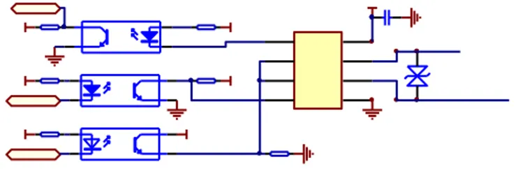
485 communication circuits use the technique of optical coupling isolation within the input, output and power supply module. From the design of hardware, the power supply is isolated, its requirements is simple, the light coupling communication interface can be directly connected with the TXD , RXD, RD pins in EEM301,in this paper we adopted the following circuit is shown in the Fig.8[11].
Fig. 8. 485 communication circuit
The current and voltage detection are adopted resistance of sampling and current transformer sampling mode.
G. The key module
Key's main function is reset the socket or restore the factory settings. While the push-button is pressed less than 3 seconds, the system will reset when the socket is released then all devices will restart. While the push-button is pressed more than 3 seconds, the outlet will restore the factory default settings. To reset the socket, it will not affect the socket's runtime patterns, connecting network name, password, IP address etc., only to restart; To restore the factory default settings, the socket outlet will work in router mode [12], the socket will generate a WIFI network automatically, through the process of the client it can be connect to the Internet, and it also can set the socket parameters.
H. Other modules
Protection circuit is mainly be made of resistance and fuse. When the current is larger than the rated current, the fuse will disconnect automatically in order to ensure safety. If the voltage turns to unwanted fluctuations, and the transient voltage is greater than the specified voltage, through the resistance’s short circuit effect, it will force fuse disconnected to ensure the safety of electricity.
D2
LED1
K?
Relay-SPDT
1K R1
D1
LED0
VCC5
Q?
2N3904
GPIO?
GND
D?
Diode
VCC5
1K R1
GND
1K R1
VCC5
VCC12
GND
M1
M7
VCC24
C1
25V/22UF
VCC50
GND
OUT
3
IN
1
2
GND
U1
7806
GND
C2 106
R
1
/RE
2
DE
3
D
4
GND
5
A
6
B
7
VCC
8
U3
Nonpolarity-485
V485
TVS
P6KE6.8CA
V485
V485
R5
510
R7
510
OP4
NEC2501
OP5
NEC2501
R4
510
OP6 NEC2501
R6
510
R9
10k
V485
485GND
R8
510
485GND
485COMM-2
RXD4852
TXD4852
CON4852
485GND
VCC
VCC
VCC
485A
485B
C3
106
The power input ports are terminal blocks, for connecting wire, zero line and the ground respectively.PE or PEN line are not allowed to connect in series between sockets.
III. THE SOFTWARE DESIGN OF THE SYSTEM
The intelligent socket's essence is the socket as a carrier, and it accomplishes a remote smart home system through WIFI wireless [13].That is to say, If we have a super smart socket, no matter where we go, we can control the home air conditioning, lights, television and other household appliances just only with the phone, and we also can realize monitoring of family power and getting its analysis table.
A. The main program flow
The purpose of designing of the system software [8]that is the server mainly be responsible for receiving a serial data from the port, after parsing, according to the inventory build listening socket, the client connection is accepted, maintain the client socket connection, At the same time it will send the received binary data stream to the client. Client application then launches three threads, including connection thread, receiving data thread, data processing thread which they will complete the functions such as data receiving and parsing, displaying and so on.
Fig. 9. The physics topology structure between the communication server and its clients
Client applications send a connection request to the server, after setting up the connection the client will send request to the server for reading data, the server processes the request and sends data, the client then starts the corresponding thread for processing. The server establishes TCP/IP connection [14] with MCU firstly, then starts receiving data thread, being responsible for receiving the corresponding data; once the thread has processed the data and displayed then stored it in the database server. To monitor the client connection thread, it is responsible for establishing user socket and listening socket connection.
The system uses the way to connect client applications to the server even in the face of application, platform or network failure. Once a connection is successfully made, the next task often is to read the data thread, read correspondent datum from the buffer, then write the information to a table, avoid the loss of data. View and update data for tables and views: Show as well as update data for tables and views [15].
B. Specific details
For the serial port settings section, first of all, we need to make the serial clock can be set, in APB2ENR registers' configure the serial port 1.Then configure a serial port baud rate in USART_BRR registers. After then, we can go on serial port controlling on the USART_CR1 register. Then in the USART_DR register, data can be sent and received. Of course, a serial port state of nature can be read by USART_SR register.
C. The specific process
After initialing the server which will send out the radio instruction via a serial port at regular intervals, the received instruction socket will reply their own media access control (MAC) addresses to the server.
In general, the server will decode after receiving the response of the frame socket. If the server received the socket for radio command response frame, then obtained the MAC address of the socket [16], and read the output socket's order through a serial port, got the socket’s power information instruction, after receiving the order, then it would send the response frame of power information to the server.
D. The design of the PC client software
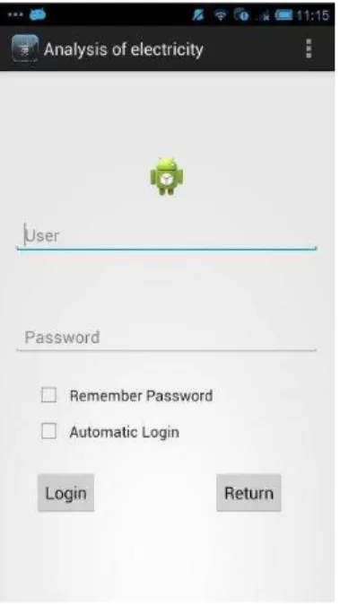
The PC client authentication information is divided into three parts, they are user login interface, electricity information query interface, and actual data generated interface. This system establishes log-in boundary wish to realize the identification [17].It is shown in Fig.10.
Fig. 10.User login interface
Before being activated, the software read the information of interface elements, and generate graphical user interface (GUI) dynamically according to the information.
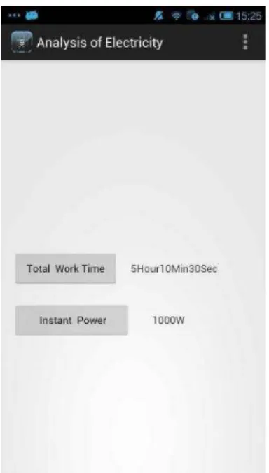
The socket's equipment interface can add or delete a socket for users, and it also can control the state of the socket whether open or not. The electricity information that will be displayed in the Fig.11.Show the real-time electrical appliances [18].
Vol. 6, No. 10, 2015
Fig. 11.The real-time electrical information
Fig. 12.The real-time electrical appliances
First, Users can accomplish logging the system remotely, and they can view the device’s current work status, ultimately the client will allow the electricity used by domestic appliances to be "dynamically" managed .This design reduces the waste of electricity by users. This will alert users track how much energy each appliance is using and command it to use less. This will alert the user to use a power saving device, so get rid of some bad habits of electricity or energy-consuming devices can be replaced with energy-saving equipment according to the situation.
E. The software design of the intelligent mobile terminal
The major implementation of the smart phone terminal interface is showing the electricity situation, and electrical function. The Intelligent mobile terminally connect to the web
an XML aware static reporting program can read that data directly. And it is displayed on the phone’s screen of the result. The users can control the condition of the sockets and devices through the electric state interface. And it also can control the opening and closing of the corresponding socket [20].
IV. CONCLUSION
The automatic control system realizes the automatic control for intelligent electrical outlet by WIFI wireless communication technology and Internet technology. The system has much advantages in reliability and performance, It will better realize the automation and intelligent in control process.
The next further job mainly realizes the intelligent socket all the way of timing control, it also can add a leakage protection switch to regular socket, eventually it will be able to make it more practical by analyzing and improving them. Later, we can add an LED display in the smart socket further, it can make convenient for users to intuitive interact and experience intuitively. So as to solve a common problem the current socket owned: the user does not know what the current state of the socket presently. However the display screen can solve this problem. Of course, on the other hand intelligent socket also need to keep the traditional control mode, so that the user can according to own needs to choose whether to let it "smart".
ACKNOWLEDGMENT
This work was supported by the National Natural Science Foundation of China (No.61272097, 61405045), the Shanghai Municipal Committee of Science and Technology Project (No.13510501400), Shanghai Municipal Education Commission, A Key Innovation Project (No.12ZZ182).
REFERENCES
[1] Chen Hai Wang, Zhen Juan Zhang, Ming Huang. The design of the wireless intelligent socket system in the smart home. Journal of TV Technology, vol.37 (2013):80-83.
[2] Yi chao Jin, Lijuan Sun, Ruchuan Wang. The design of the intelligent electrical outlet in Internet environment. The 4th China sensor network academic conference proceedings in CWSN2010.pp.321-326, 2013. [3] Yichao Jin, Lijuan Sun, Runchuan Wang. The design of the intelligent
electrical outlet in Internet environment. Journal of Research and development of Computing machine, vol.47(2010):321-326.
[4] Jin Wang. Research of wireless digital home networks. Xi AN Northwestern university,2010.
[5] Wei Xu, Yuanjian Jiang, Bin Wang. Application of ZigBee technology in the intelligent electrical outlet design. Journal of Communication of Power System,vol.32(2011):78-81.
[6] Fangrong Xu. Design of Wireless Intelligent Home Control System. Journal of Modern architecture electrical, vol,1,2010.
[7] Xianchang Min, Lican Huang. Research of Web service technology based based on the Android platform. Journal of Industrial Control Computer,vol.24(2011):92-94.
[8] Jinhua Peng, Shaolong Shu, Feng Lin, Zhiqiang Huang. A review of several studies on the Home energy management system. Journal of Management of Power demand side,vol.13(2011):35-38.
[10] Han J,Choi CS,Lee I.More efficient home energy management system based on Zigbee communication and infrared remote controls[J].IEEE Transactions on Consumer Electronics, 2011,57(1):85-89.
[11] Wenxuan Yao, Zhaosheng Teng, Jingwen Xiong, Yuanning Deng,Tan Xia.Design of Multi-functional intelligent socket. Journal of Technology development,vol.29(2010):28-30.
[12] Huifang Sun, Chundong Mo. Design and implementation of smart home system based on the STM32.Journal of Electronic design engineering,vol.22(2014):82-85.
[13] Shuihong Wang, Wei Xu, Liping Hao.STM32 series ARM Cortex-M3 microcontroller principle and practice.BeiJing:Beijing University Of Aeronautics And Astronautics Press,2008.
[14] Yuesheng Xiang, Duanxia Gao, Yangbo Wu.The design and implementation of intelligent socket based on single chip microcomputer. Journal of Industrial control computer, vol.25(2012):129-131.
[15] Xiaofeng Yao, Chunguang Zhang. The application and JAVA implementation of Socket programming technology in embedded gateway development, Journal of Industrial control computer, pp.21-22,2006.
[16] Fischer C.Feedback on household electricity consumption: a tool for saving energy[J].Energy efficiency,2008,1(1):79-1104.
[17] Lien C H,Bai Y W,Lin M B.Remote-controllable power outlet system for home power management. Consumer Electronics,IEEE Transactions on,2007,53(4):1634-1641.
[18] SAMEK M.Practical statecharts in C/C++:quantum programming for embedded system. Florida:CRC Press,2002.
[19] Chang H H,Lin C L,Lee J K.Load identification in nonintrusive load monitoring using steady - state and turn - on transient energy algorithms[C]//2010 14th International Conference on Computer