Guilherme Alexandre Rolo
Licenciado em Ciências da Engenharia Eletrotécnica e de Computadores
Improve the Performance of Industrial Agents
using Fog Computing
Dissertação para obtenção do Grau de Mestre em
Engenharia Eletrotécnica e de Computadores
Orientador: José António Barata de Oliveira, Professor Doutor, Universidade Nova de Lisboa
Co-orientador: André Dionísio Rocha, Doutor, CTS-UNINOVA
Júri
Presidente: Prof. Doutor João Carlos da Palma Goes
Arguente: Doutor Ricardo Alexandre Fernandes da Silva Peres Vogal: Prof. Doutor José António Barata de Oliveira
Improve the Performance of Industrial Agents using Fog Computing
Copyright © Guilherme Alexandre Rolo, Faculty of Sciences and Technology, NOVA Uni-versity Lisbon.
The Faculty of Sciences and Technology and the NOVA University Lisbon have the right, perpetual and without geographical boundaries, to file and publish this dissertation through printed copies reproduced on paper or on digital form, or by any other means known or that may be invented, and to disseminate through scientific repositories and admit its copying and distribution for non-commercial, educational or research purposes, as long as credit is given to the author and editor.
"Change is the law of life. And those who look only to the past or present are certain to miss the future."
Ac k n o w l e d g e m e n t s
The conclusion of this project makes me achieve a personal milestone that is very impor-tant for my future.
I would like to thank Professor José Barata for giving me the chance of working with such equipment and develop the project at my own pace.
I would like to thank Dr. André Rocha for helping me throughout the whole project, taking his time to guide me even if it meant staying after hours. I hold nothing but a deep respect for the devotion shown on teaching and guiding.
I would like to thank all the colleagues in the research centre for their helpful insights. To my friends, Gonçalo Biscaia and Bruno Ameixieiro, for all these years in University and for all we’ve been through. It would have been a long way without you. Thank you.
A b s t r a c t
In the last decade, the market requirements have been increasing by demanding numerous different products being highly customizable. Given this need, the necessity for dynamic and flexible production lines are a high priority to meet this change.
A traditional approach is not enough to meet the market demand and due to this, several paradigms have been coined out to try and solve this problem. The proposed approach is related to communication between the shop-floor modules in order to create different products.
This work proposes an architecture where an integration layer will join a Multiagent System capable of the more recent production paradigms with legacy hardware that is present in the more traditional factories in order to have different products being produced in the same production line.
This architecture that revolves an interface that can be used by the agents in the factory in order to use the hardware modules to create a different product if need be. The main features of this project is the fact that by using datamodels and an interface created, it can be easily plugged new stations with different tools to modify the product thus increasing the amount of products that can be created.
Keywords: MultiAgent Production System, Flexible Manufacturing, Production, Integra-tion.
R e s u m o
Na última década, as exigências do mercado têm vindo a aumentar pela procura crescente de diferente tipos de produto altamente costumizáveis. Dado isto, a necessidade de criar linhas de produção dinâmicas e flexíveis são de grande prioridade.
Uma abordagem tradicional não é suficiente para satisfazer a pressão do mercado. De-vido a isto, vários paradigmas de produção industrial foram criados para tentar resolver este problema. A abordagem proposta é relacionada com a comunicação entre os módulos do chão-de-fábrica para criar produtos diferentes.
Este trabalho propõe uma arquitetura onde uma camada de integração irá juntar um sistema de multiagentes capaz de executar os mais recentes paradigmas de produção industrial com hardware legacy que está presente nas fábricas tradicionais para que se possa ter vários tipos de produtos diferentes a serem produzidos.
Esta arquitetura gira em torno de uma interface que pode ser usada pelos agentes na fábrica para que possam usar os modulos do hardware criar diferentes tipos de produto se necessário. As principais características deste projeto é o uso de modelos de dados e uma interface para poder acoplar novos estações com ferramentas diferentes para poder modificar o produto e assim aumentar o número de produtos que podem ser criados na fábrica.
Palavras-chave: Sistemas multiagente de produção, Manufatura flexível, Produção, Inte-gração.
C o n t e n t s
List of Figures xv
List of Tables xvii
Listings xix
Acronyms xxi
1 Introduction 1
1.1 Research question and hypothesis . . . 2
1.2 Work overview . . . 2
1.3 Contribution . . . 2
1.4 Thesis outline . . . 2
2 Literature Review 5 2.1 The fourth industrial revolution . . . 5
2.2 Cyber-Physical Production Systems . . . 6
2.3 Emergent Production Paradigms . . . 9
2.3.1 Flexible Manufacturing Systems . . . 9
2.3.2 Bionic Manufacturing Systems . . . 9
2.3.3 Holonic Manufacturing Systems . . . 10
2.3.4 Reconfigurable Manufacturing Systems . . . 13
2.3.5 Evolvable Production Systems . . . 13
2.4 General Conclusions . . . 16 3 Supporting Concepts 17 3.1 Cloud Manufacturing . . . 17 3.2 Fog Computing . . . 19 3.3 Multiagent Systems . . . 20 3.4 Industrial Protocols . . . 23 3.4.1 OPC-UA . . . 23
3.4.2 Data Distribution Service (DDS) . . . 25
C O N T E N T S
4 Architecture 27
4.1 MultiAgent Architecture . . . 28
4.1.1 Concept of skill . . . 32
4.1.2 Data model . . . 32
4.1.3 Interactions among agents. . . 33
4.2 Edge Level . . . 36
4.3 Integration Layer . . . 37
4.3.1 The full routine . . . 38
5 Implementation 41 5.1 Edge Level Implementation . . . 41
5.2 Multiagent Level Implementation . . . 44
5.2.1 Transporter Agent . . . 45
5.2.2 Product Agent . . . 46
5.2.3 Resource Agent . . . 49
5.2.4 Integration Layer implementation . . . 53
6 Results 57 6.1 The Industrial factory model . . . 57
6.1.1 Factory integration Layer . . . 60
6.2 Assessing the Results . . . 63
7 Conclusion and future work 75 7.1 Conclusions . . . 75
7.2 Future work . . . 76
Bibliography 77
L i s t o f F i g u r e s
2.1 Evolution of industrial revolutions.[1] . . . 6
2.2 The three main characteristics of a CPPS.[8] . . . 7
2.3 Reference Architecture Model for Industrie 4.0. [10] . . . 8
2.4 PROSA: reference architecture.[20] . . . 10
2.5 The four phases of an EPS.[30] . . . 14
3.1 Research topics on cloud manufacturing.[36] . . . 18
3.2 Fog computing architecture.[38] . . . 19
3.3 OPC-UA building blocks(on the right) relation to the interoperability layers of RAMI4.0(on the left).[48] . . . 25
4.1 Thesis’ architecture. . . 28
4.2 Transporter Agent’s behaviour. . . 29
4.3 Resource Agent’s behaviour. . . 30
4.4 Product Agent’s behaviour. . . 31
4.5 Entities present in the architecture. . . 33
4.6 Architecture data model. . . 33
4.7 Interaction between transporters to ensure the safety of the system. . . 34
4.8 Agent interactions. . . 35
4.9 Integration layer interactions. . . 37
4.10 Integration Layer flowchart. . . 38
4.11 Scheme summarising the factory’s routine. . . 39
4.12 Flow chart of the factory routine from the launch to the ending of a PA. . . . 40
5.1 Master digital inputs. . . 41
5.2 The device tree in CodeSys IDE. . . 42
5.3 Flowchart representing the edge level algorithms. . . 43
5.4 Diagram of the TA’s communication. . . 45
5.5 Diagram of the contract net protocol. . . 47
5.6 Diagram of the communication between the PA and TA. . . 48
5.7 Diagram of the communication between the PA and RA. . . 48
5.8 Diagram of the communication between all agents to execute a skill. . . 50
L i s t o f F i g u r e s
5.10 Methods available through the integration layer. . . 53
5.11 Flowchart of the Integration Layer. . . 55
6.1 Industrial factory model. . . 57
6.2 Factory’s map. . . 58
6.3 Data model instances which are launched via the DA. . . 59
6.4 User Interface to select the type of product to be produced. . . 59
6.5 Factory specific integration layer. . . 61
6.6 Confirmation interface. . . 62
6.7 Entry skill execution time. . . 63
6.8 Entry skill dispersion graph. . . 64
6.9 WeldA execution time. . . 64
6.10 WeldA skill dispersion graph. . . 65
6.11 WeldB execution time. . . 65
6.12 WeldB skill dispersion graph. . . 66
6.13 Exit skill execution time. . . 66
6.14 Exit skill dispersion graph. . . 67
6.15 TransporterB execution time. . . 67
6.16 TransporterB dispersion graph. . . 68
6.17 TransporterC execution time. . . 68
6.18 TransporterC dispersion graph. . . 69
6.19 TransporterD execution time. . . 69
6.20 TransporterD dispersion graph. . . 70
6.21 TransporterD back to TransporterC execution time. . . 70
6.22 TransporterD back to TransporterC dispersion graph. . . 71
6.23 TransporterE execution time. . . 71
6.24 TransporterE dispersion graph. . . 72
L i s t o f Ta b l e s
4.1 The system’s agents and their role. . . 32
6.1 Agents that are connected to the controller. . . 59
6.2 Products and the skills they have to consume. . . 60
L i s t i n g s
5.1 Next Skill to be executed pseudo code . . . 46 5.2 Skill to be executed . . . 49
Ac r o n y m s
ASk Atomic Skills.
BMS Bionic Manufacturing Systems.
CFP Call for Proposals.
CLA Coalition Leader Agent.
CMfg Cloud Manufacturing.
CPPS Cyber Physical Production Systems.
CPS Cyber Physical Systems.
CSk Complex Skills.
DA Deployment Agent.
DDS Data Distribution Service.
DF Directory Facilitator.
EPS Evolvable Production Systems.
FIPA Foundation for Intelligent Physical Agents.
FMS Flexible Manufacturing Systems.
AC R O N Y M S
I4.0 Industry 4.0.
ICT Information and Communication Technologies.
IoT Internet of Things.
MA Mechatronic Agent.
MAS Multiagent Systems.
MRA Manufacturing Resource Agent.
PA Product Agent.
RA Resource Agent.
RAMI4.0 Reference Architecture Model 4.0.
RMS Reconfigurable Manufacturing Systems.
ST Structured Text.
TA Transporter Agent.
C
h
a
p
t
e
r
1
I n t r o d u c t i o n
At the beginning of the industrial production, there were very few models and thus the factories did not have to adapt to change since it was easier to just have different lines on the shop-floor creating different models.
Over time, with the increase need of customised and the huge quantity that it was demanded, each model had to have very different characteristics. This change came due to the amount of products that could be chosen by the customer.
Given the constant change on products being produced and the amount being pro-duced, there was the need to create a product that was flexible and dynamic.
With the traditional approach, the shop-floors became obsolete and unable to cope with this new reality. This led to having different paradigms being proposed to meet these needs and evolve the factory to something that would fit the needs and desires of the client.
A lot of different approaches were suggested, some more subtle and some very evolu-tionary. These new approaches were suggested to the use of Information and Communi-cation Technology (ICT) in the Industry.
In this architecture, on the top side, lies the Multiagent system where the means of transporting the products are abstracted as well as the skills that will be executed. The information regarding the product is exchanged between these abstractions. Whenever a new product is launched, it will communicate with the rest of the agents which skills it wants to have executed, after this communication, the agents will sort themselves and move the product accordingly. On the bottom side of the layer architecture lies the edge level, in this level the hardware was programmed in modules so that the agents in the multiagent level can access it without running the whole code. This is done through the Integration layer. This layer main purpose is to bridge the gap between those two layers, enabling their communication. Through this, it also bridges the gap between the
C H A P T E R 1 . I N T R O D U C T I O N
emergent production paradigms and legacy hardware.
1.1
Research question and hypothesis
Taking into account the problem above mentioned, a question can be asked:
• What kind of architecture can be created to join legacy hardware with Multiagent Systems?
It is proposed as a hypothesis to design an integration layer that connects to the agents in the system and communicates with the legacy hardware. This architecture is capable of running different modules in the hardware in accordance to the multiagent system in order to create the desired product.
1.2
Work overview
The proposed architecture consists of an integration layer. To interact with the integration layer there is an interface with three methods, one that is called by agents in charge of abstracting the movement of the products, one that is called by the agents in charge of ab-stracting the changes in the products and one that tells the transporter which transporter will be the next one in the occasion if a transporter has two next transporters.
The factory is defined firstly on a datamodel. From this datamodel, it is taken the information regarding the products, stations and movements and that is adaptable to any factory. The only entity added in runtime is the product, the transporters know which transporter is after them and the resources know where the changes in the product take place.
Inside the integration layer, the methods that are unique to each factory are present and it should be the only code that should be changed to adapt to the factory.
1.3
Contribution
The principal contribution that this thesis provides is:
• A way to bridge the gap between the emergent production paradigms and legacy hardware.
By creating an integration layer that bridges the gap between legacy hardware and the new production paradigms, it potentializes the use of these concepts in factories.
1.4
Thesis outline
The thesis is organized in the following way: Chapter 2 presents the main theoretical aspects used in the development of the work followed by their uses. Chapter 3 presents
1 . 4 . T H E S I S O U T L I N E
important technological concepts. Chapter 4 presents the architecture of the system. Chapter 5 presents the implementation of all the layers in the system. Chapter 6 presents the results obtained. Chapter 7 wraps up the thesis and comments on possible improve-ments and future work.
C
h
a
p
t
e
r
2
L i t e r a t u r e R e v i e w
This chapter presents the literature review on three main topics. Firstly, it is presented an explanation on the fourth industrial revolution and its oncoming emergence. Secondly, it is presented the concept of Cyber Physical Production Systems (CPPS), outlining its im-portance in this new era of industrialisation. Finally, it is presented the emergent produc-tion paradigms, namely, Flexible Manufacturing Systems(FMS), Bionic Manufacturing Systems (BMS), Holonic Manufacturing Systems(HMS), Reconfigurable Manufacturing Systems (RMS) and Evolvable Production Systems(EPS), and their impact in production systems.
2.1
The fourth industrial revolution
Throughout the centuries, there have been some industrial revolutions, mostly when there was a new invention capable of optimising the process of manufacture. At first, due to the steam engine, the industrialisation managed to increase the speed of production. Afterwards, due to electrical and automated production lines, it simplified the human work while complicating the process. Finally, there has been a lot of talk about the fourth Industrial revolution(Industry 4.0). It started in 2011 [1], it is clear that in this decade, this subject is an upcoming trend with hundreds of research articles being published every year.
In Figure 2.1, each revolution has bullet points that were the main inventions that enable the change in the manufacturing systems. As for the first Industrial Revolution, Mechanical manufacturing and the steam engine enable such progress. In the second Industrial Revolution, due to the conception electrical production lines, it was achieved mass production. In the third Industrial Revolution, integration Information Technology and Electronics, it was achieved automated manufacturing lines. In I4.0, by integrating
C H A P T E R 2 . L I T E R AT U R E R E V I E W
Figure 2.1: Evolution of industrial revolutions.[1]
the Internet of Things (IoT) and Cyber-Physical Systems (CPS), it is achieved adaptive manufacturing.
The Industry 4.0 was a concept created in order to transform regular machines to self-aware and self-learning machines so their overall performance and maintenance improves. The goal of I4.0 is to achieve real time data monitoring and tracking the status of the products[2].
The key element that enables this revolution is the deep change in the manufacturing systems. Due to newly Information and Communication Technologies, such IoT and Big Data and by merging them with CPPS, it creates a whole new environment where it is easy for machines to communicate with one another thus reducing the complexity of each operation[3].
The outcome of this revolution should deliver greater flexibility and robustness to-gether with high quality standards in manufacturing. This will lead to the development of dynamic, self-organising value chains that can be optimised by varying some criteria such as cost, availability and resource consumption[4].
2.2
Cyber-Physical Production Systems
There are a number of different definitions in regard to CPS. The first one, coined out in 2006 by [5] defines it as: "Cyber-Physical Systems are integrations of computation with phys-ical processes. Embedded computers and networks monitor and control the physphys-ical processes, usually with feedback loops where physical processes affect computations and vice versa.". This
definition is accurate if it looked at with a 2006 perspective, however there have been published new definitions.
[6] defines it as cooperative systems with decentralised control, merging the physical and virtual world while operating autonomously only dependant on the context they are set in.
A broader concept was conceived by [7]:"Cyber-Physical Systems (CPS) are systems of collaborating computational entities which are in intensive connection with the surrounding physical world and its on-going processes, providing and using, at the same time, data-accessing and data-processing services available on the internet.".
2 . 2 . C Y B E R - P H Y S I C A L P R O D U C T I O N S Y S T E M S
A cyber-physical production system is the implementation of a CPS specifically in a manufacturing environment.
Figure 2.2: The three main characteristics of a CPPS.[8]
In Figure 2.2, the three main characteristics a CPPS has to have,according to [9], are presented.
• Intelligence, the elements present in the system must be able to acquire information from their surroundings and use it to operate autonomously.
• Connectedness, the elements taking part in the system must be capable to connect and communicate with their counterparts, which includes human beings and the services they take part in the Internet, for the sake of cooperation and collaboration.
• Responsiveness to changes, given external or internal stimuli, the CPPS must be able to respond to those changes and adapt to what those changes request.
One of the primary objectives of a CPPS is to abstract and interoperate different mod-ules in a heterogeneous environment. To achieve that, Plattform Industrie 4.0 developed the Reference Architecture Model 4.0 (RAMI 4.0) [10]. This new model presents a struc-tured manner to approach the development of distributed systems.
C H A P T E R 2 . L I T E R AT U R E R E V I E W
Figure 2.3: Reference Architecture Model for Industrie 4.0. [10]
RAMI 4.0 is a service-oriented architecture that combines all the IT components and elements present in a layer and life cycle model.[11]
As presented in Figure 2.3, this model consists of three axes[11]:
• Hierarchy levels. This horizontal axis contains all the flexible systems and machines with functions that are distributed throughout the network. These components can interact and communicate across all hierarchy levels.
• Product life cycle and value stream. This layer represents the life cycle of the components, be it physical resources, products or the facility.
• Layers. This axis represents the degree of abstraction. Thebusiness layer has
func-tions that map,regulate and rule the business processes. Thefunctional layer has
functions that formalise the model and integrate services. The Information layer
has functions that pre-process events, execute rules, analyse data and assure the quality. The communication layer supports the communication between devices.
Theintegration layer provide asset information and enables control and component
virtualisation. TheAsset Layer has fuctions that are performed by a specific
compo-nent.[12]
The CPPS together with I4.0 has enabled the creation of several production paradigms which aim is to adapt to the market demand. These Emergent Production Paradigms will be addressed in the next section.
2 . 3 . E M E R G E N T P R O D U C T I O N PA R A D I G M S
2.3
Emergent Production Paradigms
2.3.1 Flexible Manufacturing Systems
Due to the high demand of customised products, the manufacturing market has suffered from high fluctuations of product demand.[13] This leads to shorter product life cycles which increases the number of new models being produced,thus creating a volatile mar-ket. Taking the consumer satisfaction into consideration, it is clear that flexibility is a vital characteristic in manufacturing systems.
"The flexibility of a manufacturing system is determined by its sensitivity to change."[14]
The lower the sensitivity, the higher its flexibility.
According to Chryssolouris in [15], there are three main forms of flexibility.
• Product flexibility, this is the ability a system has that enables it to make different product parts with the same equipment.
• Capacity flexibility, it is the ability of a system to adapt to volume demand changes while remaining profitable. This reflects the ability of expanding or contracting easily.
• Operation flexibility, it is the ability to be able to produce different set of products using different machines and operations. It implies that a factory can make different types of products without having to stop the production to apply changes to the manufacturing line.
The ORCA-FMS is an architecture applied to FMS. It is a dynamic architecture having two functioning modes, normal and disrupted. If there is a perturbation in the system, the disrupted mode is activated thus enabling optimizers to fix the disruption. ORCA was tested in a environment with a loading/unloading machine, three assembly machines and an automated inspection machine. This architecture can be used in system like health care and logistics since it is focused on scheduling. [16]
2.3.2 Bionic Manufacturing Systems
Due to the increasing demand of customised products, there are three basic properties to be provided in a Bionic Manufacturing Systems. Those areautonomous distribution,self-growth and harmonised integration. Concurrent properties for time and spatial localised
properties are very important points in BMS because these properties enhance the flex-ibility of the system. In [17], the author notes that the basic concept of approaching to BMS is learning biological organisms and how to coexist with them. In a manufactur-ing approach, it means the need to harmonise with people and machines and locate the manufacturing system in the global ecosystem.
In [17], the author coins out the concept of DNA-based BMS. This concept aims to enhance the flexibility and autonomy by integrating substance and information. Each
C H A P T E R 2 . L I T E R AT U R E R E V I E W
component of the manufacturing system, tools, robots,etc are imitated by autonomous organism with DNA-type information. Furthermore, the product is regarded as a growing substance, from raw material to final products. By spreading evenly the information on the machine or system side, the system is highly versatile and can deal with abnormal situations.
The BIOSOARM is a BMS based architecture created for highly dynamic manufactur-ing environments. In this architecture, matmanufactur-ing is used as an example given that animals try to attract their counterparts to reproduce. In BIOSOARM resources attract different parts that after the execution phase generate a new part. This is repeated until the final product is achieved. There are male entities that adapt their behaviour to be the most attractable to female entities that move to the most attractive male. The male entities are resources in the manufacturing domain while the part and transportation are the female entities.[18]
2.3.3 Holonic Manufacturing Systems
This paradigm is derived from the concept of Holon, which was coined by the philosopher Arthur Koestler. He defined a holon as being a whole consisted by parts and a part which is a part of a whole. In a manufacturing system, a holon consists of a physical processing part and an information processing part. It is autonomous and cooperative inside a system, being able to transform, transport and validate information. To fully understand what a Holonic Manufacturing System is, the following concepts were created by the HMS consortium.[19]
• Autonomy: A holon has to be able to create and control the execution of its own plans.
• Cooperation: Multiple holons have to be able to work towards the same plan.
• Holarchy: Multiple holons cooperate to achieve the same goal or objective, thus this concept depends on the two above-mentioned.
Figure 2.4: PROSA: reference architecture.[20]
According to [20], the typical structure of a HMS (PROSA) is built around three types of holons. The order holons,which are responsible for the logistics of the system, the
2 . 3 . E M E R G E N T P R O D U C T I O N PA R A D I G M S
product holons,which are responsible for the technological planning, and the resource holons which are responsible for the resource capabilities.
A resource holon contains a physical part, a production resource of the system and an information processing part for the control of the resource. Due to the prior concepts, the holon offers its functionalities to the surrounding holons.
A product holon is responsible to ensure the quality of a product. The holon contains up-to-the-minute information on the product, such as, requirements, design, process plans, materials and so on. This holon acts like the information server to the other holons in the HMS.
An order holon is responsible for performing the tasks on time. It manages the prod-ucts and all the logistic information. It can be tasked to repair resources.
As it can be seen in Figure 2.4, the holons exchange knowledge between one another. Order and resource holons exchange process execution knowledge,resource and product holons exchange process knowledge and product and order holons exchange production knowledge.
Process execution knowledge contains the information and methods in order for the execution process to progress.It is knowledge on how to manage the production process, such as how to start, stop,interrupt,etc.
Production knowledge has the information on how to produce the products. It is knowledge on how the production process is being executed, the sequence, the structures, how to access information of the process plan,etc.
Process knowledge contains the information and methods on how to perform pro-cesses on resources. It is knowledge about the resource, what it can perform and the process quality.
The ADAptive holonic COntrol aRchitecture (ADACOR) is an architecture built upon a set of autonomous and cooperative holons. Its aim is to support the distribution of skills and knowledge and to improve the adaptive capability in a environment change. The holons are representations of physical resources or logic entities. ADACOR holons are aware of the environment and they react to changes in it, even though their behaviour is mostly reactive, the holons still take initiative in elaborating product plans or predicting future occurrences of disturbances. This architecture defines four holons, product, task, operational and supervisor. The product holon, task holon and operational holon are similar to the product, order and resource holons above-mentioned due to being inspired in the PROSA architecture. The supervisor holon is in charge of coordination and global optimisation and is also responsible for the formation and coordination of groups of holons.[21]
The ADACOR2 is another holonic architecture that aims to enhance the above men-tioned ADACOR architecture by implementing self-organisation and chaos principles in order to achieve an evolvable system. This architecture, at a micro level, focuses on the behavioural self-organisation. To achieve this, each holon is permanently monitoring its state and the environment, looking for an opportunity to evolve or waiting for an external
C H A P T E R 2 . L I T E R AT U R E R E V I E W
evolution trigger. Depending on the trigger type, the holon self-organises by selecting the right behaviour from set behaviours. Given this, the ADACOR2 self-organisation can be defined as"the change in the internal state of the holon using a set of internal rules and mechanisms, triggered in response to a plan deviation or a new evolution opportunity, with the aim of reestablishing normal functioning or improving performance."[22]
At a macro level the focus of this architecture is structural self-organisation. In the presence of a change, the holons have the means to re-arrange their relationships and their organisation. In ADACOR2, structural self-organisation is defined as"‘the change in the relationships between holons, and consequently the change in the holarchy structure, which is triggered in response to a deep impact plan deviation, thus promoting a drastic response that aims to re-establish normal system functioning or improve its performance". There are three
levels of re-organisation:[22]
• Level 0 (emergence): Due to self-organisation, the relations between the holons change.
• Level 1 (logical structural self-organisation): Each holon is trying to optimise its place in the holarchy. Due to this constant optimisation, it is possible for the holon to change holarchy, to belong to several holarchies at the same time or to be a freelancer and work autonomously.
• Level 2 (physical structural re-organisation): In this level, the holons not only change their relations with other holons but they physically change their place aswell.
The ADACOR2 holons act as swarms, constantly trying to build a cohesive group, maintaining distances and imposing crow management.It was introduced a central au-thority to increase the optimisation levels of the architecture.
The CRIO (Capacity - Role - Interaction . Organisation) model is a framework to design holonic multiagent systems. This model is based on four main concepts:[23]
• Capacity: A capacity is a description of a service. The description contains a name to identify the capacity and the input and outputs variables.
• Organisation: It is a set of roles and their interactions pattern to define an organisa-tion in a domain.
• Role: A role is the abstraction of a behaviour and confers a status within the organi-sation.
• Interaction: An interaction links two roles in which an action in one causes a reac-tion in the other.
The NCRIO is a normative extension of CRIO. In this framework, there areinternal norms and external norms.The internal norms are in charge of the internal functioning of a
2 . 3 . E M E R G E N T P R O D U C T I O N PA R A D I G M S
holon. These norms address the protection of private data, the management of databases and the confidence of the data transmitted and received. The internal norms are used to guide and control the performance of actions in a specific context. It can forbid, obligate or permit a behaviour of a holon. The external norms are in charge of the actions between holons. These norms publish the capabilities and functionalities of each holon allowing them to interact.[24]
2.3.4 Reconfigurable Manufacturing Systems
In the era of globalisation, the call for customised products are on the rise, therefore the need of changing the production line rapidly and with a low cost is a requisite.
A Reconfigurable Manufacturing System is designed when the product demand calls for a change in software or hardware components so it can rapidly adjust to the new products.[25].A RMS should feature the following six features[26]:
Modularity, which is having different operational functions compartmentalised into
units in order to be alternated in between different production schemes for optimisation.
Integrability, it is the ability to connect above-mentioned modules rapidly by a set of
interfaces in order to facilitate communication and integration. Diagnosibility, the
sys-tem should be able to assess its current state to detect and diagnose possible causes for product defects, thus correcting them. Convertibility, it is the ability to change its own
functionality to be able to join a new production system. Customisation has two main
aspects, customised control, which is obtained through the integration of modules to provide the actions needed, and customised flexibility, which is building the machines around family parts that only provides the flexibility needed to produce specific parts.
Scalability, the ability to modify the production capacity through adding or removing
resources.
The core component of a RMS is the Reconfigurable machine tool. These tools possess several modules. The basic modules are things such as, base and slide ways. The auxiliary modules are the tools in themselves, such as spindle heads and tool changers. Due to these modules, machines can easily change their configurations by adding, changing or removing their modules.[27]
In [28], RMS were used to produce Load-Haul-Dump machines. These machines are a combination of loading machines and dump trucks. Both machines have been used to exploit mineral deposits but at a high cost. The Load-Haul-Dump machines were created by putting the other two machines in a module that could be attached to a single vehicle. This means that each module could vary in size depending on the customer without needing to buy a different vehicle in a whole.
2.3.5 Evolvable Production Systems
The Evolvable Production System paradigm emerged to fill the gap that paradigms like HMS had left untouched. According to [29], the EPS is the only paradigm that achieves
C H A P T E R 2 . L I T E R AT U R E R E V I E W
fine granularity. Granularity is the level of complexity of the component in a
manufactur-ing system. If there are cells which are modules that can be plugged, that is calledthick granularity. However, if what can be plugged in and out are sensors, or grippers, etc, that
is thefine granularity.
Change is what drives EPS in the evolution path, not the already known scenarios. This paradigm focus on the unpredictable changes that may occur within a very limited product range, thus creating a very specific and limited first solution. However, if suc-cessful, it applies its solution to other products. Hence, the name Evolvable, it doesn’t create a generic solution but a specific approach that can be adopted by other products in the line.[29]
Figure 2.5: The four phases of an EPS.[30]
This paradigm is a four-phase cycle[30]. The first phase is(Re)Configuration, it
repre-sents either the first configuration of a production line or its subsequent reconfigurations. The reconfigurations can be either physical or software based changes.
The second phase isOperation, it represents the execution of the production line. Its
configuration and the resources are fixed during this phase.
The third phase,Monitor, occurs while in Operation. This phase is focused in
record-ing information about the production line. This information is then processed and its output can be used in three different ways. Firstly, it can be used to inform the system operators of the current system state and the performance of the production line. Sec-ondly, to record relevant details of the operations performed on quality control. Thirdly, to record the system’s performance for use in the next phase, theAdaption.
The fourth phase is Adaption, and it consists of three components. TheDefinition, in
this part, external evolutionary pressures are translated into a language utilised by the system. These external pressures might be the requirements of the products, the need to change the capabilities of the resources or to change the priorities in the system. The second component isAdaptation-External, it is in this phase that is planned the response
2 . 3 . E M E R G E N T P R O D U C T I O N PA R A D I G M S
to external stimuli defined in the Definition phase. This component aims to produce a set of reconfiguration changes in order to respond to the pressure. The third component isAdaptation-Internal. This component handles the information gathered in the Monitor
phase, if there is enough pressure to apply a change, the system will recommend it. The recommended changes are fed back to the (Re)Configuration phase for the user to deploy.
In [31], it is said that a EPS targets the following four points:
• Optimised functionality. This point focuses in keeping the equipment as simple as possible to facilitate the connection between cells or systems.
• Optimised orchestration, by using a multi-agent based and distributed approach the control system is agile.
• Adaptability, by being modular, the system is highly upgradeable while being eco-nomic. This enables the system to adapt to minor changes.
• Robustness, the equipment is dedicated to its own function. Some modules can be reconfigurable. Due to the control system being goal-oriented, this results in a dedicated system based on an adaptable concept.
The IDEAS architecture has a Human Machine Interface that is linked to controllers. At the bottom of the control infrastructure, the controllers and production components are linked via Input/Output connections or a computer network. This architecture is divided in the Human Machine Interface layer, a high-level multiagent system and the hardware communication layer.
To allow flexibility, it is mandatory that agent share information and interact with one another in order to change configuration according to the needs. When a new resource is detected, a message is sent to the agent that is in charge of the sub system. When that message is received, the agent initiates a verification to check if the new resource is already abstracted. If it does not exit, a new message is sent to create that new resource abstraction. After creating this, the agent responsible for the new tool announces its presence, thus being available to use whenever needed.[32]
The Coalition Based Approach for Shop Floor Agility(CoBASA) is a multiagent based EPS architecture. To create a coalition, the user has to choose depending on the logical structure that is to be created. After creating them, in the operation phase the coalitions execute the skills due to produce the product. If an agent does not answer of refuse to address a request, it is removed from the coalition. Whenever a change is due, the coalitions are to change their organisation to meet the needs of the factory. A coalition can be dissolved if the system is dismantled or if it is being reengineered.[33]
C H A P T E R 2 . L I T E R AT U R E R E V I E W
2.4
General Conclusions
Given the extensive demand of ever-changing products, the factories have struggled to keep up with the customers needs. The Industry 4.0 was a concept created facilitate interoperability between the tools in the shop-floor level of a factory.By linking Cyber Physical Systems with manufacturing lines with the help of the Internet of Things, Cyber Physical Production Systems were created enabling possible solutions to the problem that is customer demand.
As it can be seen in the literature review, in order to create a solution to this problem, several paradigms emerged. However, these paradigms are heavily dependent on compu-tational power that most of the devices on the shop-floor level can not handle. Thus, the objective of this thesis is to bridge the gap between these paradigms and the hardware limitations in order to have a working I4.0 factory.
C
h
a
p
t
e
r
3
Su p p o rt i n g C o n c e p t s
This chapter presents the supporting concepts on topics such as, Cloud and Fog Com-puting. Afterwards, it presents the concept of MultiAgent System and several Industrial Protocols. These protocols are used to communicate between edge devices and software.
3.1
Cloud Manufacturing
The term Cloud Manufacturing was formally introduced in 2010, even though the concept of Manufacturing as a service had already been created in 1990. That concept was set back by the initial state the technology was at at that point. CMfg through different contributions, is defined as: "Cloud Manufacturing refers to the Service oriented Model, infrastructure as a service, with the goal of Manufacturing as a Service, which is grounded in Cloud Computing. It offers a ubiquitous, on-demand network access to a shared pool of manufacturing resources and capabilities by provisioning of manufacturing resources, services and capabilities through virtualisation."[34]
The core idea of CMfg is to provide manufacturing resources as services, by linking the consumers’ needs with the resource providers, enabling them to fulfil those needs during the product life cycle. The key characteristics of CMfg are[34]: Networked environment and collaboration among users, Service and requirement orientation, Interoperability among systems, Effective realisation of intelligence by Knowledge and Data, Virtualisation principle
andScalability.
According to [35], an important goal of cloud manufacturing is to provide on demand services for the resources and capabilities needed through the internet. Manufactur-ing enterprises have to deal with large amount of different resources. After virtualisManufactur-ing and modelling these distributed and heterogeneous resources, it is needed to efficiently
C H A P T E R 3 . S U P P O R T I N G C O N C E P T S
manage and coordinate services in a centralised way to guarantee the best quality, perfor-mance and security. In order to overcome the complexity of the manufacturing system, multi-agent approaches are being used to support collaborative management of resources and services.
Figure 3.1: Research topics on cloud manufacturing.[36]
Research on CMfg has covered diverse topics. In Figure 6, there are listed some topics which are being researched under this concept. In [36], the author reviews these topics. In the context ofRobot, it is being developed robot control-as-a-service and cloud
robotics. Its objective is to try and enable technologies for a distributed control approach for assembly tasks. UnderProduct, some researches include customisation, configuration
and planning.
InResource/Service - and task-related issues, there are several topics being researched. Resources Classification is due to the amount of different resources present in a
manufac-turing system, thus to efficiently process information, it is needed a good classification to each resource. InModeling and description, its aim is to solve data consistency problems. Evaluation’s objective is to create a quality and capability assessment due to its important
role in cloud manufacturing. InSelection, it is being researched a process to determine
services that suit the task at hand. InAllocation,configuration and composition, Allocation
wise, it is a priority to create a procedure to meet on-demand services, there has been several proposals, such as, energy-aware allocation and virtual resource allocation. In service composition, most approaches encompass Quality of Service aware methods. In
Monitoring and Control, it has been discussed remote monitoring to determine resource
availability. It has been introduced real-time status monitoring and the use of intelligent
3 . 2 . F O G C O M P U T I N G
and distributable Function Blocks decision modules.
In the topic ofIntegration and interoperability, given the different amount of services
being provided and due to the fact that these services are developed in different platforms, interoperability is one key factor that has to be addressed. Therefore, different researchers are developing frameworks to address this issue.
3.2
Fog Computing
Cloud computing is the most prominent paradigm in the present day, however, its concept conflicts with the principles imposed by Industry 4.0. The conflict lies in the lack of a decentralised structure and real-time control. The Cloud services can support these characteristics,but in the end, it is all stored in the cloud server. The distributed agents all depend on a connection to the cloud.[37]
Given these problems, the Fog Computing paradigm was created. This paradigm is a highly virtualised platform that enhances devices with computation,storage and connection services, to the cloud. These resources are the building blocks of both fog and cloud computing.
Figure 3.2: Fog computing architecture.[38]
The fog network is composed by interconnected nodes. There are 5 different type of nodes.[39] The Servers, which are geo-distributed and deployed at common places,
such as bus terminals, parks. These servers are virtualised and able to storage, compute and network with other equipment. These nodes enhance the computation and storage capacity of the edge components in this paradigm. TheNetworking Devices, devices like
routers and switches act as an infrastructure for Fog computing. The Cloudlets, these
nodes are viewed as micro-clouds and extend Cloud based services. The Base Stations,
C H A P T E R 3 . S U P P O R T I N G C O N C E P T S
Vehicles with computation facilities can work as Fog nodes, they create a distributed and
scalable Fog environment.
These nodes have three collaboration techniques.[39]Cluster, by forming cluster among
themselves, the nodes create a collaborative environment. These clusters can be formed based on location or the activity performed.Peer to Peer, this type of collaboration can be
hierarchical or in a flat order. Based on proximity, this communication can be classified as home, local or non-local.Master-Slave, in this type of collaboration, the master controls
all the functionalities, resource management and data flow of underlying slave nodes. In [40], several characteristic of Fog Computing were defined.
• Geographical distribution. In contrast to the cloud, in Fog computing, services are to be widely distributed.
• Large-scale sensor networks in order to monitor the environment.
• Fog applications must communicate directly with mobile devices, thus supporting mobility techniques.
• Real-time interactions.
• Predominance of wireless access.
• Heterogeneity. The nodes come in different forms and are deployed in different environments.
• Interoperability. For seamless communication, cooperation is required from the providers, which leads to the need to interoperate between different components. • Support for on-online analytic and interplay with the cloud. Depending on the
amount of information the node has to process, the computation work should be sent to the cloud.
The Fog computing paradigm saves bandwidth and can increase computing speed because the amount of data needed to be moved to a remote server decreases. Therefore, by working with devices at the edge of the network, it guarantees low latency and it focuses on location awareness.[41]
3.3
Multiagent Systems
In the Literature Review, it could be seen that the current production paradigms require a decentralised control and autonomy. To tackle that issue, several architectures were coined out based on these systems. In [42], a multiagent system is defined as:"is a complex system consisting of multiple intelligent agents which can operate themselves independently, yet can still act in a consistent way due to the information connections among agents." These
agents are defined as:"An autonomous component that represents physical or logical objects
3 . 3 . M U LT I AG E N T S Y S T E M S
in the system, capable to act in order to achieve its goals, and being able to interact with other agents, when it does not possess knowledge and skills to reach alone its objectives."[43]
In [33], some characteristics that are considered important are listed:
• Autonomy - This characteristic is viewed as the most important because it gives the agent control of its own without needing external intervention.
• Reactivity - It is the capability to react to changes in the environment.
• Proactiveness - This represents the ability to take the initiative towards the goal it is set for the agent and not just react to outside stimuli.
• Social Ability - This is the ability to interact with other agents which can have different designs and objectives.
• Adaptability - The capability to adapt to the environment.
• Continuity - The agent should be a long-term addition to the environment.
• Mobility - Some agents should be capable to change environment without losing their internal status and knowledge.
To implement agent-based manufacturing systems, there are key issues that must be addressed. In [44], the author mentions some of these issues.
In Agent encapsulation, there are two different approaches to the issue, functional
decomposition and physical decomposition. In the functional decomposition, the agent
represent modules, such as order acquisition, process planning, scheduling, transporta-tion management and product distributransporta-tion which have no relatransporta-tionship with physical entities. The issue in this approach is the amount of state variables that the agents need to share, often leading to consistency problems or unintended interactions. In thephysical decomposition approach, agents represent physical entities, such as operators, machines,
tools, products and parts. In this case, there is an explicit relationship between the agent and the entity.
Another issue mentioned is theAgent Organisation, there are three different approaches
to take into consideration in these systems. TheHierarchical approach, the Federation ap-proach and the Autonomous Agent apap-proach.
Ahierarchical approach can be seen in a typical manufacturing enterprise where a
num-ber of semi-autonomous units are physically distributed, each with a degree of control over local resources. Albeit the centralised appearance, it is still used this approach.
In theFederation approach, some variations have been created, Facilitators, Brokers
and Mediators. In the Facilitator approach, agents are combined into a group and the communication between those agents are through an interface called facilitator. The facilitator is in charge of providing an intermedium between local agents and remote agents. The Brokers approach is similar to the facilitator, the main difference between
C H A P T E R 3 . S U P P O R T I N G C O N C E P T S
the two is, while the facilitator is in charge of a designated group, the broken can be con-tacted by any agent in order to find the service agents to complete a task. The Mediator approach, in addition to the facilitator and the broken, it assumes the role of system coor-dinator, promoting cooperation between agents and learning from the agents. Federation architectures aim to ensure the stability of the system, provide scalability and reduce overheads.
TheAutonomous Agent approach has a set of characteristics according to [44]. The
agent is not controlled or managed by any other agent or human being; It can communi-cate/interact directly with any other agent and with external systems; It has knowlodge about other agents and its own environment; It has its own goals and a set of motivations. This architecture is useful to develop complex and dynamics systems that are composed by a large number of resource agents.
Agent negotiation is another issue to be addressed. Negotiation is a method commonly
used in agent-based manufacturing systems. The negotitation protocols include a voting mechanism, Contract Net or its modified versions, such as Extended Contract Net, Market-Driven contract net, etc.
System dynamics is an issue due to the highly dynamic nature of a manufacturing
environment. To address this, it can be used a dynamic scheduling to adapt to situations such as insertions and machine failures.
Another issue,Tools and standards has to be addressed because to develop agent
tech-nology, it depends on the availability of the development tools and platforms. In return, these tools usually have a standard of functionality. The Foundation for Intelligent Physi-cal Agents (FIPA) has created a set of specifications that agents have to comply to. There are also three well-known agent platforms: JADE, ZEUS and FIPA-OS.
ADACOR[21] is a holonic architecture which concepts were implemented by a mul-tiagent system. The ADACOR prototype was developed in Java Agent Development Framework (JADE). Each holon is an agent in this framework.
In [45], the author introduces the notion of skill in an agent based architecture. A skill includes an interface that contains all the information for an agent to execute it. This information is, the skill identification, the parameters and their types, a reference to the agent that will execute it and variables to control its execution and type. There are two types of skills,Atomic skills (ASk) and Complex skills(CSk). The ASk use I/O mappings
and other system integration details to associate the skill information with the execution of the skill in a specific controller. The CSk implement processes. They support work-flow like description that comprises other skills and define if the execution is to be parallel or sequential.
In CoBASA[33] architecture there are three basic control agents:
• Manufacturing Resource Agent (MRA) - This agent abstracts the shopfloor entities that cannot be further decomposed as lower order agents. The functions these
3 . 4 . I N D U S T R I A L P R O T O C O L S
entities perform are atomic. The MRA implement all the control logic to handle an ASk.
• Coalition Leader Agent (CLA) - This agent abstracts compositions of CLA’s and MRA’s by hosting complex skills. Therefore, each CLA is able to process CSk by managing their execution flows.
• Product Agent (PA) - This agent is the top level agent in the COBASA architecture and it manages its production plan and it is responsible to optimise its time on system by interacting with the transport agents.
The IDEAS Mechatronic Multiagent Architecture (IMMA) is a multiagent based ar-chitecture applied to an EPS.[46] In this arar-chitecture, all the agents are extensions of the Mechatronics Agent (MA) Concept in order to facilitate self-organisation since the MA gathers the main descriptive attributes of all types of agents in the system. Taking this into consideration, the architecture provides adequate support to the interoperability, such as:
• Functionality Representation - Agent’s functionalities are viewed as skills as men-tioned above.
• Yellow Pages Service Interaction - the MA provides the description for each agent, making public and discoverable the available skills.
• Messaging - the MA implements two FIPA communication protocols. The FIPA re-quest to be used during skill execution and the FIPA Contract Net for skill execution negotation.
3.4
Industrial Protocols
In order to keep up to the demanding and ever changing market,an improvement in inte-gration and interoperability between devices was necessary, several Industrial Protocols have been trying to address this issue.
3.4.1 OPC-UA
The OPC-UA communication protocols is a bridge between business applications and automation hardware. OPC-UA introduces the object oriented paradigm to the address space, thus the objects being able to be defined as variable and methods. Every object in this protocol is represented as a node in the address space. A node can be from eight dif-ferent classes, object,variable,method,view,objectType,VariableType, referenceType and dataType.[47]
In [48], the author explains the impact OPC-UA has in CPPS. OPC-UA was named a candidate for communication aspects in RAMI4.0 due to its use in control and monitoring
C H A P T E R 3 . S U P P O R T I N G C O N C E P T S
but also for the increase in device connectivity it provides via standard communication. This approach abstracts data from the network and software application and offers a generic communication interface. It is considered as one of the key technologies for transparent data representation between heterogeneous system components. However OPC-UA deals with more than simple data access, it takes into account other aspects such as, security, reliability, access control or historical data. These aspects show some building blocks which OPC-UA can carry out. These building blocks are as follows:
• Separation of information model and data base structure: Hiding hierarchical data structures behind object-oriented models in OPC-UA in order to be independent of the fixed structure of the data base.
• Minimal OPC-UA client functionality: By creating an OPC-UA client, the develop-ers do not have to deal with OPC-UA itself.
• Graphical information model definition: Creating OPC-UA servers with end users based on a graphical representation of OPC-UA models.
• Common info view: Data acquisition from OPC-UA for management view being accessible from different sources, such as web interfaces, that run in parallel to the real-time communication.
• Aggregating OPC-UA server functionality: Having OPC-UA servers that combines different underlying servers and their information.
• AutomationML or other description model as base/data source: The use of external model descriptions as source for information models.
In Figure 3.3 it can be seen the relation between the building blocks and the vertical axis of RAMI4.0.
3 . 4 . I N D U S T R I A L P R O T O C O L S
Figure 3.3: OPC-UA building blocks(on the right) relation to the interoperability layers of RAMI4.0(on the left).[48]
3.4.2 Data Distribution Service (DDS)
"The Data Distribution Service (DDS) is a middleware protocol and API standard for data-centric connectivity from the Object Management Group."[49]
The uniqueness in DDS in comparison with other middleware standards isData Cen-tricity, which is ideal for the IoT. DDS knows what data to store and how to share the
data. DDS has also a local data storage called the"global data space". Given the fact that
this protocol deals with data in motion, each application has local storage, however the fact that there is a permanent exchange of data, there is always access to all information. DDS also provides Dynamic Discovery of publishers and subscribers which makes the
DDS application extensible. In other words, this means the application does not have to configure endpoints because they are discovered with this method. This method also discovers what the endpoint is doing and the type of data they are using.[49]
In the official document for DDS [50], the purpose of this protocol is described as enabling "Efficient and Robust Delivery of the Right Information to the Right Place at the
Right Time."
The expected application domains require the DDS to be a high-performance and predictable protocol and efficient in the use of resources. Therefore, the interfaces were design in a way that:
• Middleware can pre-allocate sources in order to reduce dynamic resource allocation to a minimum.
• it should avoid properties that have hard-to-predict resources.
C H A P T E R 3 . S U P P O R T I N G C O N C E P T S
To do this, DDS uses typed interfaces, which are interfaces that take into account actual data types. The advantage to use these interfaces are, their simplicity in use since the programmer can directly manipulate the data; safe to use given the fact that verifications can be performed at compile time; efficient since the execution code relies on the knowledge of the exact data type in advance.
3.4.3 Modbus
Modbus protocol is a messaging structure developed by Modicon in 1979. It is a stan-dard Industrial network protocol to establish master-slave or client-server communication between devices. This protocol is mainly used in master-slave applications in order to monitor and program devices and to communicate between them.
Being TCP/IP protocol the most used communication protocol, the Modbus TCP/IP protocol was created to integrate the factory with the corporate intranet that supports it. Due to the use and knowledge on the TCP/IP protocol, the Modbus TCP/IP is:
• Simple: This protocol takes the regular Modbus instructions and sends it through TCP/IP. The development costs are low and it requires next to none hardware to implement.
• Standard Ethernet: By being TCP/IP, there is no need to have different ethernet cards on the computer in order to use a device.
• Open: Modbus TCP/IP is free to use.
• Availability: Different companies created devices that are compatible with the Mod-bus protocol.
Due to being an Ethernet protocol, Modbus can transfer data at tremendous speed (60% efficiency) depending on the connection the user has.[51]
C
h
a
p
t
e
r
4
A r c h i t e c t u r e
In chapter 2, it can be seen that there are several different methods to create a flexible and adjustable system. This thesis proposes and architecture for an integration layer in order to combine a multiagent system with legacy hardware to fulfil the production paradigms that were reviewed.
The proposed architecture used the concepts in chapter 3 to connect to legacy hard-ware and used the production paradigms as a starting point of developing the multiagent system.
The multiagent system has four different agents, the Deployment Agent (DA), the Transporter Agent (TA), the Resource Agent (RA) and the Product Agent (PA).
These agents are in charge of abstracting the factory. The PA abstracts the product being made, the TA abstracts the movements done by the PA and the RA abstracts the skills that are used to change the product. The DA launches all the agents in the factory by loading them through the data model.
The edge level was created in a modular way. Each action made in the factory is a module in the Controller. That module is launched by reading Flags that were set by the MAS.
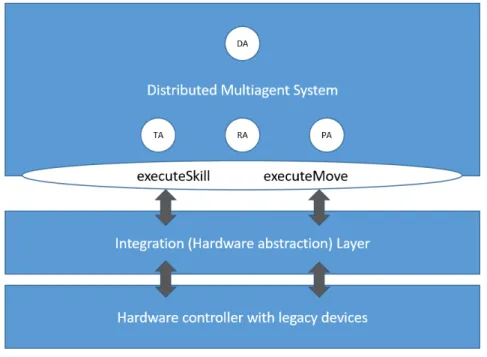
In order to connect the MAS with the edge level, a Integration Layer was created. This Layer has an interface with two main methods, executeSkill and executeMove. These methods are called by the respective agents to be able to perform the requested action in the edge level. The TA will call executeMove to be able to move the product in the factory whereas the RA will call for the executeSkill to be able to make the desired change to the product.
It is in the Integration Layer that the system connects to the edge level and where the flags are managed to run each edge level module. Depending on the agent that calls for the executeSkill and executeMove methods, a different flag is set to true and when read
C H A P T E R 4 . A R C H I T E C T U R E
on the edge level will trigger different modules. This way, the connection between the MAS and the edge level is simplified.
This layered architecture main purpose is to bridge the gap between the emergent production paradigms and legacy hardware. This type of hardware is powerful when per-forming simple tasks, however with these production paradigms, it is no longer possible to keep everything simple. Thus, by creating modules in the edge level, simplifying each task and by managing it through the Integration Layer, it is made possible to use this type of hardware when applied to these new paradigms.
Figure 4.1: Thesis’ architecture.
This chapter will be divided in three sections, the multiagent architecture, the legacy systems architecture and the integration layer architecture.
4.1
MultiAgent Architecture
The multiagent architecture is where the agents are setup and communicate between one another.
In the multiagent environment, there are four different types of Agents. These agents are divided according to their role. There are the TA, PA, RA and the DA.
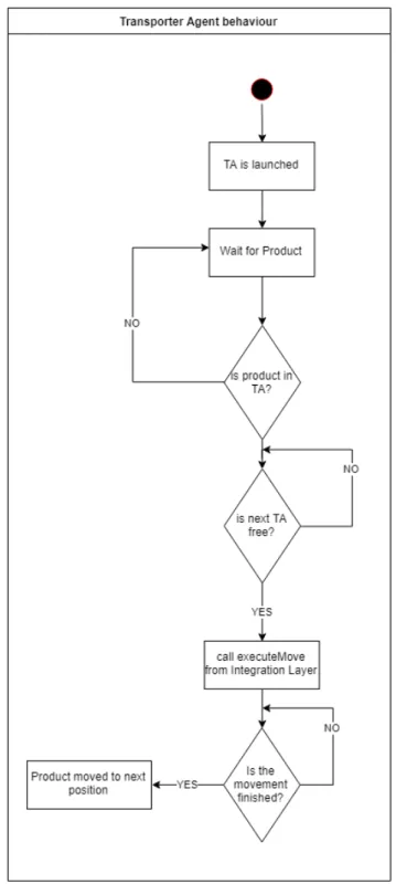
The TA is launched by the DA and the amount of TA’s in the system depends on the factory model. After launch, the TA is on standby waiting for a product. Whenever a product arrives in the TA, the agent will ask the following TA if it is occupied or free. If the Agent is free, it will execute the executeMove method from the Integration Layer, if it is occupied, it will wait for the next TA to be free before moving the product. When the Integration Layer is called, the agent will wait for the layer to tell the TA that the product has arrived in the next position.
4 . 1 . M U LT I AG E N T A R C H I T E C T U R E
Figure 4.2: Transporter Agent’s behaviour.
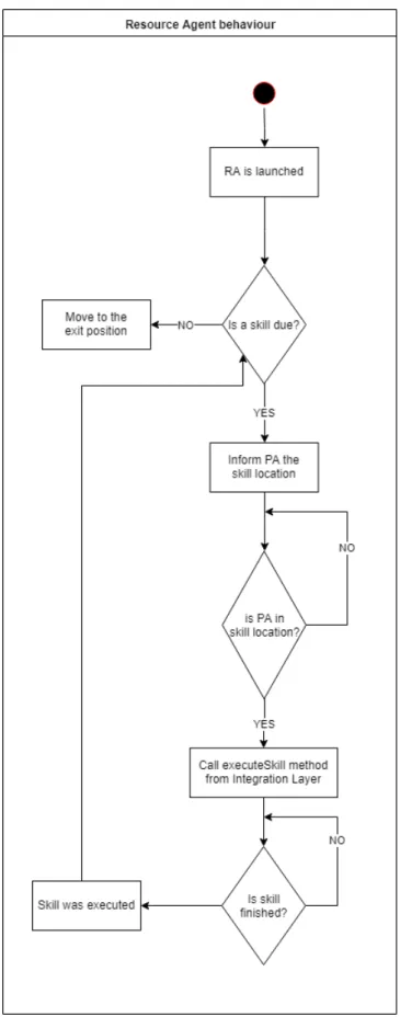
The RA is launched by the DA, the number of RA’s depend on the amount of skills the factory can do. The RA is contacted by the PA to execute a skill, the RA will inform the PA where that skill is. When the product arrives in that skill’s location, the RA will call the method executeSkill that was developed in the Integration Layer. When that happens, the RA will wait for the layer to inform that the skill was done. When it does, if there is no more skills due, the PA will move to the exit, else it will repeat the cycle.
C H A P T E R 4 . A R C H I T E C T U R E
Figure 4.3: Resource Agent’s behaviour.
4 . 1 . M U LT I AG E N T A R C H I T E C T U R E
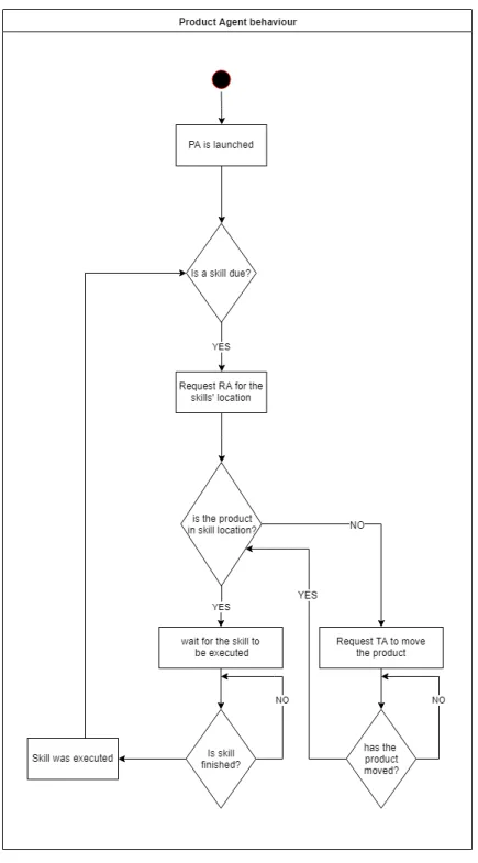
When the PA is launched, it will have skills assigned to itself. Depending on those skills, the product will take its route in the factory. Firstly, the PA will have to know where the skills are, thus contacting the RA. If the product is not in the right position, it will ask the TA to move it to the correct one and then requesting the RA to execute the skill. This cycle repeats itself until there are no more skills.
C H A P T E R 4 . A R C H I T E C T U R E
In the following table there is a summary of the agents and their roles.
Table 4.1: The system’s agents and their role.
Agent Role
Transporter
This agent moves the product from one station to another and it is also responsible for checking if the next station does not have a product in it.
Resource This agent is in charge of selecting the skill that will be executed and informing the TA to where it has to move the product.
Product
This agent is the one that request the skills to be done according to its type. It requests from the resource agent the location of the skill and it requests to the TA to be moved to that position.
Deployment This agent is in charge of launching the agents that are instanced in the data model. It launches the TAs, PAs and RAs.
The agents are in charge of communicating between one another in order to complete the task. Since they are autonomous, they have to figure out what to do after each action. When PA is launched, it has to ask the other agents where the action he wants to perform is, afterwards, the TAs speak among themselves to decide which TA will move PA to the place he requested. The RA is the one that tells the PA where the location of the requested skill is.
4.1.1 Concept of skill
In this system, the agents express their functionalities as skills as defined in [33]. The skills are for an agent like a method for an object. In the architecture there are atomic skills which are directly associated with the manufacturing components’ functionalities. These skills include an interface that have the information needed for their execution. In that information there is:
• Name and ID of the skill.
• The name of the agent that will execute it.
• The description of what is executed.
• The parameters and their data types.
4.1.2 Data model
The agents are launch via DA. This agent has the data on all other agents and their properties and interactions. This data is uploaded from the factory’s data model. In the data model, every skill, resource and transporter are defined. As well as, defining which transporters are next to the transporter being used. The data model has entities which are the Product, Resource, Skill and Transporter and each entity has instances according to the layout of the factory.
![Figure 2.2: The three main characteristics of a CPPS.[8]](https://thumb-eu.123doks.com/thumbv2/123dok_br/15170086.1014626/29.892.222.675.237.490/figure-main-characteristics-cpps.webp)
![Figure 2.3: Reference Architecture Model for Industrie 4.0. [10]](https://thumb-eu.123doks.com/thumbv2/123dok_br/15170086.1014626/30.892.211.681.162.416/figure-reference-architecture-model-industrie.webp)
![Figure 2.5: The four phases of an EPS.[30]](https://thumb-eu.123doks.com/thumbv2/123dok_br/15170086.1014626/36.892.246.646.422.694/figure-the-four-phases-of-an-eps.webp)
![Figure 3.1: Research topics on cloud manufacturing.[36]](https://thumb-eu.123doks.com/thumbv2/123dok_br/15170086.1014626/40.892.163.722.275.648/figure-research-topics-on-cloud-manufacturing.webp)
![Figure 3.2: Fog computing architecture.[38]](https://thumb-eu.123doks.com/thumbv2/123dok_br/15170086.1014626/41.892.223.651.603.893/figure-fog-computing-architecture.webp)