Pedro Miguel Duarte
Cruz
Characterization and Modelling of Software Defined
Radio Front-Ends
Pedro Miguel Duarte
Cruz
Characterization and Modeling of Software Defined
Radio Front-Ends
Tese apresentada à Universidade de Aveiro para cumprimento dos requisitos necessários à obtenção do grau de Doutor em Engenharia Electrotécnica, realizada sob a orientação científica do Professor Doutor Nuno Miguel Gonçalves Borges de Carvalho, Professor Associado com Agregação do Departamento de Electrónica, Telecomunicações e Informática da Universidade de Aveiro.
Apoio financeiro da FCT no âmbito do QREN-POPH na Tipologia 4.1 - Formação Avançada, comparticipado pelo Fundo Social Europeu e por fundos nacionais do MEC.
Dedico este trabalho à Clara, à Rita, aos meus pais Alice e Vítor e ao meu orientador Prof. Nuno Borges Carvalho, pelo incansável apoio e motivação.
“Simple things should be simple, complex things should be possible” “The best way to predict the future is to invent it”
o júri / the jury
presidente / president Prof. Dr. Fernando Manuel dos Santos Ramos Professor Catedrático da Universidade de Aveiro
vogais / examiners committee Prof. Dr. Nuno Miguel Gonçalves Borges de Carvalho Professor Associado com Agregação da Universidade de Aveiro (orientador)
Prof. Dr. José Machado da Silva
Professor Associado da Faculdade de Engenharia da Universidade do Porto
Prof. Dr. José Manuel Neto Vieira Professor Auxiliar da Universidade de Aveiro
Prof. Dr. Roberto Gómez García
agradecimentos / acknowledgements
Gostaria de agradecer ao meu orientador Prof. Nuno Borges Carvalho por todo o apoio, disponibilidade e motivação. Sem a sua ajuda e colaboração todo este trabalho não seria realizável.
Gostaria também de deixar uma palavra especial de agradecimento a todos os amigos e colegas de trabalho por toda a amizade, apoio, disponibilidade e motivação.
Agradeço ainda à Universidade de Aveiro, mais concretamente ao Instituto de Telecomunicações e ao Departamento de Electrónica, Telecomunicações e Informática por me terem proporcionado os meios de trabalho necessários. Da mesma forma agradeço também a todos os colaboradores do Instituto de Telecomunicações pelo maravilhoso ambiente de trabalho e respectivas condições.
Sou também grato à Fundação para a Ciência e a Tecnologia pelo inestimável apoio monetário. O meu agradecimento ainda a todos os participantes da COST action IC0803, em especial ao seu chair, Dr. Apostolos Georgiadis, por me terem proporcionado a possibilidade de apresentar e discutir grande parte dos trabalhos desenvolvidos e também pelo financiamento de uma visita à Tampere University of Technology, na qual aproveito para agradecer a hospitalidade e colaboração do Prof. Mikko Valkama.
Finalmente gostaria de agradecer a todos os meus familiares, com especial destaque à minha esposa Rita, à minha filha Clara, aos meus pais Alice e Vítor pelo maravilhoso e saudável núcleo familiar que me têm proporcionado.
palavras-chave Rádio definido por software, rádio cognitivo, instrumentação multi-domínio, distorção não-linear, multi-portadora, gama dinâmica, largura de banda.
resumo O presente trabalho tem por objectivo estudar a caracterização e modelação
de arquitecturas de rádio frequência para aplicações em rádios definidos por software e rádios cognitivos. O constante aparecimento no mercado de novos padrões e tecnologias para comunicações sem fios têm levantado algumas limitações à implementação de transceptores rádio de banda larga. Para além disso, o uso de sistemas reconfiguráveis e adaptáveis baseados no conceito de rádio definido por software e rádio cognitivo assegurará a evolução para a próxima geração de comunicações sem fios. A ideia base desta tese passa por resolver alguns problemas em aberto e propor avanços relevantes, tirando para isso partido das capacidades providenciadas pelos processadores digitais de sinal de forma a melhorar o desempenho global dos sistemas propostos. Inicialmente, serão abordadas várias estratégias para a implementação e projecto de transceptores rádio, concentrando-se sempre na aplicabilidade específica a sistemas de rádio definido por software e rádio cognitivo. Serão também discutidas soluções actuais de instrumentação capaz de caracterizar um dispositivo que opere simultaneamente nos domínios analógico e digital, bem como, os próximos passos nesta área de caracterização e modelação. Além disso, iremos apresentar novos formatos de modelos comportamentais construídos especificamente para a descrição e caracterização não-linear de receptores de amostragem passa-banda, bem como, para sistemas não-lineares que utilizem sinais multi-portadora.
Será apresentada uma nova arquitectura suportada na avaliação estatística dos sinais rádio que permite aumentar a gama dinâmica do receptor em situações de multi-portadora. Da mesma forma, será apresentada uma técnica de maximização da largura de banda de recepção baseada na utilização do receptor de amostragem passa-banda no formato complexo.
Finalmente, importa referir que todas as arquitecturas propostas serão acompanhadas por uma introdução teórica e simulações, sempre que possível, sendo após isto validadas experimentalmente por protótipos laboratoriais.
keywords Software defined radio, cognitive radio, mixed-domain instrumentation, nonlinear distortion, multi-carrier, dynamic range, bandwidth maximization.
abstract This work investigates the characterization and modeling of radio frequency
front-ends for software defined radio and cognitive radio applications. The emergence of new standards and technologies in the wireless communications market are raising several issues to the implementation of wideband transceiver systems. Also, reconfigurable and adaptable systems based on software defined and cognitive radio models are paving the way for the next generation of wireless systems. In this doctoral thesis the fundamental idea is to address the particular open issues and propose appropriate advancements by exploring and taking profit from new capabilities of digital signal processors in a way to improve the overall performance of the novel schemes.
Receiver and transmitter strategies for radio communications are summarized by concentrating on the usability for software defined radio and cognitive radio systems. Available instrumentation and next steps for analog and digital radio frequency hardware characterization is also discussed.
Wideband behavioral model formats are proposed for nonlinear description and characterization of bandpass sampling receivers, as well as, for multi-carrier nonlinear systems operation. The proposed models share a great flexibility and have the freedom to be simply expanded to other fields.
A new design for receiver dynamic range improvement in multi-carrier scenarios is proposed, which is supported on the useful wireless signals statistical evaluation. Additionally, receiver-side bandwidth maximization based on higher-order bandpass sampling approaches is evaluated.
All the proposed designs and modeling strategies are accompanied by theoretical backgrounds and simulations whenever possible, being then experimentally validated by laboratory prototypes.
i
Table of Contents
Table of Contents i
List of Figures iii
List of Tables v
List of Acronyms vii
Chapter 1 – Introduction 1
1.1 Motivation and Outline ... 3
1.2 Main Contributions ... 4
Chapter 2 – Designing and Testing Multiband Radio Architectures 7 2.1 Architectures for SDR/CR Receivers ... 7
2.2 Architectures for SDR/CR Transmitters ... 12
2.3 SDR/CR Measurement Instrumentation ... 18
2.4 Concluding Remarks ... 21
Chapter 3 – Wideband Nonlinear Behavioral Modeling 23 3.1 Behavioral Modeling of Bandpass Sampling Receivers ... 23
3.1.1 Proposed Nonlinear Behavioral Model ... 25
3.1.3 Parameter Extraction Procedure ... 28
3.1.4 Model Validation with QPSK Signal ... 31
3.1.4.1 Frequency Domain Results ... 32
3.1.4.2 Symbol Evaluation Results ... 33
3.2 Behavioral Modeling of Multi-Carrier Devices ... 34
3.2.1 Review of Multi-Carrier Nonlinear Effects ... 34
3.2.2 Proposed Multi-Carrier Nonlinear Model ... 37
3.2.3 Measurements Validation ... 39
3.3 Concluding Remarks ... 41
Chapter 4 – Dynamic Range and Bandwidth Constraints 43 4.1 Dynamic Range in Wideband Receivers ... 43
4.1.1 Techniques for Dynamic Range Improvement ... 46
ii
4.1.1.2 Non-Uniform Quantization by Companding ... 47
4.1.1.3 Averaging Multiple Analog-to-Digital Converters ... 49
4.1.1.4 Other Feasible Techniques ... 50
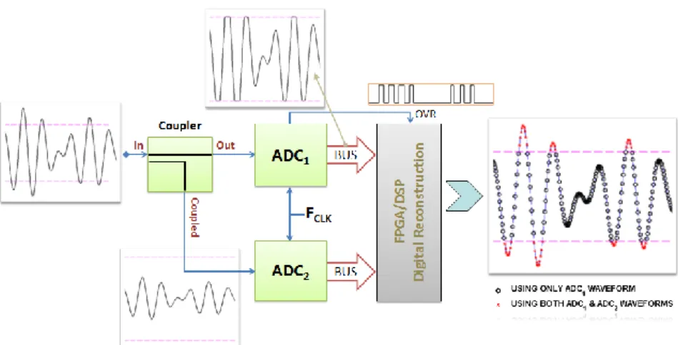
4.1.2 Proposed Architecture for Dynamic Range Enhancement ... 50
4.1.3 Measurement Results ... 54
4.2 Bandwidth Maximization by Second-Order Sampling ... 57
4.2.1 Proposed Design with Digital Compensation ... 59
4.2.2 Measurement Results ... 61
4.3 Concluding Remarks ... 63
Chapter 5 – Conclusions and Outlook 65 References 67 Appendix A – Annexed Papers 75 [J1] – Designing and Testing Software Defined Radios ... 77
[J2] – Wideband Behavioral Model for Nonlinear Operation of Bandpass Sampling Receivers ... 91
[J3] – Improving Dynamic Range of SDR Receivers for Multi-Carrier Wireless Systems ... 103
[C1] – PWM Bandwidth and Wireless System Peak-to-Minimum Power Ratio .... 117
[C2] – Modeling Band-Pass Sampling Receivers Nonlinear Behavior in Different Nyquist Zones ... 123
[C3] – Multi-Carrier Wideband Nonlinear Behavioral Modeling for Cognitive Radio Receivers ... 129
[C4] – Enhanced Architecture to Increase the Dynamic Range of SDR Receivers 135 [C5] – Evaluation of Second-Order Bandpass Sampling Receivers for Software Defined Radio ... 141
iii
List of Figures
Fig. 1.1 – Typical implementation for an ideal software-defined radio, [2]. ... 1
Fig. 2.1 – A super-heterodyne receiver architecture. ... 8
Fig. 2.2 – A zero-IF receiver architecture. ... 9
Fig. 2.3 – A bandpass sampling receiver architecture. ... 11
Fig. 2.4 – A super-heterodyne transmitter architecture. ... 13
Fig. 2.5 – A direct-conversion transmitter architecture. ... 13
Fig. 2.6 – Block diagram of a Kahn amplifier section. ... 15
Fig. 2.7 – Simplified circuit of a class-S power amplifier. ... 15
Fig. 2.8 – Block diagram of a “polar” transmitter. ... 17
Fig. 2.9 – Mixed-domain instrumentation for SDR characterization. ... 19
Fig. 2.10 – Combination of several instruments employed in a SDR transmitter. ... 20
Fig. 3.1 – Process of folding that occurs in the sample-and-hold circuit showing the folding and overlapping of signals in the first NZ. ... 24
Fig. 3.2 – Diagram of the low-pass equivalent conversion of each cluster. ... 26
Fig. 3.3 – Proposed design for the BPSR behavioral model. ... 26
Fig. 3.4 – The experimental test bench proposed in [13]. ... 29
Fig. 3.5 – Flowchart diagram of the kernels extraction procedure. ... 31
Fig. 3.6 – Entire bandwidth (smoothed) of measured and modeled outputs for a QPSK signal centered at 11.5 MHz (left) and 69 MHz (right). ... 32
Fig. 3.7 – Spectrum of measured and modeled results, at carrier band and 2nd harmonic band for a QPSK signal centered at 11.5 MHz (left) and 69 MHz (right). ... 33
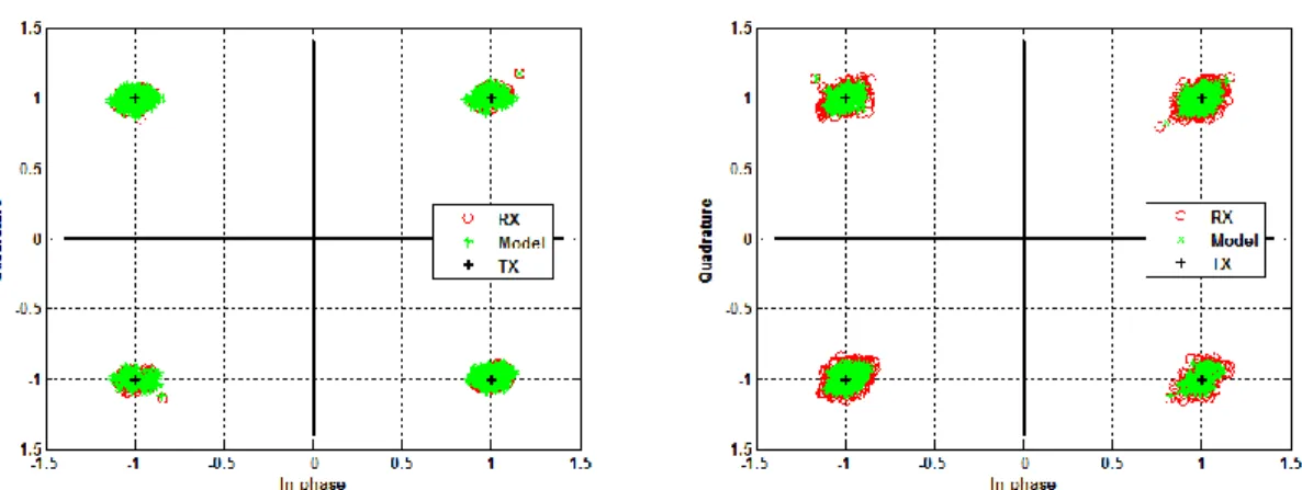
Fig. 3.8 – Normalized constellation diagrams for the QPSK signal centered at 11.5 MHz (left) and 69 MHz (right). ... 34
Fig. 3.9 – Obtained spectrum from the nonlinear model of expression (3.11) when excited by a multi-carrier signal. ... 36
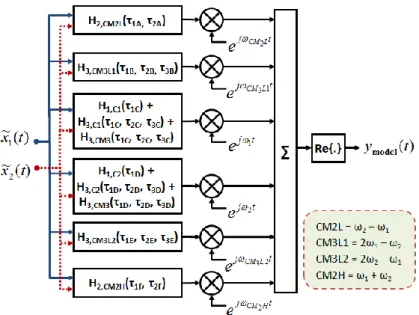
Fig. 3.10 – Proposed design for the multi-carrier nonlinear behavioral model. ... 38
Fig. 3.11 – The experimental test bench used. ... 38
Fig. 3.12 – Measured and simulated results of the spectrum at carrier one (left) and spectrum at carrier two (right). ... 39
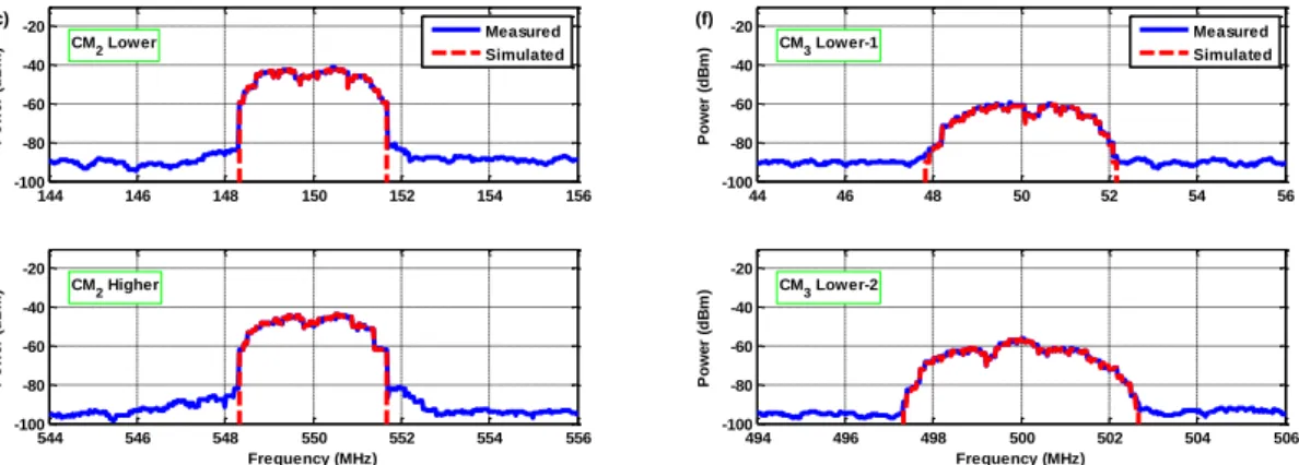
Fig. 3.13 – Measured and simulated results of the spectrum at 2nd-order cross-modulations (left) and spectrum at 3rd-order cross-modulations (right). ... 40
iv
Fig. 3.14 – Measured and simulated results for the time envelope of carrier one (left) and time envelope of carrier two (right). ... 40 Fig. 4.1 – Illustration of limited instantaneous dynamic range and its potential improvements. ... 45 Fig. 4.2 – Explanation of the VGA plus ADC limitation when in a multi-carrier wideband scenario. ... 46 Fig. 4.3 – Block diagram implementation of the companding function. ... 48 Fig. 4.4 – Proposed architecture to enhance the receiver instantaneous dynamic range with representative waveforms in relevant branches. ... 51 Fig. 4.5 – General flowchart diagram of the digital reconstruction procedure. ... 52 Fig. 4.6 – Different types of quantization (4-bit case) schemes produced by the different architectures: (a) VGA plus ADC, (b) companding, and (c) proposed. ... 53 Fig. 4.7 – Probability density functions of different signals. ... 53 Fig. 4.8 – Laboratory setup used in the measurement validation example. ... 54 Fig. 4.9 – Multi-carrier signal composed by a high-power interferer and a low-power QPSK signal, before (solid line) and after BPSR procedure (dashed line). ... 55 Fig. 4.10 – Measured EVM for a low-power QPSK signal received simultaneously with a high-power interferer for the VGA plus ADC and proposed cases. ... 56 Fig. 4.11 – Constellation diagrams of the low-power QPSK signal for the VGA plus ADC and proposed architectures, when received at (a) -30dBc and (b) -35dBc to the interferer. ... 56 Fig. 4.12 – General block diagram of a second-order BPSR. ... 57 Fig. 4.13 – Block diagram of the proposed design for complex BPSR. ... 59 Fig. 4.14 – Performance of a commercial 90º hybrid within the band of interest measured in a commercial vector network analyzer. ... 59 Fig. 4.15 – Frequency domain illustration of the working process for the proposed design. ... 60 Fig. 4.16 – Frequency domain results for two sinusoidal signals (left) and a QPSK signal interfered by a multisine signal (right). ... 62 Fig. 4.17 – Frequency domain results for multiband reception (left) and signal demodulation of a QPSK signal under multisine interference for single path and proposed design (right). ... 62 Fig. 4.18 – Signal demodulation results illustrating the QPSK and 16-QAM baseband I/Q information for a multiband reception system. ... 62
v
List of Tables
Table 3.A – Measured and modeled integrated powers for the QPSK excitation. ... 33 Table 3.B – Measured and modeled EVM values for the QPSK excitation. ... 34 Table 3.C – Obtained mixtures from the model in (3.11) for two excitation signals. .... 36 Table 3.D – Measured and simulated output powers for each nonlinear cluster. ... 40 Table 4.A – Measured EVM results for a QPSK signal with a multisine interferer. ... 63 Table 4.B – Measured EVM results for multiband modulated signal reception using the proposed design. ... 63
vi
vii
List of Acronyms
ADC Analog-to-Digital Converter AGC Automatic Gain Control AWG Arbitrary Waveform Generator
BPSK Binary Phase Shift Keying
BPSR Bandpass Sampling Receiver
CR Cognitive Radio
DAC Digital-to-Analog Converter DSP Digital Signal Processing
EER Envelope Elimination and Restoration FFT Fast Fourier Transform
FPGA Field-Programmable Gate Array
GSM Global System for Mobile Communications
I/Q In-phase/Quadrature
IF Intermediate Frequency
IFFT Inverse Fast Fourier Transform
LINC Linear Amplification with Nonlinear Components
LO Local Oscillator
LNA Low Noise Amplifier
LTE Long Term Evolution
NMSE Normalized Mean Square Error
NZ Nyquist Zone
OFDM Orthogonal Frequency Division Multiplex
PA Power Amplifier
PAPR Peak-to-Average Power Ratio
PDF Probability Density Function PWM Pulse-Width Modulation
QAM Quadrature Amplitude Modulated QPSK Quadrature Phase Shift Keying
RF Radio Frequency
viii
SNDR Signal-to-Noise and Distortion Ratio SNR Signal-to-Noise Ratio
SPI Six-Port Interferometer VGA Variable Gain Amplifier
Chapter 1 – Introduction
Radio communications are seeing significant changes and improvements every day, with several ideas being delineated for radio architectures approaching multiband and multi-carrier designs, as for instance, novel and demanding concepts being planned for long term evolution (LTE) and LTE-advanced standards with carrier aggregation [1].
Recent developments on software defined radio (SDR) technology are paving the way for next generation of wideband communications and will certainly drive the implementation of a universal radio.
Moreover, SDR as proposed by Mitola [2] is now being accepted as the most probable solution for resolving the need of integration between actual and future wireless communication standards. SDRs take advantage of the processing power of modern digital processor technology to replicate the behavior of a radio circuit. Such a solution allows inexpensive, efficient interoperability between the available standards and frequency bands, because these devices can be improved, updated and change its operation by a simple change in software algorithms.
The ultimate goal for a SDR architecture is to push the digitization closest to the antenna as much as possible and thus, providing an increased adaptation and reconfigurability in the digital domain by the use of current digital signal processors (DSP, FPGA, etc.) capable to correctly treat the incoming signals. A common implementation for the SDR concept is shown in Fig. 1.1.
This SDR concept is also the basis for cognitive radio (CR) approaches [3], in which the underneath concept imposes strong changes in terms of both complexity and flexibility of operation due to its potential adaptation to the air interface. A promising application for this CR technology is to implement a clever management of spectrum occupancy by use opportunistic radios, in which the radio will adapt and employ spectrum strategies in order to take profit from portions of spectra that are not being used by other radio systems at a given moment.
Furthermore, latest wireless communications standards have been increasingly adopting orthogonal frequency-division multiplexing (OFDM) scheme because of OFDM’s spectral efficiency and capability to transmit high data rates over broadband radio channels subjected to multipath fading and shadowing issues. The scenario of conjugation between both multiband systems and OFDM-based schemes will lead to high peak waveforms, commonly characterized by its peak-to-average power ratio (PAPR), and thus limits the amount of power that can be received or transmitted without distortion, [4] [5].
In this sense, the expected developments will impose huge impairments in the design of radio receivers and associated characterization techniques. In fact, a major bottleneck for the deployment of SDR/CR systems is the enabling hardware to realize such spectrum agile radio transceivers.
For example, high dynamic range is a very important figure of merit when dealing with multi-carrier multiband digital receivers, [6], since the receiving unit should cope with signals having very different power levels at same time. Associated to this concern is the PAPR problem that immediately degrades the quality of the transmitted and received signal, either by requiring high values of input power back off in power amplifiers, and thus reduce its efficiency, or by the fact that it imposes a degradation of the signal-to-noise and distortion ratio (SNDR) in receiver analog-to-digital converters (ADCs) [7]. This still remains a problem to be fully resolved and not much worth literature is available on the subject, mainly when concentrating on multiband multi-carrier wireless systems.
Wideband multi-carrier receiver design is also another important theme to evaluate. Some techniques have been presented as hybrid filter banks [8] and also second-order bandpass sampling receivers (BPSR), [9] and [10], but the presented ideas are mainly focused on the mathematical forms of this signal processing theory and not necessarily based on true hardware implementations.
In this context another matter that still lacks a solution is on how to model multiband multi-carrier nonlinear transceivers. Despite several papers has been published on nonlinear models, few are dedicated to multi-carrier systems and normally only studied the transmitter path, [11] [12].
A transversal subject is the test and measurement of such SDR/CR systems, which will demand for specifically designed mixed-signal instrumentation capable to operate in the two domains [13]. Several solutions suitable for SDR/CR characterization are available in the instrumentation market, such as mixed-signal oscilloscopes that are capable of operating in the analog and digital domains at same time, allowing time synchronization between those waveforms. Other approach combines several instruments, including logic analyzers, oscilloscopes, vector signal analyzers, or real-time signal analyzers, [14] and [15]. Nevertheless, those solutions demonstrate some limitations and are yet not able to characterize a complete SDR/CR front-end. This subject will be introduced in more detail in chapter 2.3 (below), but recent advances in this area achieved by the student’s research group have not been considered for the present doctoral thesis.
1.1
Motivation and Outline
The motivation for this thesis was exactly to address some of the open issues listed in the previous section, having in mind the determination to expand the scientific state-of-the-art within SDR and CR areas.
In this sense, important goals have been accomplished during this doctoral study as follows:
Wideband behavioral model for bandpass sampling receivers nonlinear operation Nonlinear behavioral model for multi-carrier devices covering inter-modulation
and cross-modulation distortion mechanisms
Architecture to enhance the receiver dynamic range when in presence of multiband multi-carrier wireless signals
Design for receiver bandwidth maximization based on second-order bandpass sampling receivers
The basic operation principle behind the majority of proposed concepts was to pass, as much as possible, to the digital domain any type of processing on the incoming signals, in order to take profit from the increased capabilities of digital signal processors. Regarding the modeling theme the idea was mainly to create behavioral strategies to improve the understanding of real-world nonlinear processes.
It is worth mention that experimental work was carried out with the purpose of validating all concepts. Theoretical modeling and simulations were also performed whenever possible or useful.
The introductory part of the thesis provides a brief background about the SDR and CR areas, to which all the work performed for this thesis belongs. In chapter 2 is presented a high-level overview of solutions for receiver and transmitter architectures for SDR and CR front-end design and measurement instrumentation needed for these new paradigms. Chapter 3 deals with behavioral model strategies based on Volterra series theory for representation of specific bandpass sampling receiver operation, but also to describe general multi-carrier nonlinear situations. Receiver’s dynamic range and bandwidth limitations are discussed in chapter 4. In this chapter are proposed techniques for receiving dynamic range increase and bandwidth maximization. The last chapter presents the final conclusion and an outlook on future projects originated from the work done for this thesis.
As detailed in the following section, all the concepts discussed in this thesis were either published or submitted to prestigious scientific journals of the present research areas [J1]– [J3], presented in relevant international conferences [C1]–[C5], and other additional works published in the most appropriate places [A]–[K] not used as basis of the thesis.
1.2
Main Contributions
On the purpose of this thesis writing the contents of most relevant publications, inside each particular topic, have been considered. In this line, the document is largely supported on the following papers:
[J1] P.M. Cruz, N.B. Carvalho and K.A. Remley, “Designing and Testing Software-Defined Radios”, IEEE Microwave Magazine, vol. 11, no. 4, June 2010.
[J2] P.M. Cruz and N.B. Carvalho, “Wideband Behavioral Model for Nonlinear Operation of Bandpass Sampling Receivers”, IEEE Transactions on
Microwave Theory and Techniques, vol. 59, no. 4, April 2011.
[J3] P.M. Cruz, N.B. Carvalho and K.A. Remley, “Improving Dynamic Range of SDR Receivers for Multi-Carrier Wireless Systems”, Submitted to IEEE
Transactions on Circuits and Systems Part I: Regular Papers.
[C1] P.M. Cruz and N.B. Carvalho, “PWM Bandwidth and Wireless System Peak-to-Minimum Power Ratio”, European Microwave Integrated Circuits
Conference, Rome, Italy, September 2009.
[C2] P.M. Cruz and N.B. Carvalho, “Modeling Band-Pass Sampling Receivers Nonlinear Behavior in Different Nyquist Zones”, IEEE MTT-S International
Microwave Symposium, Anaheim, CA, May 2010.
[C3] P.M. Cruz and N.B. Carvalho, “Multi-Carrier Wideband Nonlinear Behavioral Modeling for Cognitive Radio Receivers”, European Microwave
Integrated Circuits Conference, Manchester, United Kingdom, October 2011.
[C4] P.M. Cruz and N.B. Carvalho, “Enhanced Architecture to Increase the Dynamic Range of SDR Receivers”, IEEE Radio and Wireless Symposium, Phoenix, AZ, January 2011.
[C5] P.M. Cruz, N.B. Carvalho and M.E. Valkama, “Evaluation of Second-Order Bandpass Sampling Receivers for Software Defined Radio”, European
Microwave Integrated Circuits Conference, Amsterdam, Netherlands,
October 2012.
Additionally, several other contributions have been accomplished but are not included in the thesis. Their content partially overlaps with the annexed papers or are out of the scope of this thesis. The following list of publications is enumerated by the date of appearance.
[A] P.M. Cruz and N.B. Carvalho, “Multi-Mode Receiver for Software Defined Radio”, 2nd
Congress of the Portuguese Committee of URSI, Lisboa, Portugal,
November 2008.
[B] P.M. Cruz and N.B. Carvalho, “PAPR Evaluation in Multi-Mode SDR Transceivers”, European Microwave Conference, Amsterdam, Netherlands, October 2008.
[C] P.M. Cruz and N.B. Carvalho, “Characterization of a SDR Front-End Receiver with Multisine Excitations”, 7th
Conference on Telecommunications – ConfTele 2009, Santa Maria da Feira, Portugal, May 2009.
[D] P.M. Cruz and N.B. Carvalho, “Architecture for Dynamic Range Extension of Analog-to-Digital Conversion”, IEEE International Microwave Workshop
Series on RF Front-ends for Software Defined and Cognitive Radio Solutions,
Aveiro, Portugal, February 2010.
[E] P.M. Cruz, H.C. Gomes and N.B. Carvalho, “Receiver Front-End Architectures - Analysis and Evaluation” – Chapter in Advanced Microwave
and Millimeter Wave Technologies Semiconductor Devices Circuits and Systems, Edited by Moumita Mukherjee, In-Tech, Austria, March 2010.
[F] P.M. Cruz, D.C. Ribeiro and N.B. Carvalho, “Virtualized Instrumentation for Emergent Radio Technologies”, 5th
Congress of Portuguese Committee of URSI, Lisboa, Portugal, November 2011.
[G] D.C. Ribeiro, P.M. Cruz and N.B. Carvalho, “Two-Tone Measurement Technique to apply on Mixed-Domain Instrumentation”, 5th Congress of Portuguese Committee of URSI, Lisboa, Portugal, November 2011.
[H] P.M. Cruz, N.B. Carvalho and M.E. Valkama, “On the Implementation of a Mixed Frequency-Time Simulator for Band-Pass Sampling Receivers”,
Conference on Electronics, Telecommunications and Computers, Lisboa,
Portugal, November 2011.
[I] D.C. Ribeiro, P.M. Cruz and N.B. Carvalho, “Corrected Mixed-Domain Measurements for Software Defined Radios”, European Microwave
Conference, Amsterdam, Netherlands, October 2012.
[J] P.M. Cruz and N.B. Carvalho, “Characterization of Software Defined and Cognitive Radio Front-Ends for Multi-mode Operation” – Chapter in
Microwave and Millimeter Wave Circuits and Systems: Emerging Design, Technologies and Applications, Edited by A. Georgiadis, H. Rogier, L.
Roselli, P. Arcioni, Wiley, November 2012.
[K] P.M. Cruz, D.C. Ribeiro, N.B. Carvalho and M.E. Valkama, “Measurement-based Modelling of Analogue-to-Digital Converters under RF Impairments”, Submitted to IET Circuits, Devices & Systems.
Chapter 2 – Designing and Testing Multiband Radio
Architectures
This chapter will start first by presenting the most used receiver strategies for radio communications and concentrate on the usability for SDR/CR systems.
Afterwards, several architectures for transmitter front-ends are described including traditional heterodyne and zero-IF, but also emergent configurations as digitally-aided “polar” and Doherty designs that account for with some improvements in the efficiency of the vital amplifier block.
Finally, the available instrumentation in the market for analog and digital SDR/CR characterization is summarized. Also, a completely synchronous mixed analog-digital instrumentation proposed in [13] is discussed.
The chapter is mainly supported in the annexed paper [J1] for contributions on architectures for receivers and transmitters of SDR front-ends, and required instrumentation for a correct analog and digital characterization. It is also considered the study made in paper [C1], which shows a relationship between sampling frequency and PAPR of input waveforms. The previous work also demonstrated that coding efficiency of input waveforms will become a key figure of merit for switched power amplifier (PA) transmitter efficiency.
2.1
Architectures for SDR/CR Receivers
For SDR/CR applications several receiver architectures may be used, ranging from common super-heterodyne, zero-IF, and low-IF designs to band-pass sampling approaches, but also recent proposals of six-port interferometers and direct RF sampling with analog decimation. All these are valid and practical receiving architectures, but some are gaining visibility over the others mainly because of the actual advancements in ADC and digital-to-analog converter (DAC) technology and the enormous increase in the capabilities of digital signal processors.
The basic review that is done here is mostly based on [16] and [17]. Starting with the well-known super-heterodyne receiver (Fig. 2.1), where the received signal at the antenna is translated to an intermediate frequency (IF) using a down conversion mixer, band-pass filtered and amplified. This is followed by a second stage for down conversion to baseband based on in-phase/quadrature (I/Q) demodulation and then converted to the digital domain to be treated. This architecture is now adopted mostly for higher radio frequency (RF) and millimeter-wave frequency designs, [18] and [19], such as point-to-point wireless links. In these applications, the solutions discussed below are not practical. Actually, super-heterodyne receivers have a number of substantial problems when they are applied to SDR applications. Generally, a number of fabrication technologies are used, making full on-chip integration difficult. As well, they are usually designed to a specific channel (in a particular wireless standard). This prevents the expansion of the receiving band for use with signals having various modulation formats and occupied bandwidths. Therefore, the super-heterodyne configuration is not attractive for use in SDR receivers due to its complicated expansion for multiband reception.
Fig. 2.1 – A super-heterodyne receiver architecture.
Another approach is the zero-IF receiver, [20] and [21], shown in Fig. 2.2, which is a simplified version of the super-heterodyne architecture. The whole received RF band is selected by a band-pass filter and amplified by a low-noise amplifier (LNA), as in the previous architecture. It is then directly down converted to DC by a mixer and converted to the digital domain using an ADC. Compared to the heterodyne architecture, this has a clear reduction in the number of analog components and also allows the use of a filter having
much less stringent specifications than the image-reject filter. As a result, this architecture can make use of a high level of integration, making it a common architecture for multiband receivers such as the one described in [22] and for complete transceiver architectures as in [22] and [23]. However, some of these components can be much more difficult to design due to the required performance of each. Also, the direct translation to DC can generate some issues such as a DC offset [24]. Other issues are related to second-order intermodulation products that are generated around DC, and, since the mixer output is a baseband signal, it can be easily corrupted by the large flicker noise of the mixer [25]. Its advantages and the possibility to minimize the cited disadvantages make this the most commonly used configuration in radio receivers currently.
Fig. 2.2 – A zero-IF receiver architecture.
A similar configuration to the zero-IF architecture is the low-IF receiver [26], in which the RF signal is mixed down to a nonzero low or moderate IF instead of going directly to DC. In this case, a RF band-pass filter is applied to the incoming signal which is then amplified. The signal is converted to the digital domain with an ADC of relatively robust performance, which allows the use of digital signal processing for digital filtering for channel-selection, mitigate I/Q imbalances in quadrature demodulators, etc. This architecture still allows a high level of integration and, in addition, does not suffer from the problems of the zero-IF architecture because the desired signal is not situated around DC. However, in this architecture, the image frequency problem is reintroduced and the ADC power consumption is increased because now a higher conversion rate is required.
Finally, an alternative to the previous solutions is the band-pass sampling receiver [27] and [28], shown in Fig. 2.3. In this architecture, the received signal is filtered by an RF band-pass filter that can be a tunable filter or a bank of filters. It is amplified using a wideband LNA. The signal is sampled and converted to the digital domain by a high sampling rate ADC and digitally processed. This configuration is based on the fact that all energy from DC to the input analog bandwidth of the sample and hold circuit of the ADC will be folded back to the first Nyquist zone (NZ), [0, fS/2], without any mixing down
conversion needed. This architecture takes advantage of some properties of sample and hold circuit. As was described in [28], it is possible to pinpoint the resulting intermediate frequency, fIF, based on the relationship:
) , ( , ) , ( , 2 IF S C S S C IF S C f f rem f f odd f f rem f even is f f fix if (2.1)
where fC is the carrier frequency, fS is the sampling frequency, fix(a) is the truncated
portion of argument a, and rem(a,b) is the remainder after division of a by b.
In this case, the RF band-pass signal filtering plays an important role because it must reduce all signal energy (essentially noise) outside the NZ of the desired frequency band that otherwise would be aliased. If not filtered, the signal energy (noise) outside the desired NZ is folded back to the first zone together with the desired signal, producing a degradation of the signal-to-noise ratio (SNR). This may be given by:
0 10 * 1 log * 10 N n N S SNR i (2)where S represents the desired-signal power, Ni and N0 are in-band and out-of-band noise,
respectively, and n is the number of aliased NZs.
The advantage of this configuration is the sampling frequency needed and the subsequent processing rate are proportional to the information bandwidth, rather than to the carrier frequency. This reduces the number of components.
However, some critical requirements exist. For example, the analog input bandwidth of the sample and hold circuit inside the ADC must include the RF carrier, which is a serious problem, considering the sampling rate of modern ADCs. Clock jitter can also be a vital problem. As well, RF band-pass filtering is required to avoid overlap of signals.
Fig. 2.3 – A bandpass sampling receiver architecture.
Other architectures being proposed for use in SDR receivers involve use of direct RF sampling techniques based on discrete-time analog signal processing to receive the signal, such as the ones developed in [29] and [30]. These methods are still in a very immature stage but should be further studied due to their potential efficiency in implementing reconfigurable receivers.
Furthermore, a quite old technique known as six-port interferometer (SPI) is now being proposed to become an outstanding architecture for SDR receivers and transmitters [31]. This technique was mainly utilized for instrumentation and measurement applications as in [32], [33] and [34]. Nevertheless, quite recent works demonstrate the use of a SPI radio receiver with some required modifications to operate at millimeter-wave frequencies for quadrature-phase-shift-keying (QPSK) and binary-phase-shift-keying (BPSK) modulated signals [35]. An SPI demodulator eliminates the use of down-converting mixers and obtains directly the base-band data with a decoder (by means of new phase spectrum demodulation schemes) from the four interferometer output signals.
On the other hand, the support of quadrature-amplitude-modulated (QAM) signals by the SPI radio needs for more research and some developments are ongoing to include it.
The possible operation of a SPI radio at very high transmission rates (large bandwidths) by using mostly passive devices and its low-cost implementation can be confirmation factors for these SPI radio techniques.
2.2
Architectures for SDR/CR Transmitters
In this section, we discuss several transmitter architectures that have potential application to SDR systems. As we know, a transmitter is not only the PA but a variety of other circuit components collectively known as the front-end. The design of the PA is one of the most challenging aspects of transmitter design, having a high impact on the coverage, the product cost and the power consumption of a wireless system. Here we begin with a consideration of the complete transmitter architecture and in the following it is discussed the PA as it relates to SDR. This review is mainly based on [36].
The first architecture, Fig. 2.4, is the common super-heterodyne transmitter, which is the dual of the super-heterodyne receiver presented in Fig. 2.1. The signal is created in the digital domain and then converted to analog domain using simple DACs. The signal is modulated at an intermediate frequency, where it is amplified and filtered to eliminate harmonics that were generated during modulation. Finally, the signal is up-converted to RF using a local oscillator (LO2), filtered to remove unwanted image sidebands, amplified by a
RF power amplifier and applied to the transmit antenna. As well, the I/Q modulator works at IF, which means hardware components are easier to design than they would be for an RF-based modulator. Finally, the overall gain can be controlled at IF where it is easier to build high-quality variable gain amplifiers. However, such architecture has a significant number of problems, as in the receiver’s case. Due to that, this architecture is mostly adopted for microwave point-to-point wireless links as, for example, in backhaul communications [18], [19] and of course in the already mentioned field of radio transmitters. The amount of circuitry and low integration level, as well as the required linearity of the PA and the difficulty to implement multi-mode operation generally prevent the use of super-heterodyne transmitters in SDR applications.
Fig. 2.4 – A super-heterodyne transmitter architecture.
Fig. 2.5 shows a block diagram of a direct-conversion transmitter, [37] and [38], that is a simplified version of the super-heterodyne front-end. As in the last case, two DACs are used to convert the baseband digital I and Q signals to the analog domain. The low-pass filters that follow eliminate Nyquist images and improve the noise floor. These signals are directly modulated to RF by the use of a high-performance I/Q modulator. After that, the signal is filtered by a band-pass filter centered at the desired output frequency and is amplified by a PA.
Fig. 2.5 – A direct-conversion transmitter architecture.
In a frequency-agile system, the signal chain must be designed so that carrier frequencies can be synthesized over a defined range that will require a broadband post-modulator or a tunable post-post-modulator filtering to attenuate out-of-band noise. Thus, due to a phenomenon known as injection pulling, [39], the strong signal at the output of the PA
may couple to the LO. As a result, the frequency of the LO can be pulled away from the desired value.
Even though this architecture reduces the amount of circuitry required and easily allows high-level integration, it carries some disadvantages such as possible carrier leakage, phase-gain mismatch. As well, gain control may need to be carried out at RF and, this architecture also requires a PA with good linearity. With careful design, these transmitters can be employed in SDR applications, and, with the development of integrated technologies, we have witnessed a fast migration from the super-heterodyne architecture to direct-conversion transmitters.
In the previous architectures, the RF PA blocks used are class-A, AB or B, which demonstrate the highest efficiency when operated in the compression region, or are class-D, E and F operated in switching mode [40]. The latter highly efficient PAs operate in a strongly nonlinear mode. As a result, they can only amplify constant-envelope modulated signals such as those used in the GSM access format. Modulation types such as QAM that are used in new access formats, such as wideband code-division multiple access (W-CDMA) and OFDM have inherently high PAPRs. The standard way to avoid compression of PAs is to operate them in “back-off” mode, that is, to reduce the input power until the PA is not driven into compression. Unfortunately, this lowers efficiency significantly, especially for high PAPR signals. Several linearization techniques, for example, feedback, feed-forward or digital pre-distortion, [40] and [41], have been proposed and evaluated, but these are not yet widely used in fully integrated power amplifiers.
The problem of transmitting a high PAPR signal efficiently has been thoroughly investigated over the years. To increase efficiency, a technique proposed some years ago, the Kahn technique, [42], is now being studied for use in new transmitter architectures.
Envelope elimination and restoration (EER), proposed by Kahn, is one method to linearize highly nonlinear, highly efficient transmitters. In these systems, the supply voltage of the output RF power amplifier is dynamically adjusted to restore the amplitude onto a phase-modulated representation of the signal. Fig. 2.6 shows the traditional EER architecture.
Fig. 2.6 – Block diagram of a Kahn amplifier section.
Although it is a very appealing concept, the actual implementation is very challenging. The challenge arises mainly from the design of a perfect delay line, an accurate limiting stage, an improved bias circuitry that could allow high PAPR and high bandwidths, and also from the required bandwidth that the switched/saturated RF PA should cover to amplify the phase-modulated signal [43].
For this reason, in modern realizations, with the enormous improvements in digital signal processing capabilities, it has been advantageous to implement the envelope detector, the limiter and the delay line (time delay) digitally. Such a digital version of an EER transmitter is used in the “polar” transmitter, which will be explained later.
A visionary solution uses pulse-width modulation (PWM) to create the so-called all-digital transmitter that will be described next. This all-all-digital approach is important because of the implementation of novel SDR configurations that will enable cognitive approaches. This approach also enables a green environment because it allows the use of very-high-efficiency transmitters, such as the class-S PA shown in Fig. 2.7.
Furthermore, as the speed of digital signal processors advances, algorithms in which an FPGA provides signals at RF can be envisioned (particularly for switching amplifiers in which the inputs are digital PWM signals and the outputs are RF modulated signals) in order to develop the so called “all-digital transmitter”.
As shown in Fig. 2.7, the class-S amplifier [44] can be a pure switching amplifier followed by a low-pass filter (to create an envelope signal) or a band-pass filter (to create an RF signal). This amplifier ideally will consume no DC power because the output voltage and the current are equal to zero alternately and, as a result, the efficiency achieved will be 100% in the ideal case. In reality, the class-S amplifier will consume some power in the signal transitions. This is because in real devices, interconnecting components and parasitic capacitance will produce some losses, and finite switching times will occur. The input PWM signal can be generated by a DSP, eliminating the need for a wideband DAC and potentially saving cost.
Unfortunately, if one looks at real-world configurations, it is not possible, yet, to design a high-efficiency class-S amplifier to operate at very high frequencies. Nevertheless, some contributions are appearing in the field [45]. Similar approaches are being tried with sigma-delta modulators to obtain better SNRs, [46] and [47]. Actually, in [C1] a flavor to this implementation difficulty has been introduced by presenting a relationship to determine the required sampling frequency for different input signals having quite different PAPRs. There it was also verified a direct dependency between the PWM coding efficiency of several input signals and the resultant PA efficiency, which has been evaluated for an H-bridge class-S modulator approach.
Because of this, switching amplifiers that are being widely used in new configurations are based on envelope elimination and recovery in a “polar” transmitter configuration, [43] and [48], in which the envelope information is modulated. As a result, the required bandwidth is much smaller since it is a baseband signal that is being amplified. This allows the use of high-efficiency class-S amplifiers, Fig. 2.8.
Fig. 2.8 – Block diagram of a “polar” transmitter.
If we look at the schematic of Fig. 2.8, the class-S amplifier only amplifies the envelope of the input signal (detected in the digital domain by the DSP). In this case, the class-S amplifier is only used to vary the bias voltage, VDD(t), of the RF high-power amplifier. In
the phase path, a constant-envelope phase-modulated signal is generated in the DSP and then up-converted to RF and applied to the RF PA. This RF PA is always saturated, providing high efficiency. Nonetheless, the major concern of such schemes is the time alignment between the baseband envelope path and the RF path. This can be compensated in the digital domain by use of DSP. Other issue is on the signal passages close to zero voltage of high PAPR waveforms, which could put the RF PA in an inactive operation status. These issues are preventing the architecture to gain more practical visibility.
Other architectures being proposed include amplifier sections based on the Doherty, [49] and [50], and outphasing [51] techniques. The Doherty scheme combines two PAs (a “carrier” PA biased in class-B and a “peak” PA biased in class-C) of equal capacity through quarter-wave-length lines or networks. In modern implementations, DSP can be used to improve the performance of the Doherty amplifier by controlling the drive and bias to the two PAs. For ideal class-B PAs the average efficiency can be as high as 70% for large PAPR signals.
The outphasing design, also known as linear amplification using nonlinear components (LINC), produces an amplitude-modulated signal by combining the outputs of two PAs driven with signals of different time-varying phases. As well as in the previous case using ideal class-B amplifiers the average efficiency now can be around 50% for the same large PAPR signals. More details about these designs can be seen in [36].
With regard to SDRs, both the Doherty and outphasing techniques can be of high interest for future exploration. This is due to the fact that improvements in the particular PA section efficiency will lead to higher efficiencies in the entire transmitter. As well, this transmitter architecture holds the promise of operating correctly for several multi-standard and multiband signals.
As well as in the receiver case, the SPI can also be designed for an SDR transmitter [31] without the use of up-conversion mixers as in the usual configurations. The signal transmission with SPI techniques was successfully implemented for BPSK/QPSK signals due to a new phase spectrum modulation scheme that is able to modulate digital data on the entire phase spectrum of monocycle pulse (ultra wideband, UWB, signals), on single carrier frequency, or on multiple carriers which provides an increased flexibility. In order to modulate the baseband data into RF signals the SPI architecture uses a reference signal and a modulated signal (phase modulation with some algorithms made in the DSP), which are fed to separate input ports of the SPI modulator.
Actually, SPI radio platforms are now being developed in SDRs for new car models intended to be fabricated in Germany [52]. Nevertheless, this architecture should be further investigated in order to be completely applied to SDR transmitting front-ends.
2.3
SDR/CR Measurement Instrumentation
After introducing the candidate architectures of both receivers and transmitters for use in SDR front-ends, we next address another important theme: the test and measurement of SDR systems. Key to this discussion is the concept of a mixed-domain measurement technique because the SDR system always has one input in the analog domain and other in the digital logic domain. Additionally, in the SDR concept the main idea is to push the ADC/DAC as close as possible to antenna and, in that sense, more signals will be in the digital domain. Thus, an easy and complete characterization of both SDR receivers and transmitters will demand for mixed analog-digital instrumentation.
In [13], a new mixed-domain, analog-digital instrument was presented that is specially tailored to the characterization of SDR systems. Fig. 2.9 shows the fundamental concept for this type of instrument. As can be seen, the analog channel has the configuration of a network analyzer, allowing the measurement of the reflection coefficient at the input port.
The second channel is a digital channel taking the properties of a logic analyzer, in which the signals are no longer analog, but are actually bit sequences.
In this work, the authors also discussed signal timing, synchronization requirements and proposed some solutions, for example, embedding a trigger signal in the test excitation. It is also important to refer that the system presented in Fig. 2.9 is able to generate and characterize each standard in its arbitrary waveform generator (AWG). As well, it is capable to treat/relate the analog input with the digital output in order to find a transfer function or even the complete behavioral model for the SDR system.
Fig. 2.9 – Mixed-domain instrumentation for SDR characterization.
However, some important problems remained unresolved such as a calibration procedure for this type of mixed-signal instrumentation. Exactly to address the open issues, the authors have presented later on in [I] a calibration procedure for such type of instrumentation, which is based on a two-tone signal excitation. In this recent work the authors were able to propose and verify the calibration scheme for relative phase measurements making a step forward on this subject.
As well, the instrumentation industry, [53], [54] and [55], has some developed instruments suitable for SDR characterization, such as mixed-signal oscilloscopes that are capable of operating in the analog and digital domains at same time. This allows the time correlation of both analog and digital signals in a single instrument. However, mixed-signal oscilloscopes only provide asynchronous sampling. This means that, like an oscilloscope, the mixed-signal oscilloscope uses its internal clock to sample data. As
discussed in [56], the correct evaluation of phase and amplitude transfer functions require coherent sampling between the input, output and clock signals when using such type of SDR devices (including ADCs). This is due to the fact that if they are asynchronous then the spectral leakage that will arise in the transfer function characterization will completely degrade any amplitude and phase information from the SDR. Other problems include, for instance, the memory size necessary to obtain a behavioral model. Thus, these types of instruments are not able to characterize a complete SDR front-end in its entirety.
Other approaches also proposed by the instrumentation industry combine several instruments, including logic analyzers, oscilloscopes, and vector signal analyzers, such as [14], [15] and [57]. For testing an SDR transmitter configuration, these instruments can be used in an arrangement similar to the one shown in Fig. 2.10. We can acquire information from all these instruments and, with the use of reference signals, trigger signals, and markers, provide synchronized measurements between digital and analog domains and between time and frequency domains. Typical measurements that may be used to evaluate the transmission or reception chains are the progression of error vector magnitude, adjacent-channel power ratio, etc. Nevertheless, such characterization requires a substantial set of equipment, a vast knowledge of triggering, and the characterization cannot be done in an “easy” way as, for example, a device characterization with a vector network analyzer.
2.4
Concluding Remarks
In the previous sections a revision of both receivers and transmitters that may be used in the SDR front-ends was presented. There, it was discussed the advantages and disadvantages of each. As was seen, a well-designed architecture for a band multi-mode receiver should optimally share the available hardware resources and make use of tunable and software-programmable devices, which are not features existent in any receiver architecture. In that sense, the SDR receiver front-end will be based either on the zero/low-IF architecture or on the band-pass sampling design when it is more mature. Moreover, the mentioned SPI radio receivers can also be an attractive solution, at least, for low-cost CMOS radio transmitters to operate at high frequencies, for instance above 60GHz.
For the transmitter, the EER technique and its adaptations (“polar” arrangement) are promising choices because their efficiency is largely independent of signal level. They may be readily applied to multi-standard and multiband operation [58]. Such SDR and CR transmitter architectures will require not only highly efficient PAs but also wideband PAs [59]. The SDR community is putting effort toward a green technology, by moving from analog to digital approaches, and thus the demands on the switching speed of RF PA are becoming more evident and more stringent, leading in the future to class-S based transmitters. Also, as in the receiver’s case, the SPI radio transmitters can also be possible solutions for SDR commercial applications [60].
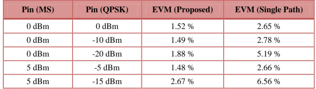
Concerning the measurement instrumentation used to characterize SDR/CR systems, some improvements have to be made in order to develop a synchronous instrument that will characterize analog-digital RF front-ends rapidly, automatically, and with impedance-mismatch correction. For instance, such an instrument would ideally provide information such as error vector magnitude for different types of modulation, adjacent channel power ratio for different technologies, and can be able to test multi-standard multiband radio configurations.
Chapter 3 – Wideband Nonlinear Behavioral Modeling
Practical SDR/CR architectures for receivers and transmitters will require a correct characterization and modeling of the RF front-end as a way to optimize the performance by constructing digital equalizers that would increase the receiving signal quality and, thus, maximize dynamic range, bandwidth, and so on. Moreover, the simulation of such complex architectures (entire receiver and transmitter RF front-ends) is quite computer intensive, mainly when the objective is to simulate RF signals modulated with high bandwidth excitations. Thus, the construction of accurate behavioral models for practical designs, accounting with single and multi-carrier signals, will facilitate the simulation and on the optimistic vision provide a faster time to market for the developed systems.
The chapter is supported in paper [C2] for the initial contributions on BPSR modeling, in paper [J2] for contributing with an improved behavioral model for BPSRs and paper [C3] for contributions on the multi-carrier modulated signals modeling subject.
3.1
Behavioral Modeling of Bandpass Sampling Receivers
Having in mind the receiving architectures previously discussed in chapter 2.1 (above), one of the most promising for SDR/CR applications is the BPSR design (Fig. 2.3) because of its approximation to the initial idea from Mitola [2]. This architecture is also becoming a feasible and practical solution due to the constant advancements achieved in ADCs.
In this manner, the focus of this section is to give a more detailed overview of the BPSR architecture operation and then propose a suitable wideband behavioral model, accompanied by the respective parameter extraction procedure, to cover RF/IF and baseband frequency responses, within the first and over several different NZs. Finally, the proposed behavioral model will be validated in different NZs using a common modulated signal as excitation.
The key element of BPSR architecture is the ADC component (commonly in a pipeline structure) that contains a sample-and-hold circuit, which in theory allows all of the energy from DC to the input analog bandwidth of the ADC to be folded back to the first NZ. This process occurs without any mixing down-conversion because a sampling circuit is
somehow replacing the mixer module. Indeed, this behavior will allow an RF signal of higher frequency to be sampled by a much lower clock frequency. The basic concept is depicted in Fig. 3.1, in which it is observed that all the input signals present in the allowable bandwidth of the sampling circuit are folded back to the first NZ. This folding process occurs for all the available signals at the input of the circuit but also for any nonlinearity that may be generated previously or even in the particular sampling circuit.
Thus, in order to better understand the operation of the explained BPSR in different NZ’s let us assume a BPSR sampled by a clock of 100 MHz and excited firstly by a signal excitation present in the first NZ (e.g. 14 MHz) and then by a signal excitation situated in the second NZ (e.g. 78 MHz). Consider as an example a third-order nonlinear system, for the first excitation frequency and taking into account the frequency folding phenomena, the fundamental and respective harmonics will fall within this same 1st NZ. However, the same will not happen for the second excitation frequency, where the baseband will fall on the first NZ, the fundamental and 2nd harmonic will fall in the 2nd and 4th NZ’s, respectively, and are folded back in the reversed way. The 3rd harmonic will fall in the 5th NZ and is folded back in the normal mode. Therefore, to describe the nonlinear behavior of such architecture, a huge bandwidth should be covered and accompanied by different dynamic effects, which is represented by different memory lengths in the nonlinear model.
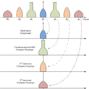
Fig. 3.1 – Process of folding that occurs in the sample-and-hold circuit showing the folding and overlapping of signals in the first NZ.
3.1.1 Proposed Nonlinear Behavioral Model
The last section confirmed that the produced behavioral model should be wideband and take into account the NZ where the signal is sampled in a way to effectively represent the BPSR nonlinear behavior. Additionally, several spectral components may appear in the first NZ case of the low-frequency baseband nonlinearities (defined by an even-order nonlinear product), with high-frequency components also possibly appearing at higher NZs where they are folded back to the resultant ADC bandwidth. This will impose conditions where the dynamic response of the BPSR will have time constants of highly different orders, with some at the RF time frame and others inside the baseband time frame.
So, an appropriate behavioral model that produces the required mathematical description for describing the nonlinear behavior of the BPSR may be supported on the Volterra series theory [61], due to its good performance in this type of mildly nonlinear scenarios. The Volterra series conditions represent a combination of linear convolution and nonlinear power series providing a general structure to model nonlinear systems with memory. As such, it can be used to describe the relationship between the input and output of the addressed BPSR, which may present a nonlinear behavior having memory effects. This relationship can be written as:
0 1 1 1, , ) ( ) ( ) ( ) ( n n n in in n n τ τ x t τ x t τ dτ dτ h t y (3.1)where xin(t) and y(t) are the input and output signal waveforms, respectively, and hn(τ1,…,τn) is the nth order Volterra kernel.
The applicability of such an RF time-domain Volterra series model to account with all these nonlinearities at once is complex because of the complicated model structure, which leads to an exponential increase in the number of coefficients for higher degrees of nonlinearities and memory lengths. Furthermore, the overall system description can behave very differently because, for instance, the even-order coefficients can generate signals at very high frequencies (such as in the case of the second harmonic) and at baseband frequencies near DC. In that sense, the Volterra approach as presented in (3.1) is not optimum for this situation since it uses the same descriptor for the second harmonic as for the baseband responses and thus does not provide the required flexibility. In fact, this problem was observed in the work presented in [C2], where a good approximation was
achieved at higher frequencies but it had some problems at lower frequencies and vice versa. To overcome this issue the Volterra series model can be applied in a low-pass equivalent format [62], in which a selection of each nonlinear cluster (baseband, fundamental, second harmonic, etc.) is firstly made and the respective complex envelope is then digitally obtained. As a result, the Volterra low-pass equivalent behavioral model is applied individually to each complex envelope cluster, taking into consideration the nonlinearity that has originated it. Actually, it can be seen as a model extraction based on the envelope harmonic balance method, where each cluster is addressed individually [63]. This low-pass equivalent conversion is exemplified in Fig. 3.2, which considers a third-order degree nonlinear scenario.
Fig. 3.2 – Diagram of the low-pass equivalent conversion of each cluster.