C
ONCEPTION
D
ESIGN AND
S
TRUCTURAL
A
NALYSIS OF
M
OVABLE
B
RIDGES
The Case Study of Great Yarmouth Third Crossing
A
NAB
EATRIZE
STEVESR
AMOSDissertação submetida para satisfação parcial dos requisitos do grau de
MESTRE EM ENGENHARIA CIVIL —ESPECIALIZAÇÃO EM ESTRUTURAS
Orientador: Professor Doutor Humberto Salazar Amorim Varum
Coorientador: Doutor Pedro Gonçalo Faustino Marques
M
ESTRADOI
NTEGRADO EME
NGENHARIAC
IVIL2016/2017
DEPARTAMENTO DE ENGENHARIA CIVILTel. +351-22-508 1901 Fax +351-22-508 1446 [email protected]
Editado por
FACULDADE DE ENGENHARIA DA UNIVERSIDADE DO PORTO
Rua Dr. Roberto Frias 4200-465 PORTO Portugal Tel. +351-22-508 1400 Fax +351-22-508 1440 [email protected] http://www.fe.up.pt
Reproduções parciais deste documento serão autorizadas na condição que seja mencionado o Autor e feita referência a Mestrado Integrado em Engenharia Civil - 2016/2017 -
Departamento de Engenharia Civil, Faculdade de Engenharia da Universidade do Porto, Porto, Portugal, 2017.
As opiniões e informações incluídas neste documento representam unicamente o ponto de vista do respetivo Autor, não podendo o Editor aceitar qualquer responsabilidade legal ou outra em relação a erros ou omissões que possam existir.
To my mother and brothers,
“Every Master was once a beginner. Every pro started as an amateur. Every icon began as an unknown.” Robin Sharma
ACKNOWLEDGMENTS
In first place I would like to thank my mother for all the unconditional support she has given me throughout my life and especially in college years. To my brothers for being my best friends and supporting me when I need.
To Professor Humberto Varum for making this international experience possible and with it not only improve and develop my professional knowledge but also allowing me to have the best personal experience that I have ever had.
To Engineer Pedro Marques for encouraging me throughout the all process of my dissertation and internship. His dedication, guidance and feedback were essential for my good performance and I thank you for his willingness to review all my ideas and documents.
To my co-workers at Mouchel/WSP, who have provided the best working environment and helped me through all the problems I encountered throughout my internship. I would like to particularly acknowledge Sam Akerstrom and Aram Hassan for all the guidance and support given throughout the project of GYTC.
To my “sisters” Mariana and Claudia for their friendship and care. I could not have asked for better friends.
To Marta, that was one of my main supports in my Erasmus journey. This experience gave me more than professional and personal growth, gave me a friend for life.
To my friends for being with me in the best and worst moments of my life, with them I could go through the challenges of life with a smile on my face.
RESUMO
Pontes móveis começaram a ser construídas desde tempos primórdios e numerosas pontes de diferentes tipos e materiais foram construídos até o presente. Com a evolução dos materiais e dimensões dos navios, o que, consequentemente, trouxe maior tráfego de navegação, o design de pontes móveis teve que melhorar constantemente.
Ao contrário das pontes fixas, as pontes móveis são uma combinação de dois designs técnicos, estruturais e mecânicos/elétricos/hidráulicos que devem estar interligados ao longo de todo o processo de design, requerendo, portanto, uma ampla gama de conhecimento e pessoas envolvidas.
O objetivo desta dissertação é descrever a metodologia e os principais aspetos que exigem atenção no início da conceção de qualquer projeto de pontes móveis. Além disso, também se descreve alguns problemas que foram analisados com o intuito de perceber como abordá-las à medida que o projeto progride.
Mostra-se que uma decisão sobre o tipo de ponte é muitas vezes governada pelo desempenho operacional da ponte, considerando a navegação e o tráfego rodoviário, e não da própria conceção estrutural da ponte.
No final, foi possível realizar um projeto conceptual de um caso de estudo real, realizado em ambiente empresarial na empresa Mouchel Consulting/WSP e selecionar o melhor design em relação a todos os requisitos e restrições impostas. Por conseguinte, foi estabelecido que uma ponte móvel basculante era o esquema recomendado e foram realizados cálculos preliminares para atestar a sua viabilidade e os desenvolvimentos futuros para a possível construção.
Durante a fase de projeto preliminar do caso de estudo, foi investido muito tempo em aspetos estruturais importantes, tais como: o tipo de bloqueio e o seu efeito sobre a articulação entre as duas folhas; e a presença e localização dos aparelhos de apoio para cargas variáveis, com impacto direto na distribuição de cargas e reações nos suportes. Estes dois aspetos foram identificados como os mais críticos para design de pontes basculantes e uma discussão foi dedicada ao seu impacto no comportamento estrutural deste tipo de pontes. Conclui-se que, ainda é necessário alguma discussão em futuras abordagens do projeto.
ABSTRACT
Movable bridges started to be built ever since early times and numerous bridges of different types and materials were built up until now. With the evolution of materials and development of ships dimensions, which consequently brought higher navigation traffic, the design of movable bridges had to constantly improve.
Contrarily to fixed bridges, movable bridges are a combination of two technical designs, structural and mechanical/electrical/hydraulic design which have to be interconnected throughout the whole project design process, having therefore a wider range of knowledge and professionals involved.
The objective of this dissertation is to describe the methodology and key aspects that require attention at the early conceptual stage of movable bridge designs followed by preliminary design. In addition, different issues were also analysed to understand how to address these as the project progresses. It is shown that a decision regarding the type of bridge is often governed by operational performance of the bridge considering navigation and road traffic rather than the structural conception of the bridge itself.
In the end, it is possible to undertake a conceptual design of a real case study, carried out in the company
Mouchel Consulting/WSP and select the best design regarding the all the requirements and restrains imposed. It was therefore established that a bascule movable bridge is the recommended design and preliminary calculations were carried out to attest the feasibility and future developments for possible construction.
During the preliminary design stage of the case study much time was invested on important structural aspects such as: the type of lock and its effect on the articulation between the two leaves; and the presence and location of the live load bearings with direct impact on loads distribution and support reactions. These two aspects were identified as critical plus the design of bascule bridges and significant discussion was dedicated to their impact on the structural behaviour of this type of bridges. It is concluded that further discussions are still required in future design approaches.
TABLE OF CONTENTS ACKNOWLEDGEMENTS ... i RESUMO ...iii ABSTRACT ... v
1. INTRODUCTION
... 1 1.1. PREFACE ... 1 1.2. OBJECTIVES ... 2 1.3.APPROACH ... 22. HISTORY AND TYPES OF MOVABLE BRIDGES
... 52.1.BACKGROUND ... 5
2.1.1.EARLY TIMES ... 5
2.1.2. MODERN TIMES ... 8
2.1.3.LAST TENDENCIES ... 9
2.2.TYPES AND FEATURES OF MOVABLE BRIDGES ... 10
2.2.1.BASCULE BRIDGES ... 11
2.2.1.1. Types of Bascule Bridges... 12
2.2.2. SWING BRIDGES ... 20
2.2.3.VERTICAL LIFT BRIDGES ... 22
3. MOVABLE BRIDGE CONCEPTUAL DESIGN
... 273.1.GENERAL ... 27
3.2.METHODOLOGY ... 29
3.3.DEMANDS ... 31
3.4.STRUCTURAL ANALYSIS ... 34
3.4.1.DESIGN CRITERIA ... 34
3.4.2.STANDARDS AND SPECIFICATIONS ... 34
3.4.3.CONSTRUCTIVE MATERIALS ... 34
3.4.5.2. Proportions ... 41
3.4.6.STRUCTURAL BEHAVIOUR AND LOAD PATHS ... 42
3.4.6.1. Bascule Bridges ... 42
3.4.6.2. Swing Bridges ... 44
3.4.6.3. Vertical Lift Bridges ... 46
3.4.7.MACHINERY SYSTEMS ... 47
3.4.7.1. Bascule Bridges ... 48
3.4.7.2. Swing Bridges ... 50
3.4.7.3. Vertical Lift Bridges ... 52
3.5.OPERATING MECHANISM DESIGN ... 53
3.6.SAFETY DESIGN ... 54 3.6.1.BRIDGE OPERATION ... 54 3.6.2.TRAFFIC CONTROL ... 55 3.6.3.SHIP COLLISION ... 56 3.7.BUILDABILITY ... 56 3.8.MAINTENANCE ... 57
4. CASE STUDY: GREAT YARMOUTH THIRD RIVER
CROSSING
... 594.1.BACKGROUND ... 59
4.2.SITE DESCRIPTION AND CONSTRAINTS ... 60
4.3.NAVIGATION TRAFFIC ... 62
4.4.DESIGN CONSIDERATIONS ... 62
4.4.1.BRIDGE LOCATION... 62
4.4.2.GEOMETRY –ALIGNMENTS AND CLEARANCES ... 64
4.4.3.DESIGN SERVICE LIFE ... 65
4.5.MOVABLE BRIDGE OPTIONS ... 65
4.5.1.OPTION 1–BASCULE BRIDGE ... 66
4.5.1.1. Leaf Types ... 67
4.5.1.2. Structure Type VS Opening Span ... 67
4.5.2.OPTION 2–SWING BRIDGE ... 68
4.5.2.1. Leaf Types ... 69
4.5.3.OPTION 3–VERTICAL LIFT BRIDGE ... 70
4.6.LOADS ... 71
4.6.1.PERMANENT LOADS ... 71
4.6.2.WIND ... 71
4.6.3.SHIP IMPACT LOADS ... 72
4.6.4.SNOW ... 73 4.6.5.TRAFFIC LOAD ... 73 4.6.6.TEMPERATURE ... 73 4.6.7.HYDRODYNAMIC LOADS ... 73 4.6.8.DYNAMIC LOADS ... 73 4.7.AERODYNAMIC CONSIDERATIONS ... 73 4.8.SUPERSTRUCTURE TYPES ... 74 4.8.1.STRUCTURAL TYPES ... 74 4.8.2.MATERIALS ... 74 4.9.SUBSTRUCTURE TYPES ... 74 4.9.1.STRUCTURAL TYPES ... 74 4.9.2.MATERIALS ... 75 4.10.FOUNDATIONS TYPES... 75
4.10.1.GEOTECHNICAL CONSIDERATION –84M CLEAR SPAN ... 77
4.10.2.GEOTECHNICAL CONSIDERATION –50M CLEAR SPAN ... 78
4.11.SHIP COLLISION ... 79
4.12.OTHER CONSIDERATIONS ... 79
4.12.1.AESTHETICS ... 79
4.12.2.BRIDGE OPENINGS AND TRAFFIC CONTROL ... 80
4.12.3.OPERATING MECHANISM ... 81
4.12.4.BUILDABILITY ... 81
4.12.4.1. Substructure ... 81
4.12.4.2. Superstructure ... 82
4.12.5.COSTS ... 82
4.12.6.‘ICONIC’BRIDGES ... 82
4.13.SELECTION -RECOMMENDED ... 84
4.14.1.1. Highway Layout ... 85
4.14.1.2. Form of Deck ... 86
4.14.2.OPERATING MECHANISM LAYOUT... 88
4.14.3.BACK SPAN ARRANGEMENTS ... 90
4.14.4.ARTICULATION ARRANGEMENTS ... 92
4.14.4.1. Tail and Nose locks ... 92
4.14.4.2. Live load supports ... 93
4.14.5.SUBSTRUCTURE AND FOUNDATIONS... 93
4.14.6.SHIP COLLISION PROTECTION ... 93
4.14.7.OPERATION OF THE STRUCTURE ... 84
4.14.8.ANALYSIS ... 94
4.14.8.1. Permanent Loads ... 95
4.14.8.2. Traffic Loads ... 95
4.14.8.3. Wind ... 97
4.14.8.4. Snow ... 98
4.14.8.5. Combinations and Load factors ... 99
4.14.8.6. Preliminary Calculations ... 101
4.14.8.7. Midas Model ... 101
4.14.8.8. Capacity Calculations ... 103
4.14.8.9. Pier and Foundations ... 105
4.14.9.BUILDABILITY ... 108
4.14.10.MAINTENANCE AND INSPECTION ... 109
5. CONCLUSION AND FUTURE DEVELOPMENTS
... 1115.1.CONCLUSION ... 111
5.2.FUTURE DEVELOPMENTS ... 112
REFERENCES ... 113
INDEX OF FIGURES
Fig.2.1 - Sketch of Xerxes Bridge... 5
Fig.2.2 - Typical ‘draw’ Bridge ... 5
Fig.2.3 - Oldest ‘draw’ Bridge ... 5
Fig.2.4 - Da Vinci sketch of Swing Bridges ... 6
Fig.2.5 - South Park Bridge ... 8
Fig.2.6 - Gateshead Millennium Bridge ... 9
Fig.2.7 - Typical Bascule Bridge – Trunnion type ... 10
Fig.2.8 - Double-leaf Scherzer bascule Type ... 12
Fig.2.9 - Half-through single leaf Scherzer bascule Type ... 12
Fig.2.10 - Through truss single leaf Scherzer Bascule Type ... 12
Fig.2.11 - Rall bascule bridge, Illinois River ... 13
Fig.2.12 - Simple trunnion bascule bridge ... 14
Fig.2.13 - Strauss Heel-Trunnion ... 15
Fig.2.14 - Strauss Overhead Counterweight ... 16
Fig.2.15 - Strauss underneath Counterweight ... 17
Fig.2.16 - Centre bearing swing bridge ... 20
Fig.2.17 - Rim bearing swing bridge... 20
Fig.2.18 - (a) Mechanical centre bearing (b) Mechanical rim bearing... 21
Fig.2.19 - Tower drive vertical lift system ... 22
Fig.2.20 - Span drive vertical lift system ... 23
Fig.2.21 - Connected tower drive vertical lift system... 24
Fig.2.22 - Pit drive vertical lift system ... 24
Fig.3.1 - Main bridge lifecycle ... 27
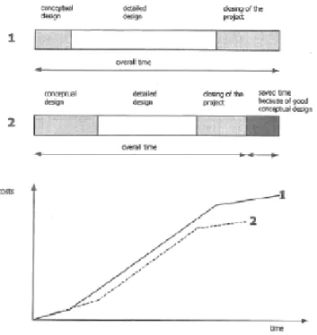
Fig.3.2 - Potential savings in during a project ... 28
Fig.3.3 - Process for conceptual design ... 29
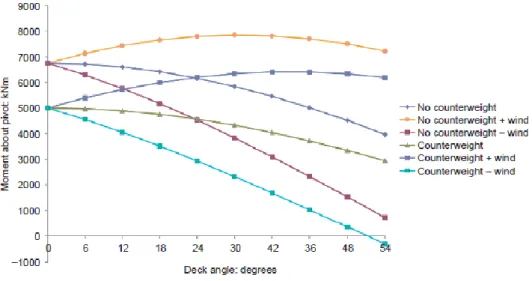
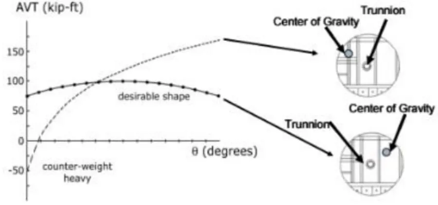
Fig.3.4 - Graph of moment about pivot compared with angle of deck inclination ... 35
Fig.3.5 - Balance bascule leaf ... 36
Fig.3.6 - Comparison of different torque during operation of a bascule bridge ... 37
Fig.3.7 - Comparison motions between trunnion and rolling bascules bridges ... 37
Fig.3.8 - (a) Bridge Corey Causeway (b) Rectangular open grid ... 39
Fig.3.11 - (a) Spokane Street Swing Bridge (b) Concrete deck ... 40
Fig.3.12 - (a) Bridge Han Lammersbrug (b) Aluminium deck ... 41
Fig.3.13 - Initial sizing – truss (not at scale) ... 41
Fig.3.14 - Initial sizing – truss (not at scale) ... 42
Fig.3.15 - Shear and moment locks arrangements: (a) shear lock; (b) moment lock ... 42
Fig.3.16 - Schematization of real behavior double leaf Bascule Bridge with active mid-span shear locks ... 43
Fig.3.17 - Analogy schematization of double leaf Bascule Bridge with active mid-span shear locks ... 43
Fig.3.18 - Simplified schematization of double leaf Bascule Bridge with active mid-span shear locks ... 43
Fig.3.19 - Displacement of adjacent cantilever leaf ... 43
Fig.3.20 - Analogy schematization of double leaf Bascule Bridge with active mid-span moment locks ... 44
Fig.3.21 - (a) Stresses diagram of rim bearing Swing bridge (b) Load Paths of rim bearing Swing Bridge closed position ... 45
Fig.3.22 - (a) Stresses diagram of centre bearing Swing bridge (b) Load Paths of centre bearing Swing Bridge closed position ... 45
Fig.3.23 - Deflection diagram of centre bearing swing bridge ... 46
Fig.3.24 - (a) Stresses diagram of Cable-stayed Swing bridge (b) Load Paths of Cable-stayed Swing Bridge ... 46
Fig.3.25 - Illustration of the majority of machinery for double leaf bascule types... 48
Fig.3.26 - Illustration of the majority of machinery for single leaf bascule types ... 49
Fig.3.27 - Illustration of the centre supports ... 50
Fig.3.28 - Illustration of the majority of machinery for swing bridges ... 50
Fig.3.29 - Illustration of one arrangement of the end supports ... 51
Fig.3.30 - Illustration of the majority of machinery for vertical lift bridge ... 52
Fig.3.31 - Section of a bascule bridge with a mechanical drive mechanism ... 53
Fig.3.32 - Section of a bascule bridge with hydraulic cylinders mechanism ... 54
Fig.3.33 - Plan of overhang and elevation of Barge Bow ship collision with pier ... 56
Fig.4.1 - Great Yarmouth port ... 59
Fig.4.2 - Great Yarmouth... 61
Fig.4.3 - Area of interest and Potential locations ... 63
Fig.4.4 - Alignment of the proposed bridge ... 64
Fig.4.6 - Swing bridge option – 50m clear span ... 69
Fig.4.7 - Vertical lift bridge option – 84m clear span ... 70
Fig.4.8 - Value of fundamental basic wind velocity before the altitude correction is applied ... 72
Fig.4.9 - Geological Map of Great Yarmouth District ... 77
Fig.4.10 - Example of fendering system ... 79
Fig.4.11 - Bascule ‘Iconic’ Bridge ... 83
Fig.4.12 - Vertical Lift ‘Iconic’ Bridge ... 83
Fig.4.13 - Elevation of the proposed bascule bridge ... 85
Fig.4.14 - Layout of the proposed bascule bridge ... 86
Fig.4.15 - Box girder arrangement deck ... 86
Fig.4.16 - I beam girder arrangement deck ... 87
Fig.4.17 - Trapezoidal box girder arrangement deck ... 87
Fig.4.18 - Trapezoidal box girder arrangement deck ... 87
Fig.4.19 - Bascule bridge with fixed pivot point... 88
Fig.4.20 - (a) Bascule bridge with fixed pivot (b) Bascule bridge with fixed pivot and counterweight ... 89
Fig.4.21 - Bascule bridge with fixed pivot and hanging counterweight ... 89
Fig.4.22 - Back span straight joint arrangement ... 90
Fig.4.23 - Back span straight joint with kentledge below slab arrangement ... 91
Fig.4.24 - Back span stepped joint arrangement ... 91
Fig.4.25 - Back span stepped joint with kentledge below slab arrangement ... 91
Fig.4.26 - Diagram of half double leaf trunnion with live load shoes ... 93
Fig.4.27 - Plan of the bridge showing the Knuckle walls with fendering steel system ... 94
Fig.4.28 - Application of load model 1 ... 95
Fig.4.29 - Configuration for the SV80 vehicle loads for load model 3 ... 96
Fig.4.30 - Assessment of groups of traffic loads (characteristic values of the multi-component action) ... 96
Fig.4.31 - Longitudinal load ... 97
Fig.4.32 - Directions of wind actions on bridges ... 97
Fig.4.33 - Results of bending diagram ... 98
Fig.4.34 - Equation NA.1 of characteristic ground snow ... 98
Fig.4.35 - Results of combination 1 ... 100
Fig.4.39 - Model of half bridge ... 102
Fig.4.40 - Final deck arrangement: (a) At Support (b) At Mid-span ... 103
Fig.4.41 - Displacement of a cantilever with a distributed force ... 104
Fig.4.42 - Displacement of the bridge model (exaggerated) ... 105
Fig.4.43 - Main dimensions of the main pier ... 106
Fig.4.44 - Pile dimensions of the main pier ... 107
Fig.4.45 - Design values for crag formation ... 108
INDEX OF TABLES
Table 2.1 - Summary of features of bascule bridge types ... 19 Table 3.1 - Design demands ... 32 Table 3.2 - Main detailed requirements ... 55 Table 4.1 - Components design service life ... 65 Table 4.2 - Summary of ground model ... 76 Table 4.3 - Appraisal costs ... 82 Table 4.4 - Design Documents ... 95 Table 4.5 - Results of wind calculations ... 97 Table 4.6 - Results of snow calculations ... 99 Table 4.7 - Longitudinal load (only with gr1)... 99 Table 4.8 - Longitudinal breaking/acceleration forces ... 99 Table 4.9 - Results of load combinations ... 100 Table 4.10 - Summary of load cases (ULS) for the deck at support ... 103 Table 4.11 - Final sizes... 104 Table 4.12 - Summary of capacity check for the pier at and top of haunch ... 105
SYMBOLS,ACRONYMS AND ABBREVIATIONS
k – stiffness
sk - characteristic ground snow load fck - Characteristic compressive strength fy – Yield strength of steel
Ψ – Factor applied to accompanying action - Partial factor (applied to action)
MEd – Applied bending moment MRd – Bending moment capacity Ψ*sv – Reserve factor (BD 101/11) VEd – Applied shear
VRd –Shear capacity WL – Wheel loading δ – displacement
Ni – Axial load on an individual pile N – vertical load on the pile group Mx – Bending moment in x direction My – Bending moment in y direction Qs – compressive resistance
α – factor related to bored surface Cu – undrained shear strength As – Area of pile surface Qb – base resistance
qb – characteristic values of base resistance
Ab – Area of pile base
QT – compressive resistance of a pile
Fs – Safety factor p – load
l – length
n – number of piles
NSPT – number of blows in the standard penetration test
AASHTO – American Association of State Highway and Transportation Officials AREMA – American Railway Engineering and Maintenance-of-Way Association NEN - Nederlands Normaisatie Instituut
DIN - Deutsches Institute fur Normung
GYTRC – Great Yarmouth Third River Crossing LEP - Local Enterprise Partnership
UK – United Kingdom
M&E – Mechanical & Electrical FRP - fibre-reinforced polymers LM – Load model
TS – Tandem System
UDL – Uniformed Distributed Load SV – Special vehicle
STGO – Special Types General Order EN – Eurocode
NA – National Annex ULS – Ultimate limit state SLS – Service limit state DL – Dead loads EQU – equilibrium STR – structure GEO – geotechnical 2D – 2 dimensions 3D – 3 dimensions
1
INTRODUCTION
1.1. PREFACE
With the construction evolution and consequent roads and railways progressive development, emerged the need for the population to make crossings, not only to overcome geographical obstacles, but also to reduce the necessary travel time. However, one of the major problems until today has been the crossing of navigable waters. As one of the key means of global transport, sea-river navigation could not be less important than the construction of bridges, which would affect its course. It was then necessary to find a solution that would enable navigation of rivers and at the same time their crossing. Since building bridges with adequate clearance for the passage of ships required a more elaborate work in terms of very high inclination, movable bridges became the most viable solution to this dilemma, despite all the challenges on their design.
The term movable, refers to the type of bridge that changes position, vertically or horizontally, enabling then the passage of boats/ships into rivers and/or navigable channels when necessary.
Nevertheless, movable bridges have not always had this purpose. In the Middle Age, these were used for protection against enemy’s armies. The so-called drawbridges in medieval castles were designed onto the surroundings of castles so that, with or without counterweights, these were lifted through the upper rotation of sheaves, operated with chains or ropes. These bridges, after elevation, were intended to serve as shield against invasions and entry obstruction.
Since ancient times, this type of bridges has undergone a great evolution, not only in its purpose, but also in its techniques and construction design, due to the development of a wide number of technologies and construction materials.
The design of movable bridges, have primary explored over the last century the typical three types of movable bridges, bascule; swing; and vertical lift. Regardless of this, innovative solutions are increasingly taking form.
As they are of a complex combination of structural, mechanical, electrical and hydraulic systems, movable bridges have some issues and associated special requirements and are more prove to experience significantly higher deterioration and declining than regular fixed bridges. Thus, a good strategy design
and maintenance requirements are of extremely importance.
In this sense, the elaboration of a specific and good technical approach of the design is needed. This approach aims at the conception (early stages) of the design, enhancing communication between the
The Design Approach developed during this study establishes and revisits design requirements for movable bridges to minimize any potential problem that is susceptible to cause failure of the operation of a movable bridge. It helps, therefore, establishing the basic concepts to provide all bridge components (of different domains) with reasonable capacity against loads and operation reability.
1.2. OBJECTIVES
The aim of this work was to develop an enhanced approach about the conceptual and preliminary design of movable bridges. Different types of movable bridges and their design features were investigated in order to then enable the right approach to the design in question. It was then carried out a real case study (Great Yarmouth Third Crossing) as part of an internship done in the company Mouchel Consulting/WSP in Manchester, with the main purpose to provide a final recommendation for the three main types of movable bridges herein studied.
The main objectives of the present documents are:
Make a brief historical context of movable bridges, identifying structural typologies and different main characteristics;
Present the fundamental features and approaches of designing a movable bridge; Improve the ability of interconnecting the different fields considered in design;
Describe in detail the case study of conceptual and preliminary design stages of a movable bridge over a navigable river.
1.3.APPROACH
Taking into account the objectives described before, the present work was organised in five chapters. The content of each of them is summarized below:
Chapter 1 – Presents a brief introduction about movable bridges and their design, giving particularly attention to the need for a detailed knowledge of the unique specifications of these types of structures design. Identifies the main purposes of the dissertation and presents the chapters approach.
Chapter 2 – Begins with a brief historical research of the construction of movable bridges relating with their construction time to the structural type and materials used. Afterwards, it is presented a learning of the different types of movable bridges and their most important features.
Chapter 3 – Presents a methodology and a description of the most important details, issues and common mechanisms that have to be taken into account when a conceptual and preliminary design is carried out.
Chapter 4 – From the information studied and developed in the previous chapters, a real case study is assessed regarding a conceptual and preliminary design, in the United Kingdom. In this chapter are described the difficulties of implementing the project design and the optimal approach that led to the final solution.
Chapter 5 – Final conclusions and comments are made about the work developed here and some guidelines are also proposed for the development of possible future work.
In addition, this dissertation presents, an appendix with the preliminary calculations carried out and the results of a finite element model created on the program Midas Civil to confirm the feasibility of the final structure recommendation.
An appendix is also presented with some real examples of the different types of movable bridges described in chapter 2.
2
HISTORY AND TYPES OF MOVABLE
BRIDGES
2.1. BACKGROUND
2.1.1.EARLY TIMES
It is thought that the first movable bridges to be built were in Ancient Egypt, circa 1855 BC, in the 12th Egyptian Dynasty. According to Edward H. Knight (1876), the first allusion to movable bridges was made in Egyptian monuments, such as palaces and temples, where there would be illustrative drawings of these bridges around castles and fortified cities. (Hovey, 1926) During the reign of Ramsess II in 1355 BC, the use of so-called floating bridges on the Nile River was already mention. (Mahmoud, 2003) Around 460 AD, Nitocris, the queen of Babylon had a bridge built on the Euphrates River, one of the main elements of the Tigris-Euphrates system, which defined Mesopotamia. According to the stories of Herodotus, this bridge was built with pillars of stone blocks connected with iron and lead and spans of wooden platforms, wich would be removed at nigth to prevent the passage of people from both shores. (Hovey, 1926)
The tradition of building movable bridges was probably exported from these regions to Syria, with examples circa 1100, and then to Europe, but some examples are dated before the year 1000 in China. [Mahmoud, 2003] Otis Ellis Hovey, noted that most likely around the third century and into the middle of the sixth century, the Chinese have used movable bridges in their channels, as they have developed an unusual skill in engineering since very early. (Hovey, 1926)
Some centuries later, in 621 AD, in the Roman Empire, was built the first recorded movable Roman Bridge, by Ancus Martius. This was made up of planks of wood and according to some writers had a drawbridge. (Hovey, 1926)
The first and perhaps the most common movable bridges were, as already mentioned, pontoon bridges. These were mostly used in military expeditions and were built by piles of wood, with small vessels, tied together strategically so that they could be moved or swung to allow a navigable passage. An example of this is the Darius boat bridge over the Bosphorus Thracian River in Turkey, which connects Europe to Asia, and the Xerxes Bridge over the Hellespont passage, now called Dardanelles, in Turkey. (Hovey, 1926)
Fig. 2.1 – Sketch of Xerxes Bridge (Unknown, n.d.)
The Romans quickly developed the construction and design of fixed arch bridges, but it is difficult to trace the progress of movable bridges to the beginning of the Christian Era. (Hovey, 1926)
Later, during the Middle Ages, the drawbridge, described at the beginning of the chapter 1, was perhaps the most common bridge, being used as a passage in the closed position, but also when in open position, as a protective castle barrier. (Hovey, 1926) The most typical set up would be a lift movable bridge just outside the gate, comprising a wooden plataform with a pinered articulation at the edge of the gate. This would enable the plataform to rotate about this axle, making this type of bridge the processor of bascule bridges. This lifting, as can be seen in figure 2.2, was carried out throught ropes or chains linked to a reel, in a dramber over the entrance. Counterweights were sometimes used to balance the bridge and reduce the required force for this operation. (Koglin, 2003) A fairly ingenious alternative system can also be seen on the right-hand side to replace the previous conventional drawbridge. This mecanism works by a top frame (L) being raised, pivoted by a support (M) and connected by chains to the end of the bridge. The particularity of this bridge is the existence of a counterweight falling in a curved trajectory to a lower level. The structure would always be in balance throughout its opening process. This will later be known as the Bélidor type bridge. According to Ottis Hovey, the oldest bridge of this style is the bridge in the fortress of Bonifacio in Corsica.
Since the 14th century until the end of the 16th century, in the Renaissance, which was marked by very distinguished transformations in the area of culture, science, art, economics, politics and religion, was born a period of great human minds and discoveries. Movable bridges were also an expression of this era and did not go unnoticed, where it is noteworthy the existence of several sketches on this subject, authored by one of the most remarkable minds of that time, Leonardo da Vinci. Many of these sketches are still preserved, and were published in the ‘Codice Atlantico’1. Figure 2.4 show sketches of Da Vinci
himself and it can be observed that, in the year 1500, the engineering of movable bridges, more properly swing bridges, was already well advanced. Figure 2.4 shows a design of swing bridges in which the rotation was operated by hand winches, through ropes connected to snacth-blocks. (Hovey, 1926)
Fig. 2.4 – Da Vinci sketch of Swing Bridges (Hovey, 1926)
Some sketches also show the development of some ideas of vertical lift bridges with counterweights. This period was very rich in terms of bridge construction developments and many of the projects and constructions undertaken at this time served as basis for many of the modern bridge constructions recently used in Europe and America.
Further types of movable bridges designs were developed and great skill was demonstrated by various engineers throughout their (designs) gradual evolution to modern times.
A new era of engineering was born at the invention of the steam engine by James Watt in 1769 and the introduction of the steam locomotive by George Stephenson, in 1829. These two inventions marked the production of energy and were responsible for the fast evolution of almost all forms of engineering. Movable bridges were no exception and their design and construction had a tremendous progress. Many types of movable bridges were developed at the time, but the swing type was the one that grew more in popularity and, hence, in development. Since creating power was expensive, it was thought that the swing type bridge was cheaper. This, because these bridges were of a simple design and were balanced to both sides, from an axis of rotation, located under its center of gravity, not being necessary the operation of raising and lowering. (Koglin, 2003)
Although the inventions referred previously, resulted in a vast increase of movable bridges construction, the followed boom of the railroad industry, in the mid-nineteenth century and the lorry industry after the First World War danwed a new start. (Ryall, Parke, & Harding, 2000) The fast pace of industrial growth has made it essential to find a way to cross rivers and active channels used by a variety of vessels of different sizes, so that road and rail traffic could travel without permanently interfering with the flow of any kind of traffic. This was a particular problem in expanding cities with important navigable waterways, so movable bridges were the answer. (Sloan, 2004) This industry boom has provided a boost to the metal and the development of the mass-manufacturing processes. This allowed the construction of lighter and stronger spans, longer bearings and more powerful engines. (Hall, Unknown)
2.1.2.MODERN TIMES
At the beginning of the 17th century, knowledge of the rotation of swing bridges through pivots with
centre bearings supporting devices was already visible. But it was only at the beginning of the 19th
century that british engineers developed pivots with rim bearing supporting devices which were capable of withstand the immense weight of large swing spans. Due to its simplicity, reliability and economy, the type of centre bearing prevailed over the more complex design and by the third decade of the 20th
century, this type almost replaced the rim bearing . At that time, engineers came to the conclusion to appreciate the advantages of this type of bridges over the most diverse forms of movable bridges. (Unknown, Unknown)
As Otis Hovey said in 1926, "when there are no restricting circumstances, a swing bridge is the simplest, best, and most economical type in first cost and maintenance". Not all engineers agreed with Hovey's statement of superiority of swing bridges. The bascule bridge had many followers throughout history. In the 20th century, George Hool, professor of Structural Engineering at the Wisconsin University,
vigorously supported the benefits of this type of bridge in both its 1924 and 1943 editions of Movable Bridges and Long-Span Bridges. This preference was mainly due to the fast opening of the bridge, causing the ship to pass through the river/channel more quickly. (Hool & Kinne, 1943) Despite supporting the swing bridge, Hovey acknowledged that the bascule bridge was superior when many parallel bridges had to be upright and when the waterways were too narrow. (Hovey, 1926)
The oldest construction of a modern bascule bridge dates back to 1894 with the construction of the Tower Bridge in London and Van Buren in Chicago. A number of bascules bridge designs have been developed and patented over the following decades. According to bridge engineer J.A.L Waddell: "they [the designs] are scientific, and they represent, probably, the best and most profound thought that has ever been devoted to bridge engineering", as he also patented a type of bascule bridge. (Waddell, 1916) During this period, two types of bascules bridges prevailed, the trunnion bascule and the rolling lift bascule. The trunnion, in its simplest forms, evolved from medieval drawbridges and was developed by European military engineers in the early 18th century. JAL Waddell states in his work “Bridge
Engineering” from 1926 that the bridge Michigan Avenue, in Buffalo, New York was the first major bascule bridge to be constructed. This type later evolved in the 19th and 20th centuries to two variations,
the simple trunnion or "Chicago" and the multiple trunnion or Strauss. (Hovey, 1926)
The simple trunnion, patented by the Chicago Bascule Bridge Company, was basically an improvement of the counterweights mechanism. The design of multiple trunnions was far much more complex, which in addition to the main, contained three secondary trunnions, and all connected by supports that form a rectangle when the span is closed and a parallelogram when the span is opened. (Hovey, 1926)
The rolling lift, maintaining the natural movement of the upward-swinging motion, evolved by adding an additional movement - the span retreated from the opening as it was lifted, thus providing even more clearance for navigation. This has been achieved by attaching the span to a beam segment, which tilts the span upward as it retreats in its track, simultaneously. Two early 19th century French bridges, built
in Havre and Bregere, were the predecessors of this type of bridges.
At the end of the 19th century, two variants of the rolling lift type were patented, Scherzer and Rall,
which will be studied in detail later in section 2.2. Developed in 1893 by William Scherzer, American engineer, held twelve patents for various variations of this type of bridge since 1893 to 1921, which became the most popular of all types until 1916. The first exemplar of this bridge was the Van Buren Street Bridge, located in Chicago, followed by many others, as this design resulted in the replacement of many movable bridges in England docks, such as Liverpool, Birkenhead and London. This movement occurred since its structure allowed to cross much larger channels than the other existing types at that time.
The Rall system, created and patented by Theodor Rall in 1901, was the other variant to be designed. The company who held the construction rights was Strobel steel Construction. One of the few bridges still existing of this form and perhaps most well-known is the Broadway bridge, in Portland, United States of America. This is also the largest span ever built of this type of system.
Until 1908, little progress was made in the building of vertical lifting bridges. As of this date, and approximately in the next two decades, was a great deal of interest from bridge engineers in this type of movable bridges, who have built about 70 movable vertical lifting bridges in America alone. This interest was held to be possible because of the varying amount of advantages these bridges entail. (Hool & Kinne, 1943)
2.1.3.LAST TENDENCIES
In the last two decades, the movable bridges technology has undergone changes very quickly, due mainly to the introduction of hydraulic machinerys and automatic controllers. Through these developments, it was possible to operate bridges easier and safer, using smaller machinery. (Mahmoud, 2003) But despite the great evolution of the constructive technical part, the aesthetics of modern bridges falls short. During the latest half of this century, no substantial innovation was made in this aspect, with several existing designs being characterized by repetitive and unattractive solutions. (Mahmoud, 2003)
Although this unattractive tendency, in recent years, some projects have distinguished themselves by their exceptionality, giving new hope to the design of movable bridges. This is mostly due to the use of advanced software available and sophisticated modeling, such as finite element models. The possibilities of determining the natural frequencies of the structures, with the availability of new high-performance materials, are allowing a world of new innovative solutions with incredible structural schemes, for instance the use of highly slender spans. (Mahmoud, 2003)
More recently, it has been proven that kinematics plays a much more important role in the design and analysis of this type of bridge than previously thought. Nowadays, there are already simulation models for complex kinematic mechanisms, allowing the engineer a much better control of the structural system with the type of elevation scheme. (Mahmoud, 2003)
Fig. 2.6 - Gateshead Millennium Bridge (Unknown, www.resimhayattir.com, n.d.)
2.2. TYPES AND FEATURES OF MOVABLE BRIDGES
As previously mentioned, movable bridges have had a huge record and evolution through the history of bridge engineering.
According to a study by C. C. Schneider (former president of the Society of American Engineers), in 1907, to expose movable bridges and establish their specifications, movable bridges were classified into six main types:
Bascule Bridges Vertical lift Bridges Swing Bridges Transporter Bridges Retractile Bridges Pontoon Bridges
It should be noted that some of these bridges can be subdivided due to their unique characteristics and are not restricted to those presented above, since they can be created to meet the specific conditions of the place in question.
In this paper work it only will be studied the three main and common types of movable bridges: Bascule, Vertical lift and Swing bridges.
2.2.1.BASCULE BRIDGES
The bascule bridges are based on the simple principle that if one end of the span is raised, the other one has to be lowered. The term bascule is generally applied to any type that moves through a fixed or movable axis, and those that move through a circular segment of beam.This occurs, by pivoting on a horizontal axis, at a certain angle. This pivot should be close to its center of gravity so that the weight on one side can be balanced by the weight of the other side. (Koglin, 2003)
The deck of these type of bridges may consist of one or two leaves that is a single span, or two symmetrical ones, which when in the close position, engage one another, ensuring that the two work together as one, causing their final deflection to be the same, when loaded. (Hovey, 1926)
The end of the bascule span is called the toe of the leaf, and the part of the span near the pivot point is called the heel of the leaf. This point, adjacent to both the approach span and deck, is supported by the bascule pier. Normally the counterweight is at the back end of the leaf and serves to balance the leaf about the trunnion. This is placed outside of the pier so that it is exposed. Such a design is used because is advantageous in that it minimizes the width of the pier and can resist uplift when there is traffic at the span. The trunnion, previously mentioned is used on many of these bridges and basically is a pivot on a shaft. First associated with cannon, an important military development, is normally used to describe a cylindrical protrusion used as a pivoting point that rotates while supporting a load. This is frequently thought incorrectly because the trunnion only rotates a fraction of a turn and never the full rotation. (Koglin, 2003) The operating machinery must be capable and ample enough to overcome the friction of all the trunnions and joints and support the mass of the moving leaf, counterweights and the rest of the structural members. Normally the weight of the counterweights are from two to three times bigger than the leaf, therefore be required a proportionately power by the machinery.
Fig. 2.7 - Typical Bascule Bridge – Trunnion type (Koglin, 2003)
The bascule bridge had a large development because of its many advantages, mentioned next:
Operation - Bascules do not need to be fully opened to allow small boats to pass, so the time for the operation is proportional to the sort of opening. This, comparing to swing bridges, that require a
It is also important to state that the bascule does not block the channel during operation, therefore it does not require occupation of river frontage like swing bridges. In narrow waterways, this is an essential issue. One of the most important vantages of bascule bridges is the no limitation of air draught when in open position.
Pier Considerations - For certain locations with narrows channels the piers can be the main consideration as these are smaller that the ones for swing bridges. The fendering system needed for protection of the piers and auxiliary spans can be shorter than for swing bridges. Bascules with underneath counterweights need a counterweight chamber (called main pier) below deck level.
Costs - Bascule bridges are very economical for medium range spans (10-50m) but can be built for any length.
Superstructure - The superstructure area limited to navigation span only and normally has a minimal visual impact when in closed position and significant visual impact when raised. Mechanically simple in single leaf form with no locking system required. As the leaf is raised more installed power is required than other movable bridges types to overcome the wind loading.
2.2.1.1.Types of Bascule Bridges
Bascules bridges can be categorised as in three main classes - rolling type, trunnion type (Chicago) and Strauss type. Any of these types may have either a single or a double leaf, being that for railroad traffic the single leaf is preferable, for it can be made to act as a simple span when closed and so a greater rigidity is guaranted.
1) Rolling bascule bridge
Scherzer Bascule Bridge
Rolling bascule bridges are generally refered as ‘Scherzer Bascule bridges’ due to is inventor and patents, and it is characterised by having at one end a cylindrical curved part that rolls upon tracks (usually in the form of a heavy girder) when the bascule leaf rotates open or closed. These curved part are usually designed by ‘segmental girders’. Slippage between the curved part treads and the running tracks is prevented by a teeth meshing that engage one another. (Berger, Healy, & Tilley, 2015) Due to their large size, many Scherzer rolling bridges incorporate counterweights made of cast iron or another dense material to reduce the size and the cost of the structure. This allows a reduction of wind resistence because it is possible the use of a smaller diameter of treads and consequently smaller segmental girders. (Koglin, 2003)
This type has the distinct advantage over other forms of movable bridges in making the navigation channel free for boats more quickly. Thus, since it translates away from the channel as it rotates open, the angle necessary to provide the same clearance as other bridges is much smaller. (Koglin, 2003) Three common types of Scherzer bascules include the deck double-leaf, the half-through single –leaf and the through single-leaf:
Fig. 2.8 – Double-leaf Scherzer bascule Type (Berger, Healy, & Tilley, 2015)
Fig. 2.9 – Half-through single leaf Scherzer bascule Type (Berger, Healy, & Tilley, 2015)
Fig. 2.10 – Through truss single leaf Scherzer Bascule Type (Berger, Healy, & Tilley, 2015)
Rall Bascule Bridge
Another variation of the rolling lift type, developed by Theodore Rall, is the Rall bascule bridge that combines rolling with longitudinal motion. The key feature is a trunnion that is set inside a roller that moves along a track.The combined movement can be explained by the example refered below, which is a diagram of an electrical railway bridge over the Illinous River, ate Peoria, Illinous.
Fig. 2.11 - Rall bascule bridge, Illinois River (Hovey, 1926)
The counterweight of the main girder which is connected to the pier by the swing strut D and turns on pins, does not required a pit to received is tail, since the centre of rotation is to far from the pier. One of the many features of the Rall type is that, when closed, is possible to remove and replace the pivoted rollers A, as they are released of all loads. The retreating motion of the leaf allows a minimum span length to achieve a clear waterway, however the shifting of the centre of gravity by the rollers disturbs the foundation pressures. Also, it has to be taken in account the weight contact between the rollers and the tracks and the friction between them, so it is necessary the finest design and material of this elements. (Hovey, 1926)
2) Simple Trunnion or ‘Chicago’ Bascule Bridge
Simple trunnion bascules main feature is the use of a system of heavy counterweights mounted on a frame at the end of the span. This allows the redution of the size of the mechanical power system components required to operate the bridge and in case of failure a marge of safety.
One of the characteristics of this bridge is that the part of the leaf that extends over the water is much longer than the part that is mounted on a frame. During the opening of the span, the counterweights and leaf weight are supported by trunnions carried in trunnion bearings attached to the piers and located approximately at the center of gravity of the entire mass. (Hool & Kinne, 1943)
Fig. 2.12 - Simple trunnion bascule bridge (Berger, Healy, & Tilley, 2015)
When the bridge is being operated, power is transmited to pinions that rolls on curved racks in one direction to open and on the other to close it. The trunnions bearings can be attached directly or indirectly to the masonry of the piers, being therefore possible the inexistence of piers. The frame were the counterweight fits should have elastic bumpers to absorb the shock, as showed in figure 2.12.
A big disadvantage of this type is that when it is needed a medium or long span bridge close to water level, is required large bascule pires with deep pits.This type has been topic of various discussions and research for the reason that it is possible to have various different systems capable of supporting the trunnions bearings. Although these counterweights are expensive to construct and requires a large area
types of all. The most recognised development of this type was the evolution of the elevation system to a hydraulic trunnion.
3) Strauss Bascule Bridge (Multiple Trunnion)
The concept of the bridge that gave right to the multiple trunnion design was the idea of a remote counterweight system that connects indirectly to the tail end of the span. There have been more bascule bridges built from the Strauss designs than any other single type of bascule. The Strauss Bascule can be categorised:
Heel-Trunnion
Figure 2.13 ilustrates the overwall operation of the Strauss hell-trunnion. This has a distinctive feature of having an overhead gyratory counterweight. The points D-E-B1-B2 form is a parallelogram.
Fig. 2.13 – Strauss Heel-Trunnion (Berger, Healy, & Tilley, 2015)
The moving of the leaf is operated by means of a strut that is articulated to the trusses at D and extendes with a rack engaging to a main pinion. When the bridge is in the closed position the struts, being heavy, upholds the span, but when it starts to rise, this act as cantilevers, and tend to assist the counterweight and sustain the open position. In this movement the trunnions that form a parallelogram folds up and the upper arm lowers, causing the counterweight to lower as well. This points that form the parallelogram form, D-E-B1-B2, are under heavy stress during this process.
As it will be demonstrate ahead, while the underneath and overhead counterweight have only one pier supporting the weight of the span and the counterweights, this type has 2 piers.
Overhead Counterweight
Figure 2.14 represents the Overhead Counterweight Strauss type. This type has the distinguishing feature of having the counterweight placed above the road level, being of advantage for locations that have the water level close to the road level. These are also used when the appearance of the bridge is not the first considerating, and when the pier cost has to be minimised. Same as the Heel Trunnion, some of the trunnions in this bridge form a parallelogram, which in this case are trunnions B-C-D-E. One particular feature of this is that the main trunnion B can be placed at any point desired, if this relation is maintained.
The main disadvantage is the quantity of intermoving parts needed and the hinged and swinging counterweight.
Underneath Counterweight
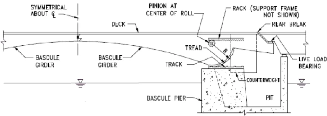
The Underneath Counterweight Strauss type operation is showned in the figure 2.15. The principle of this type is the same as the described above for the Overhead Counterweight, but with the counterweight and link located underneath the road level. This is normally used when exists ample clearance between high water level and road level.
One feature that has been responsible for many discussions throughout the years is the existence of the link connecting the counterweight with the trunnion tower. Some says that for a small angle of opening the friction in the counterweight trunnion bearings may not permit the rotation of the support in order to C-E remains vertical. During the opening of the bridge the angle increases and the moment applied to C would increase as well, being that if exceedes the bearing frition moment the counterweight would swing without any restriction, which could cause the inability to control the moving leaf. (Berger, Healy, & Tilley, 2015)
Fig. 2.15 – Strauss underneath Counterweight (Berger, Healy, & Tilley, 2015)
4) Other Types of Bascule Bridges
During the many years, other types of bascule bridges were developed. Some of them were successfully introduced but some others were easily put aside in favor of the most common type’s descridbed above:
Belidor Balance beam Roller Bearing Brown Page Semi-lift Dutch
It is demonstrated in Table 2.1 the main features of the usual types described before.
Table 2.1 – Summary of features of bascule bridge types
Type of bascule bridge Advantages Issues
Rolling
Scherzer
- Provides large angle of openings
- Allows for shorter span lengths
- Allows for smaller counterweights, resulting in smaller piers
- Tends to move transversely during operation
- Requires special detailing of the track
- Initial alignment challenges - Requires additional machinery
(i.e. tail locks)
- Operating machinery mounted to the movable span
Rall
- Provides large angle of openings
- Allows for shorter span lengths
- Rollers can be removed for repairs when the bridge is closed (relieved of all load)
- Higher level of friction between the elements
- Weight taken by line contacts between the rollers and their tracks Simple Trunnion or ‘Chicago’ - No channel obstruction - No visual impact - Trunnion on fixed axis - Provides reliable
operation
- Span opens and closes same each time
- Requires longer span, deeper pier compared to rolling lift or other counterweight types - Requires special counterweight
detailing to maximize angle of opening and avoid interference with trunnion
- Transverse horizontal axis trunnion supports
Strauss or Multiple trunnion Heel-Trunnion - Small substructure - Allows for low profiles
without counterweight pit - Pivot/Trunnion closer to
navigation channel, providing same channel as simple trunnion with shorter leaf
- Stress reversals at rocking truss and counterweight link
- Overstressed pins and rocking truss
Overhead Counterweight
- Small substructure - Allows for low profiles
without pit
- Inadequate counterweight tower on some versions
Underneath Counterweight
- Good architectural appearance
- Excessive friction in the counterweight linkage and trunnion bearings induces repetitive bending moment in the counterweight hangers –
especially at small angle of openings
- Adequate height to allow the counterweights to swing
2.2.2.SWING BRIDGES
Swing bridges are those who can provide a navigation channel by rotating about a vertical axis by a horizontal plane, normaly 90 degrees. This movement is possible by pivoting on a central pier through bearings connecting the deck and this pier, making it a pivot point. The movable span of a swing bridge - also called draw – is designated of bobtailed or unequal-armed when the arms are not of equal length and designated of symmetrical or equal-armed when the arms are of equal length (with the pivot point in the midle of the draw).
These, comparatively with other type of movable bridges, like bascule and vertical lift, are not lifted, so the lift mechanism is not equilibrated by gravity, being required a device to stop the span at the right position, i.e in the direction of the channel traffic. (Koglin, 2003)
Operation - When in open position ther is no limit on air draught and the visual impact is considered minimum. The wind load is not as severe as other types of bridges, so is require less installed power and therefore more high efficiency.
Superstructure - Depending on the length of the crossing channel, swing bridges can be built with one or two arms so they can be used for all span lengths - 10 until 300m. The tail or backspan are typically 30 – 40% of the main span, so it is needed a longer superstructure comparing with other types of movable bridges.
The principle characteristic noticed on these bridges is the necessity of having a big area to store the moving span when in open position. In the case of a two arms swing bridge, this has be sited in the midle of the navigation channel, thus reducing the length for navigation and turning the maintenance task more
inaccessible and difficult. As normally, the superstructure and substructure are kept above the river water level, so a collision protection is needed along the full length of the superstructure.
Although there is no need for counterweights in the design of most swing bridges, it is required a wedging system, which is mechanically more complicated than other types, and thus potentially more labour intensive in maintenance.
Swing bridges are categorised according to their type of bearing - centre bearing, rim bearing, combined-bearing, slewing-bearing and pontoon-supported swing bridges. The most common types and described here are the first two.
Fig. 2.16 - Centre bearing swing bridge (Ryall, Parke, & Harding, 2000)
Fig. 2.17 - Rim bearing swing bridge (Ryall, Parke, & Harding, 2000)
On centre bearing swing bridges, when the bridge is in operation, all the dead load of the moving span is supported by the pivot bearing, i.e the span rotates on a single bearing support. The rotation of this type can be carried out by means of mechanical or hydraulic machinery.
Fig. 2.18 – (a) Mechanical centre bearing (b) Mechanical rim bearing (Birnstiel, Bowden, & Foerster, 2015)
On rim bearing swing bridges, when the bridge is in operation, all the dead load of the moving span is supported by a serie of rollers on a circular track. The diameter of this circular track is usually around the same tranverse size as the outer swing span. This type is normaly used for long span or heavily loaded swing bridges.
2.2.3.VERTICAL BRIDGES
Vertical lift bridges are those capable of raising their deck vertically, keeping it horizontal (parallel to the water line), thanks to two or four side towers on each side of the bay in question. The lifting process is relatively simple, by means of a roller mechanism in the towers that go through cables, fixed to the span, which pass over the towers and are fixed to counterweights. These cables, through mechanical machines, can move upwards and consequently the counterweights downwards. The counterweights can be sited at the top of the towers externally or internally and ensure a balance of the system and minimize the amount of power require for the bridge lift process. This process is equivalent to a lift mechanism of a building.
This type of bridges has certain advantages over other bridges:
Simplicity - The usual bridge lift does not have much effort in its design and construction, in relation to other bridges. The complicated details are few and/or not complex.
Length of Span - These bridges can have longer spans and be more economically constructed than other types of movable bridges.
Lifting - The vertical lift bridge has the ability to be partially or totally raised, depending on the type of vessels, reducing the time of crossing of the navigable channel. The time required to the complete lift operation, i.e. opening of the bridge plus boat passage and lowering of the bridge is less than for the swing bridges. This occurs because there is no channel/river obstruction time in the operation.
Construction costs - Larger spans have less construction costs in this type of bridge.
Colision with vessels - In case of a collision with the bridge, at the time of elevation, it would be very likely to suffer damage only through the masts or chimneys of the boats and the pilot’s tower. While, in the case of bascule and rotating bridges, the span would be smashed. Professionals say that the time for reconstruction would be shorter than for other bridges.
Interchangeable spans - In case of a bridge with several spans and in which the river is quite likely to change its water flow, this type of bridge can be constructed in such a way to be possible the movement of its towers, counterweights and machinery from one bay to another. This is possible because the spans are all constructed equaly.
Traffic - The weight of the counterweights must be equal to that of the deck, so heavier materials can be used in the deck, therefore heavier traffic can be used.
Despite the many advantages that this bridge entails, the biggest disadvantage in relation to other bridges is the restriction in height. As an elevation of the deck is made, it is suspended above the channel, which causes air draught limit.
Vertical lift bridges are normally labelled by the arrangement of the drive machinery:
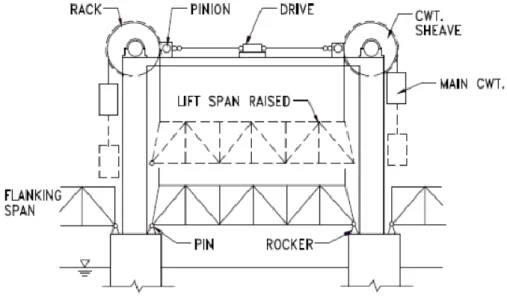
Tower drive vertical lift
The tower lift system uses machinery located at each tower to raise the span. In this case, in addition to the normal lifting mechanism, it is often needed to implement differential height control equipment of the tray, as each equipment operates individually in each end, allowing the tray to be tilted. The equipment is located at the top or bottom of the towers, being the force required for the elevation transmitted by the cables to the counterweights usually by winches. (Berger, Healy, & Tilley, 2015)
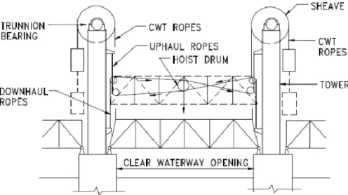
Span drive vertical lift
Span drive vertical lift are categorised by having the drive machinery loacted on the span, normally at mid-span. The counterweights balance the weight of the span, transmitted by ropes, however for large span bridges this balance is difficult due to the difference in weights. Therefore, an auxiliary counterbalance system is needed to mitigate this difference. (Berger, Healy, & Tilley, 2015)
Fig. 2.20 - Span drive vertical lift system (not to scale) (Berger, Healy, & Tilley, 2015)
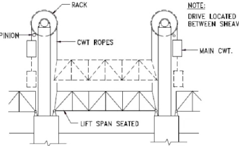
Connected tower drive vertical lift
These type of bridges are most suitable for small span bridges, so there is no need for an auxiliary counterweights system. The machinery is mounted at the top of the span, as can be seen in the figure below, but its positioning may vary depending on bridges.
The mechanism works by means of a force received by the drive, which makes the pinions to rotate engaging the racks attached to the sheaves, causing them to rotate as well. These then transmit by friction to the ropes of the counterweights, thereby raising and lowering the span.
This type of mechanism has the advantage that there is no inclination of the tray due to the position and connectivity of the different equipments. In spite of this, with time it is possible some misalignment or stretching of the ropes, causing inclinations to occur, being necessary for that reason a maintenance of the equipment. (Berger, Healy, & Tilley, 2015)
Fig. 2.21 - Connected tower drive vertical lift system (not to scale) (Berger, Healy, & Tilley, 2015)
Pit drive vertical lift
Characterized by the fact that the lifting mechanism is not visible when the bridge is in low position, it is used when there are aesthetic restrictions and for low lifting heights. The towers supports are not required and the ascent is driven by hydraulic cylinders installed in wells, located inside the pillars. These are normally below the water level of the channel / river. This mechanism is achieved through lifting posts (see figure 2.22), i.e. fixed legs inside the pillars that extend and collect. These posts, guide the movable span during the movement and resist the horizontal forces applied to the span when it is in opened position. The number of lifting posts depends on the width of the span.
This type of bridges are also able to withstand counterweights and sheaves to decrease the weight to be raised, however these features are uncommon because the use of mechanical cylinders with electric motors provides higher lifting power. (Berger, Healy, & Tilley, 2015)
3
MOVABLE BRIDGE
CONCEPTUAL DESIGN
3.1. GENERAL
The design process of a bridge can be divided into three major stages: conceptual design, preliminary design and detailed design. The lifecycle comprises six main topics as shown in Figure 3.1.
Fig. 3.1 - Main bridge lifecycle
Conceptual design
The concept design starts with the Brief of the owner/client – highways agency or regional or local authority – where the location of the bridge and main objective are presented. It is at this stage that the understanding of surrounding features, and possible constraints is critical. Aspects such as economic, social and cultural impact are particularly relevant and have to be taken into account.
The overall process goes on with the set-up of various road alignments from the highways team alongside possible bridge configurations from the structures/bridge team. For the bridge itself, this is the stage where certain features are considered, such as: number of spans; type of articulation; load path; and thus the type of bridge – truss, arch, beam and slab, box girder, etc. Other disciplines teams also take part in the process of the initial selection such as: environmental, transport planning and geotechnical.
After high level discussions between all disciplines and the client, the number of initial options – ranking usually from 10 to 20 high level options – is typically narrowed to 2 - 3 road alignments. Following this, different types of bridges are proposed accounting for the aforementioned features and constraints, where a number of 3 to 6 concept options is presented to the authorities responsible for the decision making development. Conceptual design Preliminary design Detailed