Design of a Body Sensor Network
Embedded in Textiles for Biomedical
Applications
Fardin Derogarian Miyandoab
A dissertation submitted to the Faculty of Engineering of the University of Porto in accordance with the requirements for the degree of Doctor in Telecommunications
Supervisor: Prof. João Canas Ferreira Co-Supervisor: Prof. Vítor Grade Tavares
for Biomedical Applications
Fardin Derogarian Miyandoab
A dissertation submitted to the Faculty of Engineering of the University
of Porto in accordance with the requirements for the degree of Doctor in
Telecommunications
Jury:
Prof. José Alfredo Ribeiro da Silva Matos Prof. Maria Helena da Costa Matos Sarmento Prof. Fernando José da Silva Velez
Prof. Rui Luís Andrade Aguiar
Prof. Rui Manuel Escadas Ramos Martins Prof. José Alberto Peixoto da Silva Prof. João Paulo de Castro Canas Ferreira
Body Sensor Networks (BSNs) or Body Area Networks (BANs) refer to a subcategory of sensor networks mainly used for measuring or monitoring vital body parameters with-out affecting the lifestyle of human beings. These systems can be used at care centers or at home by patients or even healthy people who want to improve or monitor his/her health conditions. It is expected that in the coming years, BANs will help bring about revolutionary changes in health care systems and applications.
A BAN consists of wearable or implantable sensors or computing devices, and a com-munication network for data collection. Usually, an on-body system is responsible for collecting data from sensors via an intra-network and send them to a computer or PDA via a wireless link. According to the application and design parameters, the intra-network can be wired, wireless or even use the human body as communication medium.
The purpose of the work described in this dissertation is to design and evaluate a new wearable BAN to support measuring human locomotion parameters in the most practical, comfortable and non-invasive way. The entire communication infrastructure, including hardware, software and protocols, has been designed for this purpose. Although the de-sign of the de-signal acquisition modules, driver software and data processing programs are beyond the scope of the present work, the designed communication system was embedded together with those facilities and tested in real data-acquisition experiments. This disserta-tion then focus on the networking component, in its different levels. The proposed system can also be used in many other BAN applications, especially those including a large num-ber of sensors in BAN scale, embedded in textile and with high data-rate communication demands. The overall system includes an on-body central processing module connected to a computer via a wireless link and a wearable network sensor. Due to the fixed location of the sensors and the possibility of using conductive yarns in textiles, a wired network has been considered for the wearable components. Employing conductive yarns instead of using wireless links in the wearable unit provides a more reliable communication, higher data rates and throughput, and less power consumption. The wearable unit is composed of two types of circuits including sensor nodes and a base station, all connected to each other with conductive yarns forming a mesh topology with the base node at the center. In comparison with traditional serial or star topologies, a mesh connection is more reliable, provides higher data-rate communication and supports significantly more sensors. From the standpoint of the network, each sensor node is a four port router capable of hand-ing over packets from destination nodes to the base station. For experimental evaluation, all nodes were connected to existing data acquisition boards capable of acquiring elec-tromyography (EMG) signals (electrical signals from the skin) and kinetic information (using accelerometers and gyroscopes).
paths with the base node at the center. The physical and MAC layers have been imple-mented on a low-power FPGA (Actel IGLOO AGLN125). The second prototype was designed to improve the performance of the system based on observed limitations when using packet switching in the first prototype. The end-to-end communication in the second prototype uses a hybrid circuit and packet switching; packet delivery from sensor nodes to the base station uses hybrid switching, while in the reverse direction, or between sen-sor nodes, packet switching is used. This hybrid switching scheme significantly improves system performance in terms of end-to-end delay, throughput and power consumption. The communication module of the second prototype has been implemented on an inte-grated circuit (IC) using a 4-metal, 0.35 µm CMOS technology. The maximum data rate of the system is 35 Mbps while supporting tens of sensors, which is much more than cur-rent BAN applications need. The IC also implements a highly precise, sub-microsecond one-way time synchronization protocol, which is used for timestamping the acquired data. The suitability of the proposed system for utilization in real applications has been demon-strated experimentally with a test setup for collecting data from movements of the lower limbs.
The main contributions of the present dissertation are:
• The SRMCF reactive routing protocol for both wired and wireless networks. The protocol has been implemented on the designed wearable system and also on TelosB wireless motes.
• Hardware prototypes of sensor nodes (excluding acquisition circuitry), base sta-tion and central processing module with physical and MAC layers implemented on FPGA. The prototypes are multi-task devices that support asynchronous communi-cation and concurrent send/receive operations.
• Hardware implementation of a hybrid circuit and packet switching mechanism for end-to-end communication.
• A low-overhead, time-division multiplexing MAC protocol for the circuit switching mechanism implemented in the proposed BAN.
• A very small circuit implementing a fully-digital clock and data recovery mecha-nism.
• A one-way, sub-microsecond, highly precise time synchronization protocol and its circuit implementation.
• A low-power IC for use in the second hardware prototype of sensor nodes and base station. The IC implements a transmitter, a receiver, the network layers up to the routing layer, an SPI port, support for hybrid switching, a 2 kB RAM, and is able to perform time synchronization and communicate at data rates up to 35 Mbps.
As designações Body Sensor Networks (BSN) ou Body Area Networks (BAN) referem-se a uma subcategoria de redes de referem-sensores que é usada principalmente para a medição ou monitorização de parâmetros vitais do corpo sem afetar o estilo de vida do ser humano. Estes sistemas podem ser usados em hospitais ou em casa pelos pacientes, ou mesmo por pessoas saudáveis que querem melhorar ou controlar as suas condições de saúde. Espera-se que, nos próximos anos, as BANs tragam mudanças revolucionárias nos sistemas de saúde e aplicações.
Uma rede BAN consiste em alguns sensores ou elementos de processamento vestíveis ou implantáveis e numa rede para recolha de dados. Normalmente, um sistema vestível é responsável por recolher dados dos sensores através de uma rede interna e enviá-los para um computador ou PDA através de uma ligação sem-fios. De acordo com os parâmetros da aplicação e de projeto, a rede interna pode ser construída com fios, sem fios ou mesmo utilizando o corpo humano como meio de comunicação.
O objetivo deste trabalho de dissertação é a conceção e avaliação de um novo sis-tema vestível para medir parâmetros de locomoção humana, da maneira mais prática, confortável e não-invasiva. Toda a infraestrutura de comunicação, incluindo software, hardwaree protocolos, pois foi projetada para este fim. Embora quer o projeto dos módu-los de aquisição de sinal e respetivos controladores quer o desenvlvimento dos programas de tratamento de dados estejam fora do âmbito deste trabalho, o sistema de comunicações desenvolvido foi integrado com estes componentes e testado em experiências de aquisição de dados reais. Esta dissertação foca-se na componente de rede, nos seus diferentes níveis. Os resultados alcançados e o sistema projetado também podem ser usados em muitas aplicações BAN, especialmente aplicações que incluem um grande número de sensores embebidos em têxteis e para comunicações que requerem elevada taxa de transferência de dados. O sistema inclui um módulo de processamento central ligado a um computador através de uma ligação sem fios e uma rede de sensores vestível. Devido à localização fixa dos sensores e possibilidade de utilização de fios condutores têxteis, foi considerada uma rede com fios para interligar os sensores. Empregando fios condutores em vez de usar as ligações sem fios possibilita, uma maior taxa de transferência de dados, maior rendimento e menor consumo de energia. A parte vestível é composta por dois tipos de circuitos, nós sensores (SNS) e um estação-base (BS), todos interligados com os fios condutores que formam uma topologia em malha com o BS no centro. Em comparação com as topologias tradicionais, série ou estrela, uma ligação em malha é mais confiável, fornece comunicação com maior taxa de transferência de dados e suporta significativa-mente mais sensores. Do ponto de vista da rede, cada nó tem 4 portos de comunicação e atua como um encaminhador de pacotes para a estaao-base. Todos os nós sensores foram equipados com um circuito de aquisição de sinais electromiográficos (EMG) e também
em comutação de pacotes. O protocolo de roteamento SRMCF foi projetado para estab-elecer spanning trees de todos os caminhos com um custo de encaminhamento mínimo para a estação-base. As camadas físicas e MAC foram implementadas numa FPGA de baixo consumo (Actel IGLOO AGLN125). O segundo protótipo melhora o desempenho do sistema eliminando as desvantagens, observadas no primeiro protótipo, associadas à utilização de comutação de pacotes. Neste protótipo a comunicação extremo-a-extremo é estabelecida com base em comutação híbrida combinando comutação de pacotes e de cir-cuitos: a transmissão de pacotes na direção SNs para BS emprega comutação híbrida; na direção reversa ou entre nós usa comutação de pacotes. Esta comutação híbrida melhora significativamente o desempenho do sistema em termos de atraso de extremo-a-extremo, débito e consumo de energia. O módulo de comunicação do segundo protótipo foi imple-mentada num circuito integrado fabricado em tecnologia CMOS de 0,35 µm com quatro níveis de metal. A taxa máxima de transmissão de dados do sistema é de 35 Mbps com dezenas de sensores, o que é muito maior do que as necessidades das aplicações Body Area Network (BAN) atuais. O Application-specific Integrated Circuit (ASIC) inclui também um protocolo de sincronização sub-microssegundo unidirecional de alta precisão, que permite etiquetar os dados adquiridos com informação temporal precisa. A capaci-dade do sistema proposto ser usado em aplicações reais foi provada experimentalmente na recolha de dados dos membros inferiores em movimento.
As principais contribuições e novidades da dissertação são:
• O protocolo de roteamento SRMCF reativo para ambas as redes com e sem fio. O protocolo foi implementado num sistema vestível projetado e também sobre as motes sem fio TelosB.
• Protótipos em hardware dos nós, da estação-base e do módulo de processamento central com as camadas física e MAC implementadas em FPGA. Os protótipos são dispositivos multi-tarefa capazes de comunicação assíncrona e operações de receção/transmissão concorrentes.
• Implementação em hardware de um mecanismo híbrido comunicação por comu-tação de pacotes e comucomu-tação de circuitos.
• Um protocolo de baixo custo para multiplexagem no tempo ao nível MAC imple-mentado para a rede BAN proposta.
• Um circuito digital muito pequeno para recuperação de relógio e dados (CDR). • Um protocolo de sincronização unidirecional de elevada precisão (sub
microse-gundo) e a respetiva implementação em hardware.
• Um circuito integrado de aplicação específica (ASIC) para uso no segundo pro-tótipo dos nós sensores e da estação-base. O ASIC inclui recetor, transmissor, todos os níveis de rede até ao nível de roteamento, um porto SPI, suporte para comu-tação híbrida de pacotes e circuitos, e uma memória RAM de 2 kB, sendo capaz de sincronização temporal precisa e comunicação a taxas de dados até 35 Mbps. Todos os projetos desenvolvidos foram analisados teoricamente e testados experimen-talmente.
I wish to thank all the people who have helped me throughout the years that I needed to complete the dissertation.
First of all I would like to thank my supervisor Prof. João Canas Ferreira. This dissertation would not have been possible without the support of his. I appreciate his guidance and right suggestions at the right time.
I would like to thank my co-supervisor Prof. Vítor Grade Tavares for his great com-ments, the thesis has greatly benefited from them.
I also would like to thank Prof. José Machado da Silva for his support and valuable suggestions.
A huge thanks goes to my family for their support and encourage. This dissertation is dedicated to my family, especially to my parents.
I would like to thank my friend Reza who has suggested me MAP-Tele telecommuni-cation doctoral program.
I would like to thank Ruben for his remarkable effort to use the designed system for data acquisition.
I would like to thank my colleagues and friends, Nassim, Porkodi, Simona, Moham-mad, Zhaleh, Cristina, Ganga, João, and Bruno.
Finally I would like to thank Portuguese funding organization FCT, INESC and FEUP.
1 Introduction 1
1.1 Body Area Networks . . . 2
1.2 Wearable Health Systems . . . 4
1.3 Research Motivation . . . 5
1.3.1 The ProLimb Project . . . 6
1.3.2 Research Goals . . . 7
1.4 Research Contributions . . . 8
1.5 Dissertation Outline . . . 10
2 Background and State of the Art 13 2.1 Initial Work on Body Area Networks . . . 13
2.2 Communication Methods . . . 14
2.2.1 Wireless Communication . . . 14
2.2.2 Wired Communication . . . 15
2.2.3 Human Body Communication . . . 16
2.3 Communication Architecture of Body Area Networks . . . 16
2.4 Types of BAN Nodes . . . 18
2.5 Sensors . . . 19
2.6 Related Work in Wearable Networks . . . 20
2.7 BAN Operations by Network Layers . . . 22
2.7.1 Physical Layer . . . 22
2.7.2 MAC Layer . . . 25
2.7.3 Network Layer . . . 28
2.7.4 Cross-Layer protocols . . . 30
2.8 Clock and Data Recovery . . . 31
2.8.1 Related Work . . . 32
2.9 Time Synchronization . . . 33
2.9.1 Related Work . . . 34
2.10 Conclusion . . . 36
3 A Routing Protocol for Sensor Networks 37 3.1 Overview of the SRMCF Protocol . . . 37
3.1.1 Supported Message Types . . . 38
3.1.2 Network Setup . . . 40
3.1.3 Link and Node Failure Recovery . . . 41
3.2 Modeling and Implementation of the SRMCF Protocol . . . 43
3.2.2 Protocol Implementation Details . . . 46
3.3 Protocol Analysis . . . 50
3.3.1 Packet Count . . . 50
3.3.2 Packet Header Length . . . 53
3.3.3 Routing Table Size . . . 53
3.4 Simulation and Experimental Results . . . 54
3.4.1 Simulation Parameters . . . 54
3.4.2 Setup time . . . 55
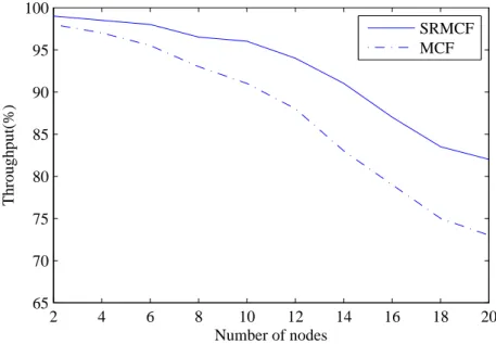
3.4.3 Network Throughput and Packet Delivery . . . 57
3.4.4 Energy Consumption . . . 60
3.4.5 Failure Recovery . . . 61
3.4.6 Routing Table and Packet Header Size . . . 62
3.4.7 Throughput in Wired Networks . . . 65
3.5 Conclusion . . . 67
4 Wearable System Architecture 69 4.1 Design of the Network . . . 69
4.1.1 Characterization of the Conductive Yarns . . . 70
4.1.2 Intra network . . . 71
4.1.3 Hop-Count Bounds and Number of Ports per Node . . . 74
4.2 Design Considerations for Each Network Layer . . . 76
4.2.1 Physical Layer . . . 76
4.2.2 MAC layer . . . 80
4.2.3 Network Layer . . . 85
4.2.4 Middleware and Application Layers . . . 86
4.3 First Prototype . . . 87
4.3.1 Sensors, Base Station and Central Processing Module circuits . . 87
4.3.2 FPGA-base Implementation of the Physical and MAC layers . . . 88
4.4 Experimental Results . . . 96
4.4.1 Communication in the MAC layer . . . 96
4.4.2 Routing . . . 99
4.4.3 Power consumption . . . 100
4.4.4 Data acquisition examples . . . 102
4.4.5 Network of Sensors on Textile . . . 105
4.5 Conclusion . . . 109
5 Synchronization Protocols 111 5.1 Clock Synchronization . . . 111
5.1.1 Motivation . . . 112
5.1.2 Synchronization Method . . . 113
5.1.3 The Synchronization Circuit . . . 119
5.1.4 Experimental Results . . . 123
5.1.5 Conclusion . . . 132
5.2 Time Synchronization . . . 132
5.2.1 Motivation . . . 132
5.2.2 Description of the Synchronization Protocol . . . 133
5.2.4 The Synchronization Circuit . . . 144
5.2.5 Experimental Results . . . 150
5.2.6 Conclusion . . . 157
6 Architecture and Implementation of a Communications ASIC 159 6.1 Bufferless Communication and Circuit Switching . . . 159
6.1.1 A TDM MAC Protocol Based on Circuit Switching . . . 160
6.1.2 Circuit Path Construction . . . 162
6.1.3 Scheduling Node Transmissions . . . 163
6.1.4 End-to-end delay . . . 167
6.1.5 Bit Error Probability for Circuit Switching . . . 168
6.1.6 Synchronization of Time Slots . . . 169
6.1.7 Hybrid switching . . . 169
6.2 Integrated Circuit for Sensor Node Communication . . . 170
6.2.1 Router and Buffer Module . . . 171
6.2.2 Transmitter Module . . . 173
6.2.3 Receiver Module . . . 174
6.2.4 Signal Detector . . . 174
6.2.5 Circuit Switching Module . . . 177
6.2.6 Time Synchronization Module . . . 180
6.2.7 Clocking . . . 180
6.3 ASIC Implementation Flow . . . 182
6.4 Experimental Results . . . 184
6.4.1 Routing Operations . . . 186
6.4.2 Power consumption . . . 189
6.4.3 Concurrent Multitasking . . . 191
6.4.4 Channel Utilization . . . 191
6.4.5 Circuit Switching on Wearable Network . . . 193
6.5 Conclusion . . . 194
7 Conclusion and Future Work 197 7.1 Conclusion . . . 197
7.2 Future Work . . . 198
7.3 Publications . . . 199
A Schematics for Circuits 201
B ASIC Testbench Examples 207
C Acquisition of Locomotion Data 211
1.1 Lab setup for EMG . . . 6
2.1 Communication architecture of BAN. . . 17
2.2 Typical architecture of a biomedical sensor. . . 20
2.3 Conductive yarns . . . 24
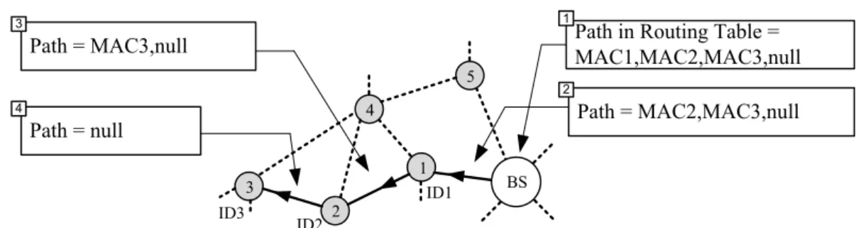
3.1 Value of path and length fields at different nodes. . . 39
3.2 Adjusting the path from SN3 to BS . . . 41
3.3 Failure recovery. . . 42
3.4 Network setup . . . 43
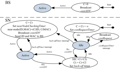
3.5 Routing table creation in the BS with collaboration of sensor nodes. . . . 44
3.6 Routing operation of sensor nodes. . . 45
3.7 Failure recovery. . . 45
3.8 Building and running simulation in OMNeT++. . . 47
3.9 Base Station (BS) and Sensor Nodes (SNs) nodes in OMNeT++. . . 48
3.10 The architecture of Contiki OS. . . 50
3.11 A network topology with maximum average hop count . . . 52
3.12 The photograph of the TelosB. . . 55
3.13 Networks with different arrangement of motes. . . 56
3.14 Network setup time for SRMCF and MCF. . . 58
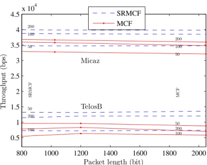
3.15 Throughput of the network. . . 59
3.16 Simulation and experimental results for packet delivery. . . 59
3.17 Energy consumption of network with 50 nodes (simulated). . . 60
3.18 Number of the active nodes. . . 61
3.19 Energy consumption of query processing . . . 63
3.20 Average initial packet header size. . . 64
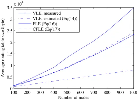
3.21 Average size of routing tables built using three different methods. . . 65
3.23 Ratio of routed packets to generated packets . . . 66
4.1 General architecture of the system. . . 70
4.2 Serial bus and mesh Interconnection modes. . . 72
4.3 Frequency response of the serial bus network. . . 73
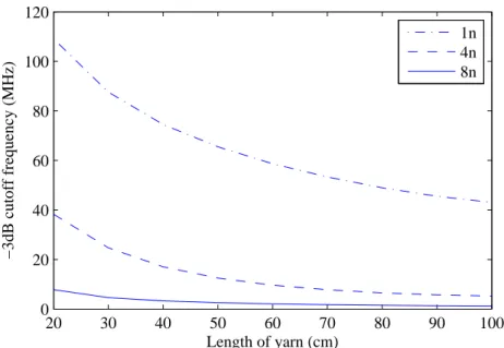
4.4 -3dB cut off frequency as a function of the length of conductive yarns. . . 73
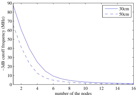
4.5 -3dB cut-off frequency in terms of node number. . . 74
4.6 A random generated network. . . 75
4.7 Network layers. . . 76
4.8 Connection between the nodes in physical layer. . . 77
4.10 Received baseband signal affect by white noise. . . 78
4.11 Sampling of received signal. . . 79
4.12 Probability distribution of signal levels. . . 79
4.13 RTS/CTS MAC protocol. . . 81
4.14 MAC frame: a) MAC control frame; b) MAC data frame. . . 81
4.15 Messages at the ports of BS. . . 83
4.16 Payload format. . . 86
4.17 Data format in application layer. . . 87
4.18 Overall organization of the SNs and BS. . . 88
4.19 Block diagram of CPM. . . 89
4.20 Communication module implemented on a FPGA. . . 90
4.21 Interface for accessing the registers of the internal modules. . . 90
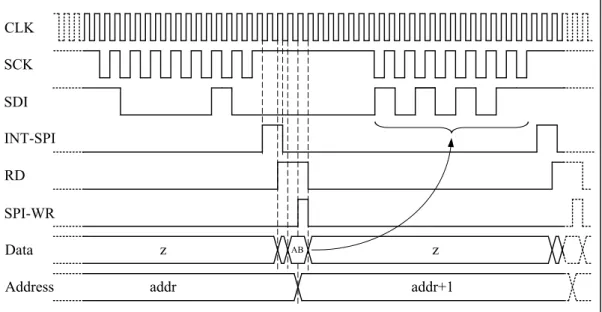
4.22 Communication format via SPI port. . . 91
4.23 Reading a register value and sending it directly to the microcontroller. . . 92
4.24 Microcontroller writes a value to a register. . . 92
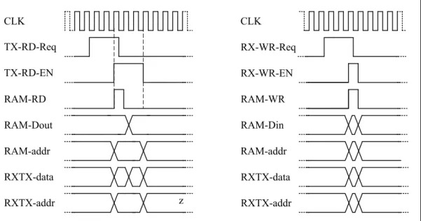
4.25 Timing diagram of reading and writing in data bus. . . 93
4.26 Block diagram of Data Buffer module. . . 93
4.27 Buffer segment format. . . 94
4.28 Signal detector module. . . 94
4.29 Block diagram of the transmitter module. . . 95
4.30 Block diagram of the receiver module. . . 96
4.31 Picture of the prototype; a) SN and BS, b) CPM . . . 97
4.32 Encapsulated data packet in MAC layer. . . 98
4.33 Signals over the line. . . 98
4.34 Node-to-node throughput as a function of packet length. . . 99
4.35 A network contains three SNs and BS. . . 100
4.36 Routed packet at different points of the network . . . 101
4.37 Data transmission from SN3 to BS. . . 101
4.38 Power consumption in terms of data rate (VCC = 1.5 V). . . 101
4.39 a) Setup for sEMG, b) Sensor node placement . . . 102
4.40 Acquired electromyographic and inertial signals . . . 103
4.41 Example of data acquired in real time from the gyroscopes . . . 104
4.42 A network of SNs embedded in textile. . . 105
4.43 Average number of the packets in buffers with 20.8 kbps traffic per node . 106 4.44 Packet loss probability with 20.8 kbps traffic per node . . . 106
4.45 Average number of the packets in buffers with 640 kbps traffic per node . 107 4.46 Packet loss probability with 640 kbps traffic per node . . . 107
4.47 Average end-to-end delay. . . 108
4.48 Throughput of the network in terms of the packet length. . . 108
5.1 A mesh-based body area network. . . 112
5.2 NRZI signal S(t) generated from ms(t). . . 114
5.3 Receiver clocks and incoming signal. . . 116
5.4 Boundaries of sampling range in the presence of jitter. . . 117
5.5 ∆ϕ(t) for m = 2 and m = 3 with ∆ f < 0. . . 118
5.6 Block diagram of the circuit. . . 120
5.8 Ca(t), Cb(t) and C1(t) signals. . . 121
5.9 Shifting the negative pulses of Cr(t) to the left. . . 122
5.10 Shifting the negative pulses Cr(t) to the right. . . 123
5.11 Combined circuit for synchronization and NRZI decoding. . . 124
5.12 Signals captured using 5 s persistence. . . 125
5.13 Signals at the receiver when no local clock adjustment is needed. . . 126
5.14 Correction of receiver clock Cr(t) when Ts> Tr. . . 126
5.15 Correction of receiver clock Cr(t) when Ts< Tr. . . 127
5.16 Initiating generation of Cr(t) after exiting from sleep mode. . . 128
5.17 Eye diagram and synchronized clock signal Cr(t). . . 128
5.18 Measured BER and safe sampling range . . . 129
5.19 A network of sensors with the BS node acting as clock time reference. . . 134
5.20 Format of the timing information message. . . 135
5.21 Timing diagram: a) PTP protocol, b) proposed protocol . . . 137
5.22 Clocks and signals in sender and receiver nodes . . . 139
5.23 Average skew hCShi as a function of hop count h. . . 142
5.24 Sequence of MAC messages for clock synchronization . . . 144
5.25 Sending the Request message and receiving Sync messages (slave node). . 145
5.26 Replying to a Request message with a Sync message (in master node). . . 145
5.27 Block diagram of the circuit. . . 146
5.28 Operation of Control module. . . 147
5.29 Counters: a) TC-Counter, b) TS-counter . . . 148
5.30 Configuration of Sender Receiver to send a request. . . 149
5.31 Configuration of Sender-Receiver for reply to a request . . . 150
5.32 Configuration of Sender Receiver to receive timing message. . . 150
5.33 Physical layer signals during timing message exchange. . . 151
5.34 Simulation showing synchronization of Clk-sync signal and TS counter. . 152
5.35 Measured one-hop clock skew for Offset =0x002E, 0x002F and 0x0030. . 153
5.36 Measured multi-hop clock skew with Offset = 0x002F. . . 153
5.37 Comparison between the measured and calculated values. . . 154
5.38 The circuit current consumption for fsyncup to 5 MHz . . . 154
5.39 One-hop skew after consecutive timing message failures. . . 155
5.40 Average clock skew after disconnection of the line . . . 156
5.41 Clock skew for update interval of 1.5 s and 5 s, Clk-sync = 1 kHz. . . 157
6.1 A random generated network with 3 subset of the nodes . . . 162
6.2 Routing a packet from n4to BS by using circuit switching. . . 163
6.3 Time slot assignment for nodes n1and n12. . . 164
6.4 Constructing paths for nodes n2and n4. . . 165
6.5 Time slots and the alignment error due to tC. . . 169
6.6 Network integrated circuit. . . 171
6.7 Flowchart describing the routing process . . . 173
6.8 The three different types of RTS messages . . . 175
6.9 Signal detector module for tracking line activity. . . 176
6.10 RTS detector module . . . 176
6.11 Organization of the circuit switching module . . . 177
6.13 Example of packet delivery over a circuit . . . 178
6.14 a) Organization of the Clock module, b) gated clock. . . 181
6.15 Design flow of the circuit for both ASIC and FPGA. . . 182
6.16 IC Layout; 4 metal CMOS 0.35 µm . . . 183
6.17 Example of a testbench with four SNs and BS. . . 184
6.18 Photo of second sensor node prototype used for evaluating the ASIC. . . . 185
6.19 SOIC20 package and photograph of the integrated circuit. . . 185
6.20 Delivering a packet generated by SN3 to BS only by packet switching. . . 186
6.21 An example of pure circuit switching. . . 187
6.22 Details of message exchange to establish the circuit path . . . 188
6.23 Status of the communication ports of each SN during circuit switching. . 188
6.24 An example of hybrid switching. . . 189
6.25 Measured ASIC supply current . . . 190
6.26 The measured power consumption in terms of data rate (VCC = 3.3 V). . 190
6.27 The measured power consumption in terms of data rate. . . 191
6.28 Network used for evaluation of communication multitasking. . . 191
6.29 Signals on the data lines of SN2. . . 192
6.30 Channel utilization in MAC layer. . . 192
6.31 End-to-end delay as a function of packet length for two data rates. . . 194
6.32 Throughput of network for unoptimized time slot duration . . . 195
6.33 Throughput of network for optimized time slot duration. . . 195
A.1 Schematic of SN and BS. . . 202
A.2 Schematic of the port module. . . 203
A.3 The Central Processing Module (CPM) schematic. . . 204
A.4 Schematic of the second sensor node prototype. . . 206
B.1 A testbench with a BS and four sensor nodes. . . 208
B.2 Configuring the communications ASIC. . . 208
B.3 Loading a packet to a buffer in the ASIC. . . 209
B.4 Sending a packet by circuit switching . . . 210
B.5 Simulation of TC and TS synchronization. . . 210
C.1 E-legging for capturing human locomotion . . . 212
C.2 Interconnection diagram of wearable platform. . . 213
C.3 Interconnection diagram of e-legging. . . 213
C.4 sEMG, acceleration and angular rate signals captured with the SN1. . . . 214
C.5 sEMG, acceleration and angular rate signals captured with the SN3. . . . 214
C.6 sEMG, acceleration and angular rate signals captured with the SN5. . . . 215
C.7 sEMG, acceleration and angular rate signals captured with the SN7. . . . 215
C.8 sEMG signals captured with SN1. . . 216
C.9 sEMG signals captured with SN2. . . 216
C.10 sEMG signals captured with SN3. . . 216
C.11 sEMG signals captured with SN4. . . 216
C.12 sEMG signals captured with SN5. . . 217
C.13 sEMG signals captured with the SN6. . . 217
C.14 sEMG signals captured with the SN7. . . 217
3.1 Contents of the routing table in BS. . . 39
3.2 The cost value before and after failure event . . . 42
3.3 Parameters for the simulation experiments . . . 56
3.4 Parameters of prototype implementation . . . 56
3.5 Experimental setup times for SRMCF and MCF protocols (in seconds) . . 57
3.6 Total energy consumption (in mJ) after running for 100 s (simulation) . . 62
3.7 Total energy consumption (in mJ). . . 62
3.8 Failure recovery time in NW2 . . . 63
4.1 Measured values per unit (@10 MHz). . . 71
4.2 Characteristics of the circuit and its FPGA implementation . . . 97
5.1 The values of jitters. . . 129
5.2 Comparison with other works . . . 131
1-Wire Single-Wire Serial Interface
3G Third Generation of Mobile Telecommunications Technology 4G Fourth Generation of Mobile Telecommunications Technology AC Alternating Current
ACC Accelerometer
ACK Acknowledgement
ADC Analog to Digital
AFH Adaptive Frequency Hopping AGC Automatic Gain Controller
AODV Ad hoc On-Demand Distance Vector Routing Protocol
AP Access Point
ARP Address Resolution Protocol
ASIC Application-specific Integrated Circuit AWGN Additive white Gaussian noise
B-MAC Berkeley-MAC BAN Body Area Network
BCC Body Channel Communication BCU Body Control Unit
BER Bit Error Rate
BS Base Station
BSN Body Sensor Network CAN Controller Area Network CAP Contention Access Period CCA Clear Channel Assessment CDF cumulative density function CDR Clock and Data Recovery CF Conductive-Fabric
CFP Contention Free Period
CMOS Complementary Metal Oxide Semiconductor CPM Central Processing Module
CRC Cyclic Redundancy Check CSMA Carrier Sense Multiple Access
CSMA/CA Carrier Sense Multiple Access with Collision Avoidance CTS Clear to Send
DC Direct Current
DC-PLC Direct Current Power Line Communication DJ Deterministic Jitter
DLL Delay-locked Loop DNA Deoxyribonucleic Acid DSP Digital Signal Processing DSR Dynamic Source Routing ECG Electrocardiography
EDA Electronic Design Automation EEG Electroencephalography
EMG Electromyography
EMI Electromagnetic Interference FIFO First-in First-out
FPGA Field Programmable Gate Arrays FSK Frequency-shift Keying
FSM Finite State Machine
FTSP Flooding Time Synchronization GPRS General Packet Radio Service GPS Global Positioning System
GYR Gyroscope
H-MAC Hybrid MAC
HBC Human Body Communication HCI Human-computer Interface HDL Hardware Description Language I2C Inter-integrated Circuit
IC Integrated Circuit
ICT Information and Communication Technology IDE Integrated Development Environment
IR Impulse Radio
ISM Industrial, Scientific and Medical LAN Local Area Network
LEACH Low Energy Adaptive Clustering Hierarchy LPL Low Power Listening
LQSR Link Quality Source Routing LSB Least Significant bit
MAC Media Access Control MCF Minimum-Cost Forwarding MEMS Micro-electromechanical
MHBC Magnetic Human Body Communication MICS Medical Implant Communication Service
MS Medical Server
MTU Maximum Transmission Unit
NB Narrow Band
NED Network Description NFC Near Field Communication
NoC Network-on-Chip
NRZ non Return to Zero
NRZI non Return to Zero Inverted NTP Network Time Protocol
OS Operation System
OSI Open Systems Interconnection model PAN Personal Area Network
PCB Printed Circuit Board
PD Personal Device
PDA Personal Digital Assistants PDF probability density function
PEGASIS Power-efficient Gathering in Sensor Information Systems
PHR PHY Header
PHS Personal Health System PHY Physical Layer
PLC Power Line Communication PLL Phase-Locked Loop
PMAC Priority Guaranteed MAC
PPDU Physical Layer Protocol Data Unit ppm parts per million
PS Personal Service
PSDU Physical Layer Service Data Unit PTP Precision Time Protocol
QoS Quality of Service
RAM Random Access Memory
RBS Reference Broadcast Synchronization RC Resonance Compensator
RF Radio Frequency
RFID Radio Frequency Identification
RJ Random Jitter
RTL Register Transfer Language RTS Request to Send
RX Receiver
RZ Return to Zero
SAR Specific Absorption Rate
SCK Serial Clock
SD Secure Digital SDI Serial Data Input SDO Serial Data Output
sEMG Surface electromyography SHR Synchronization Header SIPO Serial in Parallel Out
SIR Signal-to-Interference Ratio SMS Short Message Service
SN Sensor Node
SNR Signal to Noise Ratio
SoC System on Chip
SOIC Small Outline Integrated Circuit SPI Serial Peripheral Interface
SR Source Routing
SS Slave Select
TCF Transmission Confirmation Frame TDM Time-division Multiplexing TDMA Time Division Multiple Access
TF Token Frame
TPSN Timing-sync Protocol for Sensor Networks
TX Transmitter
USB Universal Serial Bus UWB Ultra Wide Band
VCO Voltage Controlled Oscillator WBAN Wireless Body Area Network WHS Wearable Health System WiFi Wireless Fidelity
WMTS Wireless Medical Telemetry Services WPN Wearable Personal Network
Introduction
One of the great hopes of mankind is living healthy and overcome illnesses and disabilities. How-ever, in reality, diseases and health problems are inevitable. Besides health problems, the growth of the elderly population is a new challenge that is gradually getting more serious. On the other hand, health care expenditure is already considerable and rises yearly. The impending health crisis has motivated researchers, industrialists, and economists to look for new solutions. Apart from medical treatment methods and medications, biomedical systems and equipments play an impor-tant role in this context. The non-intrusive and ambulatory health monitoring of patient’s vital signs with real time updates of medical records via a network connection may open the way for economical solutions to some of the challenges that health care systems face.
In recent years many promising technological advances in electronics, information technology and communication systems have paved the way to new concepts in health care. For example, telemedicine, eHospital, and ubiquitous health care are enabled by emerging new electronic de-vices and wireless broadband communication technologies. While initially becoming main-stream for portable devices such as tablets and smart phones, wireless communications is evolving to-wards wearable solutions and even implantable solutions are being introduced. These health care devices rely on sensor networks and Body Area Networks (BANs) [YH11, YK12].
The purpose of this dissertation is to design and evaluate a BAN for supporting the measure-ment of human locomotion parameters in the most practical, comfortable and non-invasive way. The work was carried out in the context of the ProLimb project [INE13], but the resulting com-munication system can carry over to many other BAN applications, especially those that include a large number of sensors embedded in textiles and require high data rates (compared to more common BANs). The implementation of the full communication system involved the design of an appropriate communication protocol, of dedicated hardware and of the controlling software, all of which have been designed from scratch for this application. Since the work includes aspects from the electronics, communication and networking fields, this chapter provides a brief general introduction to BANs and wearable systems before discussing the motivation and presenting the main research contributions of this work.
1.1
Body Area Networks
BANs are a category of sensor networks that connect wearable or implantable sensors and com-puting devices. A BAN consists of a set of mobile or fixed and compact intercommunicating sensors, which monitor vital body parameters and movements for medical or non-medical appli-cations [XZ09, YH11, YK12, UHB+12b, SKLF13, DP14]. Each node has enough capability to process and forward information to a base station. In health care, a BAN can be used as the infras-tructure for smart and affordable health care systems that can provide long term health monitoring of patients under natural physiological states without constraining their normal activities. They can be useful as part of diagnostic procedures, in maintenance of chronic conditions, in super-vised recovery from a surgical procedure, and in the detection of emergency events [JMOG05]. The IEEE 802.15 Standard Committee formed a study group (IEEE 802.15.6 SGBAN) to specify a standard for Wireless Body Area Networks (WBANs) [XZ09, KUU10, JM11]. The ability to deploy sensor nodes on the human body creates the opportunity for developing a large number of applications not only in medical health care, but also in several other fields, such as in sports and entertainment, or military and defense.
In sensor-based applications, BANs for both medical and non-medical applications consist of three types of components:
1. In-body and on-body sensors: These include implantable, swallowable and wearable sen-sor nodes with appropriate sensen-sors according to the phenomena to be monitored , e.g., Electromyography (EMG) and Electrocardiography (ECG).
2. Data collection infrastructure: This is a network of sensors connected by radio, the human body or wires, both normal copper wires or conductive yarns. In many cases, a central node is responsible for collecting the acquired signals and sending them via a wireless link to other devices (like personal computers).
3. Personal server: The collected data is transmitted to a computer, PDA or mobile phone via a wireless link such as ZigBee, Bluetooth or WiFi. The received data can then be saved, processed or transferred to a hospital or clinic via the Internet.
The communication in Body Sensor Networks (BSNs) is usually based on sensor and ad hoc network concepts and protocols. However, BANs have their own specific characteristics that may not be supported by or be compatible with current protocols. The main differences between a Wireless Sensor Network (WSN) and a BAN are [MW10, BBI+11, YK12, RFR+14]:
1. Data rate and quality of service: Depending on the application and on the type of data, the data rate requirements vary in a very broad range; e.g 1 kbps for a temperature sensor to 10 Mbps for video streaming. On the other hand, a high level of Quality of Service (QoS) should be guaranteed in medical applications. Appropriate error correction and interference-avoidance methods should be implemented in the Media Access Control (MAC) and physi-cal layers to reduce Bit Error Rate (BER) and increase reliability.
2. Range and topology: In most applications, the communication range should not be larger than a few meters (3 m to 6 m). Thus, in many cases a simple star topology is usually enough; however, in the presence of obstacles to radio propagation, a multi-hop communication with a relaying technique must be established.
3. Security: This aspect is of primary importance, especially for medical and military appli-cations, and it should be addressed in terms of privacy, confidentiality, authorization, and integrity.
4. Antenna and radio channel: Antenna design can be a critical issue because the proper trade-off between the antenna size and its efficiency needs to be considered. Moreover, the presence of the human body cannot be neglected, since it affects the antenna’s radiation and polarization characteristics, according to the specific position of the device on the body. A good radio channel characterization is then mandatory in order to design an antenna that is able to provide the proper radiation properties.
5. Power consumption: The devices used typically have limited energy resources available. Furthermore, for many devices, it is impossible or difficult to recharge or change the batter-ies, although a long lifetime of the device is wanted (up to several years or even decades for implanted devices). Hence, the energy demands and consequently the computational power of such devices should be limited.
6. Coexistence: Most of the BANs are designed to operate in the license-free ISM band cen-tered at GHz. This is an overcrowded radio band, since Wi-Fi (IEEE 802.11), Bluetooth (IEEE 802.15.1), IEEE 802.15.4/ZigBee and other standards operate in this band. Many WBAN applications (e.g., medical applications) require very high reliability, especially when emergency or alarm traffic has to be established; therefore, techniques to avoid or reduce interference should be studied and implemented.
7. Form Factor: Size constraints in BANs can be stringent; the most critical aspect in this regard is to fit the antenna and the battery into a very tight case while ensuring good radiation properties and device lifetime. This is true mainly for implantable devices; however, when a WBAN node is designed to be worn, flexibility and stretchability may be more relevant in order to be comfortable for the user, especially in sports, fitness, and military applications. 8. Signal processing: WBAN applications are power-limited and the radio circuits are often
the most power-consuming modules of the system. However, power-efficient signal pro-cessing techniques can help the designer keep under control the power consumption related to the acquisition and analysis of the biological signals.
9. Safety for the human body: At the frequencies of interest for WBANs, the known health-related effects include only heating of human tissues. The International Commission on Non-Ionizing Radiation Protection (ICNIRP) specifies general restrictions and limits that
have to be met to guarantee health safety when the body is exposed to time-varying electro-magnetic fields. For the frequency range of 100 kHz to 10 GHz such restrictions are defined in terms of Specific Absorption Rate (SAR), which represents the mass-normalized rate at which Radio Frequency (RF) power is coupled to biological tissues and is typically ex-pressed in units of Watts per kilogram [W/Kg]. Low power devices, such as WBAN nodes, do not radiate enough power for whole-body SAR to be a concern, but attention has to be paid to localized SAR, which is the SAR measured in the parts of the body most exposed to RF fields.
The importance of the aforementioned characteristics of BAN depends on the type of network, wired or wireless, under consideration. A wired network, either with conductive yarns or copper wire, may have better performance in terms of data rate, QoS, security, power consumption, signal processing and safety for the human body. On the other hand, issues related to antennas, coexis-tence, interference and coverage range are not applicable to wired networks. It can be concluded that if a given BAN application can use both wired or wireless networks, then selecting a wired network will be advantageous. This is the alternative that was selected for the wearable sensor node platform described in this dissertation.
1.2
Wearable Health Systems
Wearable Health Systems (WHSs) are a specific category of Personal Health Systems (PHSs) [PB10b, LG06a]. They have drawn a lot of attention from the research community and industry during the last decade, as evidenced by the numerous and yearly increasing research and devel-opment efforts [Tro05, GI07, LD07, TEHO11, PPB+12, TTKS14]. These systems can be char-acterized as integrated platforms that are worn on the body. Typical examples include wrist-worn devices and biomedical clothes. WHSs are a solution for continuous health monitoring though non-invasive biomedical, biochemical and physical measurements. As the benefits of these sys-tems become obvious and the attitude of users towards the application of the new technologies in health care becomes more positive, it is expected that WHSs will expand significantly in the near future. For these reasons, the WHS field has been attracting increased interest from vari-ous technological fields. In recent years, different portable devices for kinematics monitoring of human movement using Micro Electromechanical (MEMS) integrated circuits with miniaturized accelerometers and gyroscopes have been introduced. These have been successfully applied in areas that go from entertainment to sports and rehabilitation, in both research and clinical environ-ments, as well as in daily and leisure activities [JMOG05, TTT+09].
Surface electromyography (sEMG) and kinetics monitoring equipments are less frequently used in gait analysis, although recent developments have been made, including also wireless ca-pabilities and improved wearability features. Examples include a wearable EMG-based human-computer interface (HCI) for wheelchair users with severe disabilities [MLCM05], and a cable-free network for wearable computing systems [ASS+08]. Nevertheless, the use of these systems
is still very much in the research field and very few systems, if any, are appropriate for clinical or routine utilization. The main issues or drawbacks are twofold: the vast amount of wires required just to accede a subset of the limb muscles demands new technological developments (e.g., in electronic textiles and EMG matrices); and the complex data calls for advanced signal processing and analysis tools with intuitive and simpler user interfaces.
Developing products capable of monitoring the different quantities that are involved in human locomotion, such as linear and angular movement of thighs, shanks and feet, together with the myoelectric signals of the surface muscles on the limbs requires resorting to more advanced tech-nologies to eliminate lose interconnecting wires. There are several designs of wireless-enabled garments, with embedded textile sensors, for simultaneous acquisition and continuous monitoring of biomedical signals like ECG, respiration, EMG and daily activity. This approach has lead to the concept of smart cloth which embeds strain sensors based on piezoresistive yarns, and fabric elec-trodes realized with metal-based yarns [LG06a]. However, most of these developments are yet in a prototype stage, with open issues including techniques for on-body sensing, context awareness, user friendliness, power autonomy, intelligent data processing and interaction with professional medical services.
The use of fabrics with embedded conductors can provide the connections between the nodes and would make the product more user-friendly and comfortable. Previous developments show that the most comfortable and easiest way to monitor physiologic signals consists in using gar-ments [GI07, LD07]. Among the existing available approaches, the mesh topology is the one that offers more advantages. In a mesh network, devices are connected with many redundant inter-connections between network nodes such as routers and switches, and if any link or node fails, there are many other ways for two nodes to communicate. In the next section, the motivation for designing a new wearable garment with a mesh topology is presented.
1.3
Research Motivation
One of the characteristics of today’s BANs is the limited number of nodes they present. Currently, the use of wireless sensors or conventional star or serial bus topologies meets the needs of many applications with few nodes. However, due to the growing use of these devices in many medical and non-medical fields, and the increase in the number of nodes and components that need to com-municate with each other, the aforementioned topologies may not satisfy the requirements of the new applications envisaged. As mentioned earlier, the work for this dissertation was conducted in the context of the ProLimb project, which, compared to other BAN networks, requires a rela-tively large number of sensors embedded in textiles. Hence, in this dissertation a BAN based on a mesh topology is proposed, which supports applications that require a large number of sensors. Due to fixed location of the sensors on the body and the possibility of using conductive yarns in textiles, the embedded sensors are connected to each other with conductive yarns. Such a topol-ogy, together with appropriate protocols and communication circuits, leads to a high data-rate,
Figure 1.1: a) Lab setup for EMG assessment in four leg muscles plus one goniometer, b) Experi-mental setup with EMG arrays applied on the thigh, [from ProLimb project proposal]
high-throughput, low-power and reliable system. The proposed solution optimizes system perfor-mance in terms of each of the aforementioned parameters referred in Section 1.1. Although the whole system has been designed from scratch, the research described here focused mainly on the wearable platform.
1.3.1 The ProLimb Project
ProLimb Project is aimed to design a system to measure human locomotion parameters in the most practical and non-invasive way possible, even for those persons that have strong impairments or disabilities. This section briefly introduces the ProLimb project.
Locomotion is a fundamental function in the active life of a human individual at the personal, professional and social levels. Unfortunately, several neuromuscular or muscle skeletal disorders can significantly impair human locomotion or produce gait abnormalities. Among them are cere-bral palsy, Parkinson disease, and hemiplegic or diabetic neuropathy, just to name a few. The analysis of normal or pathological gait is applied in the diagnosis of these disorders and in the assessment of all types of treatment programs. Current instruments and methods for gait analysis are still expensive and complex, difficult to apply by health care staff, difficult to use and uncom-fortable for the patient (Fig. 1.1). Additionally, they also require a very high level of expertise for data gathering, analysis and interpretation.
The aim of the ProLimb project was to to develop an approach that not only includes the mea-surement of typical kinematic variables of the lower limbs (i.e., linear and angular movement of thighs, shanks and feet), but also the acquisition of myoelectric signals of the surface muscles that are most important for locomotion. The major potential of this multi-factor movement analysis is to shed light on the role of different factors in a given pathology. Such a procedure can help
clinical staff make decisions about the therapy. A key requirement for the measurement infras-tructure is to be safe for the patient. The system is wearable and autonomous to allow monitoring of the relevant variables, not only in the clinical or laboratory environment, but also during daily activities of the user, with minimal interference and discomfort.
This type of measurement system will be useful in three main application scenarios:
1. To provide objective data in evaluation of gait disorders. This is very important from a clinical stand point of view, since the interaction between mechanical and neural factors is determinant and cannot be directly estimated by visual inspection or manual analysis. It will also be possible to analyze the modifications caused by therapeutic interventions.
2. If the instrument is simple and comfortable enough for the user, he/she can use it for progress self-assessment of physiatrist treatment. It can also be used as a biofeedback system to improve performance in locomotion and avoid falls, the major cause of hip fracture in the elderly.
3. It can be used for movement analysis and performance studies in sports or in physically demanding occupational activities.
In this dissertation two prototypes of a wearable sensor platform are discussed; their suitability for use in ProLimb project has been confirmed experimentally by acquiring data from the lower limbs in locomotion.
1.3.2 Research Goals
According to the research motivation and the objectives of the ProLimb project, the main goals of the dissertation work are as follow:
1. Definition of the application requirements;
2. Design of a BAN for a wearable platform with embedded sensor nodes connected in a mesh topology with conductive yarns;
3. Design of a Central Processing Module (CPM) module to make a wireless connection be-tween the wearable modules and a computer or Personal Digital Assistant (PDA) for real-time transfer of the acquired signals;
4. Design of the essential protocols for achieving energy-efficiency, high throughput, high data rate (> 10 Mbps), high number of the sensors (>50) and reliability;
5. Design of the Sensor Node (SN) (communication and networking component) and Base Sta-tion (BS) prototypes, their analytic and experimental evaluaSta-tion and their use for collecting data in a real application;
6. Design of highly precise time synchronization method for time stamping and Time-division Multiplexing (TDM) communication;
7. Use the results of the first prototype to design an IC-based second prototype with improved system performance.
The pursuit of the above goals produced further results as explained in the next section.
1.4
Research Contributions
To achieve the research goals, a BAN system has been designed which includes a wearable plat-form and an on-body CPM for the connection with a computer or PDA (via Universal Serial Bus (USB) port or wireless Bluetooth link). The wearable platform is composed of two types of nodes (SNs and BS) and also of their interconnections in a mesh topology, all embedded in a textile. Each node has four bidirectional communication ports and SNs act as routers to handover packets from destination nodes to the BS, which is responsible for collecting all data and sending them to the CPM. The SNs and BS (which also acts as as a sensor node) have been equipped with electromyography (EMG) electrodes for capturing electrical signals from skin tissue, and accelerometers and gyroscopes for measuring kinetic parameters.
Two prototypes of SNs and BS have been designed. The first prototype is based on packet switching; each intermediate SN stores received packets and then forwards them to the next node on the path to the BS. All the paths between the SNs and BS are predefined minimum-cost paths managed by the Source Routing for Minimum Cost Forwarding (SRMCF) routing protocol de-veloped for this purpose. The physical and MAC layers have been implemented on Field Pro-grammable Gate Arrays (FPGA) and the upper layers on a microcontroller.
The second prototype was designed to improve the system performance based on the observed limitations when packet switching is used in a contention-based network in the first prototype. The end-to-end communication in this one is based on hybrid circuit and packet switching: packet delivery in the direction from SNs to BS uses circuit switching and/or packet switching; in the re-verse direction or from SN to SN only packet switching is used. Such a hybrid switching approach significantly improves the system performance in terms of end-to-end delay, throughput and power consumption. The communication module for the second prototype has been implemented on an Integrated Circuit (IC) fabricated in 0.35 µm CMOS technology. The IC also includes a highly precise, one-way time synchronization protocol, which is used for timestamping of the acquired data. The novel contributions of this research can be summarized as follows:
• Routing Protocol: For multi-hop, end-to-end packet delivery, a routing protocol is needed. Although many routing protocols for both wired and wireless networks have been designed, there is still no standard protocol for wearable networks. In this research, reactive, energy-efficient routing protocol called SRMCF has been developed, analyzed and implemented. This protocol combines Source Routing (SR) concepts (from ad hoc networks) and Mini-mum Cost Forwarding (MCF) methods (from heterogeneous WSNs) and can be used with both wired wearable sensor networks and WSNs. As a reactive protocol, SNs maintains no information about the network topology, but packets (from sensors to BS and vice-versa)
always communicate over paths with minimum cost. The performance of the protocol has been evaluated analytically and experimentally and compared with the MCF protocol on both wired and wireless networks.
• Hybrid circuit and packet switching: Power consumption, throughput and end-to-end delay are some of the parameters adversely affected in wearable systems when solely packet switching is used. The use of circuit switching in the MAC layer is one of the methods that can overcome the aforementioned drawbacks. A bufferless method is introduced which is based on circuit switching for many-to-one (SN to BS) packet delivery. The SRMCF protocol determines all paths form SN to BS with minimum cost forwarding. These paths can be used to establish circuit paths between a node and the BS in the MAC layer. So, circuit switching is based on cross-layer information exchange. As a result, communication uses a combination of both circuit and packet switching. The communication from SN to BS can also be established with a combination of both circuit and packet switching. This means that intermediate nodes are able to operate as an end node in circuit switching, receive the packet and send it on to the BS using another circuit switching or packet switching. Experimental evaluation and simulation results on the hybrid mode operation show better performance of the network in comparison with the first approach based solely on packet switching.
• A TDM MAC protocol over circuit switching: In a network based on circuit switch-ing, random generation and transmission of packets leads to significant degradation of the throughput. This happens because of a high request failure in the shared nodes and links. To avoid that behavior and ensure higher likelihood of path creation and packet delivery, a time scheduling method has been introduced in the form of a TDM MAC protocol. In this way, the operation time of the system is divided in slots (with the appropriate duration) for packet carrying. Results show that such a scheduling method allows each node to use the shared environment for sending packets without collision and significantly increases the throughput of the system.
• Clock and data recovery mechanism and circuit: Synchronization is an important feature of many networks and distributed systems. A fully-digital, open-loop and low-complexity (small size) fast-lock synchronization circuit for Clock and Data Recovery (CDR) has been developed for this work. Synchronization is based on the open-loop selection of the correct phase of the receiver clock synchronously with the incoming signal. The clock generator of the receiver is an autonomous oscillator set to operate at the same nominal frequency. The circuit lock time is at most one clock cycle, which is faster than all methods based on PLLs or DLLs. The fully-digital circuit (including NRZI decoder) consists of only 8 logic elements in total and occupies 0.0022 mm2, 0.35 µm CMOS process, a smaller implementa-tion than many existing circuits. The circuit is suitable for all systems that, like the platform developed in this work, tolerate some jitter, but require fast lock time, small size and low energy consumption.
• Time synchronization protocol and circuit: A one-way master-to-slave, highly precise time synchronization protocol and its implementation in hardware level as a fully digital circuit has also been developed. The circuit is designed to perform synchronization in the MAC layer, so that the deterministic part of the clock skew between nodes is kept constant and compensated with a single message exchange. In each SN, the synchronization circuit provides a programmable clock signal and a real-time counter for time stamping. Exper-imental results show that the circuit keeps the one-hop average clock skew below 4.6 ns and that the skew grows linearly as the hop distance to the reference node increases. The sub-microsecond average clock skew achieved by the proposed solution satisfies the require-ments of many wearable sensor network applications.
• Integrated circuit for communications: The protocol layers of the second prototype up to the network layer have been implemented in an Application-specific Integrated Cir-cuit (ASIC) fabricated in a 0.35 µm 4-metal CMOS technology with 2.42 mm×2.42 mm in total size. The ASIC is equipped with 4 bidirectional ports, all supporting baseband communication with Non Return to Zero Inverted (NRZI) line coding and data rates up to 35 Mbps. The circuit supports circuit, packet and also hybrid switching modes. It includes a 2 kB RAM that is used to buffer the packets. This buffer and also all the registers can be read and written by a microcontroller or microprocessor via a Serial Peripheral Interface (SPI) port. The ASIC also includes all the circuits for implementing time synchronization in MAC layer. The time stamp value is readable as a register, and a programmable, globally-synchronized clock signal is made available on a pin for use in the node. The ASIC drives the conductive yarns directly and can be used to make a mesh network of the sensors in any wearable systems. The ASIC was used in the second platform prototype and confirmed to operate as expected.
1.5
Dissertation Outline
The rest of this dissertation is organized as follows.
• Chapter 2: This chapter presents the background and state-of-the-art related this disserta-tion, including BAN, WSN, wearable systems, network types and layers, nodes and circuits, CDR techniques and timestamping in sensor networks.
• Chapter 3: The SRMCF routing protocol is presented and analyzed in this chapter. This protocol is a reactive, energy-efficient routing protocol, which can be used in both wearable wired and wireless sensor networks. The implementation of the protocol in C and C++ using the OMNeT++ (component-based simulation software) and Contiki (operating system for the internet of things) is presented. Then the simulation and experimental results are presented and discussed.
• Chapter 4: This chapter presents the first prototype of the wearable platform and all the hardware developed, including both the wearable network and the wireless link. The hard-ware platform consists of SNs, BS, CPM and the connections between the SNs using con-ductive yarns. The behavior of the sensor network and the characteristics of the system are validated. Experimental and simulation results (together with examples of acquired signals) are presented.
• Chapter 5: This chapter presents and evaluates the IC features related to node synchroniza-tion. First, an open-loop, low-complexity (small size) fast-lock CDR circuit is presented. Then, a highly precise time synchronization protocol suitable for hardware implementation is described. For both cases, results obtained both from simulations and from implemented circuits are discussed and evaluated.
• Chapter 6: This chapter presents the second prototype of the hardware infrastructure, which is based on an IC implementation of the communications module, featuring a TDM MAC protocol that exploits cross-layer information, hybrid circuit and packet switching. This prototype presents significant improvements in terms of power consumption, number of buffering operations in intermediate nodes, and end-to-end delay. The IC also features high-precision time synchronization implemented in the MAC layer. The functionality of each module of the communication IC is described and the experimental results are presented. This chapter also includes a performance evaluation of the protocol based on simulation results.
• Chapter 7: The final chapter summarizes the outcomes of the work (including publications) and describes some directions for future research in this area.
At the end of dissertation, three appendixes present extra technical information about the first and second prototypes, testbenches, and also more captured results obtained with the system.
Background and State of the Art
As mentioned in the previous chapter, a BAN consists of several components set in mutual collab-oration to enable body activity monitoring. In this chapter, the background and current state of the BAN components relevant to this dissertation are presented. First, a short summary of the initial work on BANs is provided. The following section presents the communication methods used in BANs and their advantages and disadvantages are listed and compared. Next, the network layers of the system are explained and the related reported work, concerning each layer, is presented. Clock and data recovery, and time synchronization are explained in the two following sections. Then, some sensors utilized in BANs are described. The last section presents the work related to wearable BAN platforms.
2.1
Initial Work on Body Area Networks
The development of Personal Area Networks (PANs) grew out of the research done by a number of different groups working at MIT (Massachusetts Institute of Technology) in the 1990’s [RRR13]. Their idea was to interconnect information appliances that were carried on the body. They could send data through the body by modulating electric fields and determine relative positioning using electric field sensing. At that time, Thomas G. Zimmerman developed technology that had the effect of allowing the body to act like a copper cable [T.G96]. The Physics and Media Group in MIT led by Neil Gershenfeld was applying a method known as “near-field coupling” to particular problems [GRA+95a]. This method allows an accurate determination of the position of one part of the body in relation to another. They placed pairs of antennas on parts of the body (e.g., on the hand and elbow), and it was noted that by running an electric current between them, the capacitance of the circuit was changed as the parts moved (e.g, by flexing the elbow). So, the determination of the positions of the antenna was possible by measuring the capacitance change. However, such a measurement method returns wrong results when a hand is placed between the antennas. Zimmerman solved the problem and showed that some of the electric current was passing through the body, therefore affecting the measurement [GRA+95b].
At the same time, a group working at the Media Lab asked these last two researchers to develop a network to connect together all the electric gadgets that a person might be carrying on them. Many people carried around a number of digital devices such as a mobile phone, a PDA and a digital watch, but none of them could communicate with each other. Zimmerman and Gershenfeld were involved in the project and noticed that if they modulated the electric field flowing through a person’s body, they could make it represent a 1 or 0 symbols, thus allowing the body to act as a communication medium to carry digital information. They also observed that if the frequency and power used were both kept very low then the signal would not propagate far beyond the body. This would mean that only devices on the body or in direct contact with it were able to detect the signal. The current and voltage level used were very small, totally unnoticed by the person. The aforementioned ideas and efforts to developed a PAN were the earliest attempts at creating a BAN.
2.2
Communication Methods
The communication between on-body parts and a computer or PDA is done over a wireless link but communication among the nodes in the wearable part may be established in a different way. The wearable part of the system can be categorized according to the communication medium. In this context, the available technologies are wired, wireless and Human Body Communication (HBC). In each of these cases, a large amount of research has been done and several commercial products have been developed. Each method has its own advantages and disadvantages, which are described next.
2.2.1 Wireless Communication
Typically, a wireless sensor uses an RF transceiver for the physical layer. Most of PAN or BAN devices use wireless communication schemes such as Near Field Communication (NFC), or Body Channel Communication (BCC) [YH11]. They can be categorized in two groups: near-field in-ductive coupling and far-field electromagnetic communication. The inin-ductive coupling is effective for short distance “through-body” communication connecting for example implanted devices with on-body monitoring devices. However, far-field communication based on PAN and BAN is most widely used for on-the-body sensor networking. The main advantage of utilizing wireless devices is their easy deployment, both for adding new devices or removing them. On the other hand, they have several drawbacks in this context:
1. Energy consumption: Despite many efforts and developments in the past years to reduce the power consumption of the wireless devices, they typically still are the most power con-suming component of a sensor node.
2. Data rates: The data rate of Bluetooth 1.0 devices is 1 Mbps and version 3 provides up to 24 Mbps. These are the over-the-air rates, but for the application layer the values will be much smaller. IEEE 802.11 and Ultra Wide Band (UWB) provide 54 Mbps and 480 Mbps
data rate, respectively, but because of their high power consumption they are not usable in many energy-constrained applications [MAL+14].
3. Signal propagation: Signal attenuation, reflection, barriers and multipath effects can affect the quality of the signal transmission. Although the distance in BANs is short, the human body can shadow the signal, mainly because the water in the body absorbs 2.4 GHz waves. 4. Interference: Most BAN devices equipped with a wireless interface such as Bluetooth,
work in the 2.4 GHz Industrial, Scientific and Medical (ISM) band. Although Bluetooth, is able to cope with 802.11 by hopping to different channels, there is a limit to this capabil-ity. In addition, it may even interfere with Radio Frequency Identification (RFID) devices [CGV+11].
5. Security: Wireless communication uses a shared medium,so eavesdropping is easy and encryption is necessary to ensure privacy.
6. Health Issues: BAN devices operate at microwave frequencies or below. The electromag-netic radiation in this band is known as non-ionized, that is it can appear as thermal energy and be harmful to the body. But it should be noted that the signal power for such a low power equipment is too small to generate any detectable effect on the body. Nevertheless, companies are taking SAR regulations into consideration [Org14, oNIRPI14]. These regu-lations define the maximum exposure to electromagnetic fields that a device may impose on a human body so as not to cause any health problems.
2.2.2 Wired Communication
The aforementioned issues related with wireless devices and the possibility of having available conductive yarns or copper wires lead to an alternative use of wired communication in BANs. Wired networks, as a second type of communication infrastructure for BAN applications, provide high-speed, reliable and low-power solutions [NJM04, LPN+10, MHT+05]. The use of fabrics with embedded conductors can provide the required electrical connections, and would make the product more user friendly and comfortable. Previous developments show that the most comfort-able and easiest way to monitor physiologic signals consists in using garments [LG06b, GI07], with conductive yarns used as wire lines. The design of such a wearable system must take into account the fact that electrical characteristics of conductive yarns are not exactly those of normal wires, since their electrical properties may exhibit significant variations in relaxed and stretched modes. In addition, conductive yarns are prone to tearing and wearing out; thus, to achieve high reliability the network must be tolerant of catastrophic and parametric faults. Wired networks also have some drawbacks:
1. Node Placement: Adding, removing or replacing the nodes may not be easily done, espe-cially if the sensors are embedded in the textile.