International Conference on Renewable Energies and Power Quality (ICREPQ’16)
Madrid (Spain), 4th to 6th May, 2016
Renewable Energy and Power Quality Journal (RE&PQJ)
ISSN 2172-038 X, No.14 May 2016
Electromagnetic Interference from a Wireless Power Transfer
System: Experimental Results
Elena N. Baikova1,4, Stanimir S. Valtchev1, R. Melício2,3, Vítor M. Pires3
1FCT, Universidade NOVA, Lisbon, Portugal
2IDMEC/LAETA, Instituto Superior Técnico, Universidade de Lisboa, Lisbon, Portugal 3Departamento de Física, Escola de Ciências e Tecnologia, Universidade de Évora, Portugal
4Escola Superior de Tecnologia, Instituto Politécnico de Setúbal, Portugal e-mail: ruimelicio@gmail.com
Abstract.
The paper presents experimental results of measurement and analysis of the electromagnetic fields generated by wireless power transfer system and their possible interaction on data transmission channel. The energy transfer efficiency depends strongly both on the operation of the power transmitter and the operation of the receiver as well. Currently, in the Faculty of Science and Technology of the University Nova high power wireless power transfer systems are being constructed. For the coordination and optimization of the transmitter and receiver of the power transfer system, a set of microcontrollers is in development. The microcontrollers’ mutual communication is of extreme importance especially when high intensity fields will induce highly undesired influence. The two (or more) controllers take the responsibility of the control in the transmitting and the receiving sides, correspondingly. The controllers are supposed to communicate with each other through a RF data channel. The WPT system with the induced electromagnetic interference voltages and currents may influence or completely disrupt the communication which will be a severe problem.Key words
Experimental results, wireless power transfer, communication technology, electromagnetic interference.
1. Introduction
Wireless power transfer (WPT) is a promising technology which attracts attention of researchers and manufacturers [1]. In the area of low power the applications are already wide spread: laptops, mobile phones, PDA, wireless headphones, implants, razors, toothbrushes etc. In the same time the high power equipment is also eager to get rid of the wires too, e.g. the industry of intelligent machining systems, robots, the forklift trucks, and of course, electric and hybrid cars. Recently the great deal of attention has been focused on the wireless charging systems for electric vehicles (EV) [1].
Among the existent WPT technologies, the magnetic resonant coupling which was developed by Kurs et al. [2], is proven to be the most suitable to achieve efficient
energy transfer for the EV´s wireless charging [1]-[4] Magnetic resonance is based on the transfer of electrical energy between two coils that are tuned to resonate at the same frequency. This technology uses generally uses frequency above 100 kHz.
An important step is to combine the power transfer with bidirectional data transmission. However, such WPT system with the induced electromagnetic interference voltages and currents may influence or completely disrupt the communication which will be a severe problem. The simultaneous power and data exchange needs a proper choice of the modulation strategy and some ideas are proposed in the inductive powering systems [5],[6] and in the resonant systems [7]-[9]. The wireless power and data transmission system with resonant coils tuned at one single working frequency is analyzed in [5]-[7]. The transmitted working frequency is modulated at the same time by the data transmission. In order not to be influenced by the energy transfer the data transmission can be treated by different technical methods, as amplitude shift keying (ASK), frequency shift keying (FSK) and phase shift keying (PSK) modulation [5]-[7].
The feasibility of the power and the data receiver implementation with the application of amplitude modulation with a single antenna is proposed in [5]. The system of wireless power and data transmission described in [7] operates at a frequency of 13.56 MHz and allows simultaneous transmission of energy and data with speeds up to 1 Mb/s. The operation principle is the modulation of the carrier frequency by the information signal.
The contactless power and data transmission system that uses two pairs of resonant coils is shown in [8],[9]. The adopted solution is based not only on separated coils for power and information transmission, but also on specially shaped multiple frames. The special geometry of data coils reduces the mutual coupling between the power and data coils. This way the voltage induced by electromagnetic field of WPT system can be reduced the
voltage induced by electromagnetic field of WPT system can be reduced.
However, the described systems also have disadvantages. The data transmission rate and the transferred energy are limited. Furthermore, the construction of the resonant coil should ensure a sufficient isolation between the power and the data transmission systems, which is difficult to accomplish.
To minimize the interferences of magnetic fields, the power transfer and the data transmission have to be separated from each other [10],[11]. In this case a data exchange is realized at much higher frequencies, particularly in the GHz order, keeping low frequency for the energy transfer.
Currently, in the Faculty of Science and Technology of the University Nova high power WPT systems are being constructed. The microcontrollers´ mutual communication is of extreme importance especially when high intensity fields will induce highly undesired influence. The two (or more) controllers take the responsibility of the control in the transmitting and the receiving sides, correspondingly. The controllers are supposed to communicate with each other through a RF data channel.
This paper mainly focuses on EMC issues on wireless power transfer, including electromagnetic interference impact of WPT system on data wireless channel. As far as it is known, a wide overview of the EMC problems of wireless power transfer simultaneously with the wireless data transmission has not yet been reported [12]. Thus, this paper is the contribution in the field of EMC issues in the wireless power e data transmission systems. This paper is organized as follows. Section 2 presents the wireless data transmission (WDT) and the WPT modelling and the efficiency of the WPT system. Section 3 presents the experimental results. Finally, concluding remarks are given in Section 4.
2. WDT Simultaneously with WPT
In the systems generally described, the power and data transfer are transmitted through the near electromagnetic field which operates across relatively short distances, i.e., up to a few meters. Unfortunately, the near field operation limits the communication speed and energy transfer efficiency. To overcome these limitations a more efficient power and data transfer system is proposed to implement. In this system a bidirectional communication between the transmitter and receiver is created. For the coordination and optimization of the transmitter and receiver of the WPT system, a set of microcontrollers is in development. It is assumed that this system will transmit not only high density energy but also high-density (high speed) data through RF data channels. The simultaneous wireless powering and data communication transmitter and receiver block diagram studied in the Faculty of Science and Technology (FCT), University
Nova is shown in Figure 1.
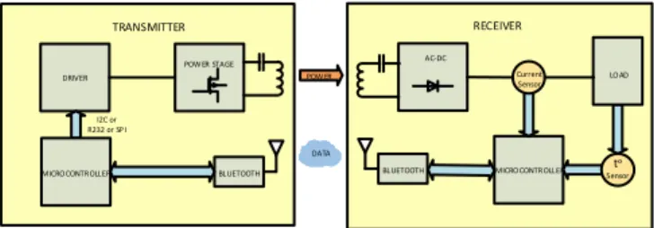
DRIVER POW ER STAGE I2C or R232 or SP I AC-DC LOAD BLUETOOTH Current Sensor tᵒ Sensor MICROCONTROLLER Communication POW ER BLUETOOTH TRANSMITTER RECEIVER DATA MICROCONTROLLER
Fig.1. Block diagram of wireless power transfer system.
The transmitter consists of a driver, a power stage, a transmitting coil and a microcontroller. The receiver side includes a receiving coil, an AC-DC rectification, a microcontroller and a current and temperature sensors respectively. The load is the EV battery. For the coordination between the transmitter and receiver and for operation optimization of the WPT system, a set of microcontrollers is in development.
A data transmission system with higher frequencies, i.e., on the order of GHz allows increasing the data transmission rate. In the case of exchange of information on advanced wireless transmission systems, several communication technologies could be adopted, such as Bluetooth, Wi-Fi, ZigBee [1],[11]. In this case the Bluetooth technology was adopted due to the fact that this standard is a compromise in terms of the data rate/efficiency/cost.
The schematic representation of a WPT system is shown in Figure 2. The schematic representation of a WPT system consisting on a two coils, where VS is the AC
power source, RSis the resistance of the power source,
1
R ,L1andC1 are respectively the primary parasitic
resistor, inductance and resonant capacitor, M12 is the mutual inductance between the primary and the secondary,R2,L2andC2are respectively the secondary
parasitic resistor, inductance and resonant capacitor, RL
is the load resistance.
RL RS C1 R1 L1 L2 R2 C2 M12
Primary coil Secondary coil
i2
VS
i1
Fig. 2. Schematic representation of a WPT system.
The Kirchhoff’s voltage law for the primary is given by
S s i j M i v C j L j R R 1 12 2 1 1 1 ) 1 (
(1)
The Kirchhoff’s voltage law for the secondary is given by
0 ) 1 ( 2 121 2 2 2 i j M i C j L j R RL
(2)
The loop impedances for the two coils is given by
12 12 12 12 1 C j L j R R Z SL
(3)
The currents of primary and secondary are given by
2 12 2 2 1 2 1 M Z Z v Z I S
(4) 2 12 2 2 1 12 2 M Z Z v M j I S
(5)
At the resonance condition the reactive part of the impedance of the coils becomes zero. Therefore, at the resonant frequency the currents I1 and I2 can be
simplified given by 2 12 2 2 1 2 1 ' ' ' M R R V R I S
(6) 2 12 2 2 1 12 2 ' 'R M R V M j I S (7)
where R1'andR2' respectively are the total transmitting
and receiving circuit resistances, is given by
1 1' R R R S L R R R2' 2
The power of the input side Pin and output power
delivered to the load Pout is given by
cos 1 I V Pin S
2
2 12 2 2 1 2 2 12 2 2 2 ' 'R M R V M R R I Pout L L S The power transfer efficiency is given by
cos ) ' ' ( ' 1 2 2 122 2 2 12 2 M R R R M R P P L in out
In (12) the power transfer efficiency is a function of the frequency and circuit parameters.
The efficiency decreases quickly when drift away from its resonant operation. High quality factor Q can increase the efficiency of the WPT system operating at resonance frequency.
3. Experimental Results
Electromagnetic interference (EMI) is important especially for the digital and analogue systems operating at 30 MHz to 300 MHz frequencies, where any circuit element becomes an antenna and can cause interference. The analysis was concentrated on the EM radiation caused by converter operating at 20 kHz switching frequency, at which the studied WPT system operates. In principle, the EMI from a relatively low frequency, as expected in case, probably will be not so strong.
The Bluetooth technology operates at the frequency of 2.4 GHz which is enough higher than the first harmonic of the power transfer frequency (20 kHz). In order to verify this hypothesis some measurements and analysis were done.
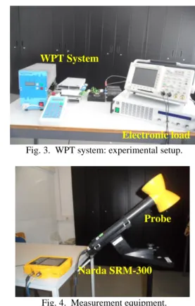
The test equipment used to perform measurements was composed by an experimental setup of WPT system and the measurement system. The WPT system is shown in Figure 3 and consists of a high frequency power source, transmitting resonant coil, receiving resonant coil and electronic programmable load. The measurement equipment is shown in the Figure 4 consist of a basic unit, measuring instrument Narda SRM-3000 Selective Radiation Meter, a portable field strength meter, PMM 8053A, and antennas in 100 kHz ÷ 3 GHz frequency domain for the measurement of electromagnetic fields.
Fig. 3. WPT system: experimental setup.
Fig. 4. Measurement equipment.
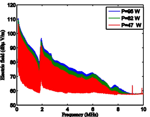
The electric field intensity in WPT system for different power transferred levels taken in the Power Electronics Laboratory is shown in Figure 5. Figure 5 shows some disturbance at the frequency 1.9 MHz which may be
WPT System
Electronic load
Probe
caused by the heavy consumption of nearby located smartphone. Because of this, in order to prevent external electromagnetic interference, the next series of measurements will be made inside a Faraday cage. The results of electric field intensity in WPT system for different distances between the WPT equipment and the probe are shown in Figure 6.
The harmonic generation from WPT system operating at 20 kHz frequency is shown in Figure 7.
Fig. 5. Electric field intensity in WPT system for different levels of transferred power.
The used measurement equipment was capable to analyze frequencies starting from 100 kHz, so the amplitudes of the harmonics were measured starting from the 5th harmonic, corresponding to 100 kHz.
Fig. 6. Electric field intensity in WPT system for different distances.
To obtain the 1st harmonic and the 3rd harmonic amplitudes, the minimum squares method was used. Using the method of minimum squares the experimental data were adjusted with a coefficient of determinationR2 0.9685 .
The high value obtained for R2 value indicates that the trendline quite precisely fits the data. The amplitudes of the harmonics including the 1st harmonic and the 3rd one generated by WPT system is shown in Figure 8. The practical values of the
electric field E in function of distance from the WPT system is shown in Fig. 9.
Fig. 7. Harmonic generation from the WPT system operating at 20 kHz frequency.
Fig. 8. Amplitude of the harmonics generated by the WPT system.
Fig. 9. Electric Field amplitude at the distance from the WPT system.
Figure 9 shows the electric field is much stronger directly adjacent to the WPT system but falls off rapidly with the distance.
The aim of these measurements is the evaluation of the electromagnetic fields levels generated by WPT systems. In order to estimate the electromagnetic interference impact on data wireless channel, it is necessary to evaluate the bit error rate (BER), the packet error rate (PER), or throughput of the communication system. The most usual method to evaluate receiving quality of data wireless channel, including the effect of interference
and disturbance in industrial wireless communication, is to check the PER. The PER is the percentage of the number of packets that failed to be received correctly to the number of whole packets transmitted. The PER is also one of the factors determining system throughput and latency [13].
The Bluetooth communication performance was evaluated using the free software Iperf3 and Wireshark. Initially Bluetooth communication between two laptops placed in the operating area of WPT system was established. One of the laptops was used as a server and another one as a client. The server created data streams and sent them to the client using the software Iperf3 [14]. A network protocol analyzer Wireshark was used to capture frames and determine the PER. It can capture and analyze packets to determine those ones that were lost by transmission errors [15].
Fig. 10. Wireshark Capture file.
The Wireshark capture file is shown in Fig. 10. The results confirmed that there were no packets with transmission errors, so it can be considered that the studied WPT system does not influence the data wireless channel operating at 2.4 GHz frequency.
4. Conclusion
In this paper was presented a study related to the electromagnetic interference impact of Wireless Power Transfer system on data wireless channel. The wireless data transmission is important to improve the efficiency of the wireless power transfer. The consideration about choosing the wireless data technology was also presented. From the described technologies, the Bluetooth can be considered one of the solutions for the data transmission in Wireless Power Transfer systems. To prevent external electromagnetic interference the measurements of the electromagnetic fields generated by Wireless Power Transfer system were taken in the Faraday cage.
The levels of electromagnetic fields due to the Wireless Power Transfer system are present. In order to estimate the possible impact of the electromagnetic interference on data wireless channel the evaluation of packet error rate was made.
The results of experiments confirmed that there is no significant impact from Wireless Power Transfer system operating at 20 kHz frequency on data transfer channel operating at 2.4 GHz frequency.
Acknowledgments
This work is funded by Portuguese Foundation for Science & Technology, through IDMEC, under LAETA, project UID/EMS/50022/2013.
References
[1] S. Li, and C. Mi, “Wireless power transfer for electric vehicle applications”, IEEE Journal of Emerging and Selected Topics in Power Electronics, vol. 3, pp. 4–17, 2015.
[2] A. Kurs, A. Karalis, R. Moffatt, J.D. Joannopoulos, P. Fisher, and M. Soljaćić, “Wireless power transfer via strongly coupled magnetic resonances”, Science Express, vol. 317, pp. 83–86, 2007.
[3] T. Imura, H. Okabe, and Y. Hori, “Basic experimental study on helical antennas of wireless power transfer for electric vehicles by using magnetic resonant couplings”, in: IEEE Vehicle Power and Propulsion Conference, 936-940, Dearborn, USA, September, 2009.
[4] C. Zhu, K. Liu, C: Yu, M. Rui, and H. Cheng, “Simulation and experimental analysis on wireless energy transfer based on magnetic resonances”, in: IEEE Vehicle Power and Propulsion Conference, 1–4, Harbin, China, September, 2008.
[5] C-T. M. Wu, J.S. Sun, and T. Itoh, “A simple self-powered AM-demodulator for wireless/data transmission”, in: 42th European Microwave Conference, 325-328, Amsterdam, Holland, October, November, 2012. [6] G.V. Tibajia, and M.C. Talampas, “Development and evaluation of simultaneous wireless transmission of power and data for oceanographic devices”, in: IEEE Sensors, 254–257, Limerick, Ireland, October, 2011.
[7] G.B. Hmida, H. Ghairani, and M. Samet, “Design of a wireless power and data transmission circuits for implantable biomicrosystem”, Biotechnology, vol. 6, pp. 153–164, 2007.
[8] T. Bieler, M. Perrottet, V. Nguyen, and Y. Perriard, “Contactless power and information transmission. IEEE Transactions on Industry Applications”, vol. 38, pp. 1266-1272, 2002.
[9] C. Rathge, and D. Kuschner, “High efficient inductive energy and data transmission system with special coil geometry”, in: 13th European Conference on Power Electronics and Applications, 1-8, Barcelona, Spain, September 2009.
[10] V.N. Yashchenko, D.S. Kozlov, and I.B. Vendik, “Dual-mode resonator for the dual-band system of wireless energy transfer with simultaneous data transmission”, Progress In Electromagnetics Research Letters, vol. 50, pp. 61–66, 2014.
[11] Y. Yokoi, A.Taniya, M. Horiuchi, and S. Kobayashi, “Development of kW class wireless power transmission system for EV using magnetic resonant method”, in: 1st International Electric Vehicle Technology Conference, 1-6, Yokohama, Japan, May 2011
[12] S. Obayashi, and H. Tsukahara, “EMC issues on wireless power transfer”, in: International Symposium on Electromagnetic Compatibility, 601–604, Tokyo, Japan, May 2014.
[13] M. Matsuzaki, “Reliability and stability of field wireless”, Yokogawa Technical Report, English Edition, vol. 55, pp. 15–18, 2012.
[14] ESnet: https://fasterdata.es.net/performancetesting/ network-troubleshooting-tools/iperf-and -iperf3/, 2015. [15] U. Lamping, R. Sharpe, and E. Warnicke, “Wireshark