Design & Implementation of Zero Voltage Switching Buck Converter
Texto
Imagem


Documentos relacionados
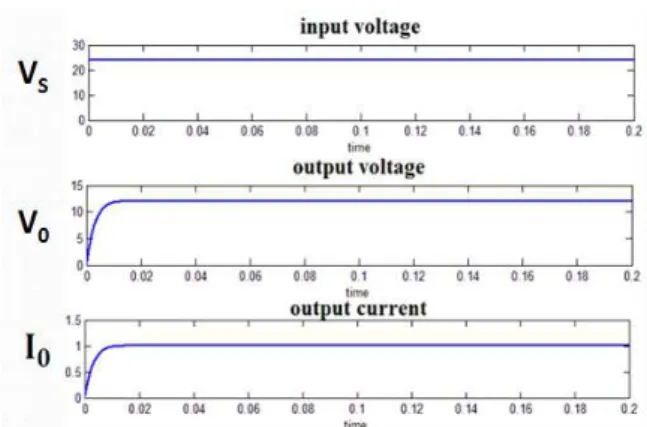
The measurement results show that the Buck converter is supplied with an input voltage of 1V and switching frequency of 155 kHz, an low power consumption (14uW), an output
The results obtained are the voltage and current peaks of the output signal, the DC power consumption, output power, switching power loss and the drain and overall efficiency.
“Analysis of a Zero Voltage Transition Boost Converter using a Soft Switching Auxiliary Circuit with Reduced Conduction Losses”, in IEEE Power Electronics Specialists Conference
The switching task is verified in simulation and also using the PEOPLER-II, in addition to walking, rolling, turning and spinning.. In the switching task, the continuity of the
these LF components in idcin spectrum are responsible for fm interharmonics in iacin spectrum. It is rather well known from power electronics that for the analysis of SPC in
In general, the DM noise is related to switching current and the CM noise is related to capacitive coupling of switching voltage with Line Impedance Stabilizing Network (LISN),
At first the converter have hard switching in main switch and completely analysis then added auxiliary circuit for soft switching Auxiliary circuit in the converter is not only
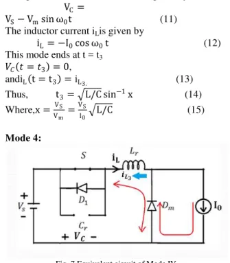
In order to increase the voltage gain in this topology, a boost converter used in series with the output stage of sepic converter, therefore the output voltage of
