American Journal of Engineering Research (AJER)
2016
American Journal of Engineering Research (AJER)
e-ISSN: 2320-0847 p-ISSN : 2320-0936
Volume-5, Issue-3, pp-01-06
www.ajer.org
Research Paper Open Access
w w w . a j e r . o r g
Page 1
Design and Development of SMS Based Generator Start/Stop
System
KESHINRO K. K
1., BALOGUN W. A
2., OYETOLA J. B
3., OMOGOYE S. O
41,2
Department of Computer Engineering, Lagos State Polytechnic Ikorodu, Lagos State, Nigeria
3,4
Department of Elect/Elect, Lagos State Polytechnic Ikorodu, Lagos State, Nigeria
ABSTRACT :
This paper offers an integrated SMS alert and remote control system for a generator. This unit can be integrated into any diesel generator. The Generator can be Started or Stopped by sending an SMS to the generator from anywhere in the world. Used in conjunction with the alert, the generator can be turn on and off even if the owner is not at home or the office when the lights go out. The SMS unit is mounted inside the generator housing (space permitting) and runs off the generators battery. When the generator is in automatic mode it will start-up when the power fails and in doing so sends an SMS to operators predetermined phone number. The methodology used was the principle of serial communication with embedded system. Sim900 was used as the GSM module and 8051 microcontroller was program, the simulation of the schematics diagram was done using Proteus 8.4 software. The microcontroller code was done using keil compiler and the hex file was transfer to proteus software for simulation.The unique SMS Alert and command system allows users to quickly and easily control their Generator worldwide, with the knowledge that problems can be sorted out quickly and efficiently. In addition to that, the
security system allows for safe and secure use without interference.
Keywords:
Generator, 8051, Microcontroller, KEIL, SMS, SIM900I.
Introduction
This Paper is a very good example of embedded system as all its operations are controlled by intelligent software inside the microcontroller. The aim of this paper is to control i.e. to ON/OFF of generator, the electrical or electronic appliances connected to this system from anywhere in the world. For this purpose user can use any type of Mobile. This way it overcomes the limited range of infrared and radio remote controls[5]. Using the convenience of SMS, this paper lets you remotely control equipment by sending plain text messages, such as "abcdn1", "abcdnaf3", "abcdf57n142"– all of which can be pre-programmed into the controller and easily remembered later. It can control up to eight external devices Short Message Service (SMS) is defined as a text-based service. That enables up to 160 characters to be sent from one mobile phone to another. In a similar vein to email, messages are stored and forwarded at an SMS centre, allowing messages to be retrieved later if you are not immediately available to receive them. Unlike voice calls, SMS messages travel over the mobile
network„s low-speed control channel[7].
"Texting", as its also known, is a fast and convenient way of communicating. In fact, SMS has taken on a life of its own, spawning a whole new shorthand language that„s rapidly Many industries have been quick to make use of this technology, with millions of handsets currently in use. As new models with "must have" features hit the market, older models become virtually worthless and if not recycled, end up in landfill[8].
II.
Review of Related Works
Amit sachen et al have discussed the user can send commands in the form of SMS messages to read the remote electrical parameters. This system also can automatically send the real time electrical parameters periodically (based on time settings) in the form of SMS. This system can be designed to send SMS alerts whenever the Circuit Breaker trips or whenever the Voltage or Current exceeds the predefined limits. This project makes use of an onboard computer which is commonly termed as microcontroller [1].
w w w . a j e r . o r g
Page 2
in analog. The analog type controller cannot be processed precisely due to the distortions and noises coming from the data. In order to increase data accuracy, the controller needs to be digitalized [2]Vimalraj et al have described a distribution transformers have a long service life if they are operated under good and rated conditions. However, their life is significantly reduced if they are overloaded, resulting in unexpected failures and loss of supply to a large number of customers thus effecting system reliability. This system provides flexible control of load parameters accurately and also provides effective means for rectification of faults if any abnormality occurs in power lines using SMS through GSM network [3].
Andriy Palamar et al proposed the system the Cellular phone containing SIM (Subscriber‟s Identifying Module) card has a specific number through which communication takes place. The mode of communication is wireless and mechanism works on the GSM (Global System for Mobile communication) technology. Here, the communication is made bi- directional where the user transmits and also receives instructions to and from the system in the form of SMS [4].
III.
Methodology
The method used for the design and implementation are as followsa. Power supply stage
Step 1: Connect one of the ac section of the bridge rectifier to the ac output of the transformer
Step 2: Connect the other teminal of the ac output of the bridge rectifier to the ac output of the transformer Step 3: Connect the ac input of the transformer to 22ov ac power source
Step 4: Connect the positive terminal of the bridge rectifier to the positive positive terminal of c1 Step5 : Connect the negative terminal of the bridge rectifier to the negative terminal of c1 Step 6: Connect the positive of c1 to the input of 7812
Step 7: Connect the negative of c1 to the ground of 7812
Step 8: Connect the output of 7812 to the input of 7805 and bias with the positive of c2 to prevent the capacitor from heating and to allow a stable voltage
Step 9: Connect the ground of 7805 to the ground of 7812 Step 10: Measure your output voltage
Step 11: The 12v output voltage will be measured from the 7812 and the 5v output will be measure from 7805
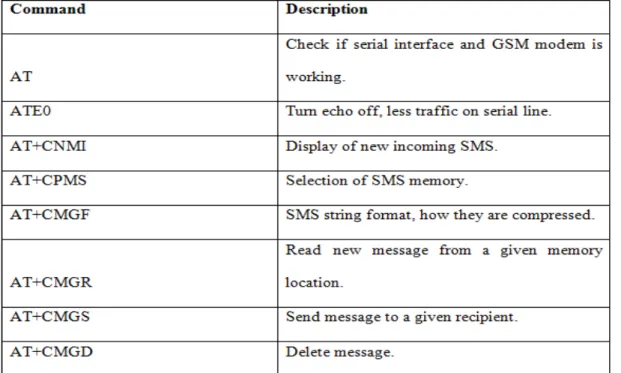
b. Programming of the gsm module
The programming of the gsm module was done using the ATCommand Instruction.
Table 1: ATCOMMAND Instruction
w w w . a j e r . o r g
Page 3
c. Programming of the microcontroller
The following steps were implemented
Step 1: The component used are 33pf capacitor, at89s52, 11.0592mhz crystal, 10uf 16v, 10k resistor, reset button
Step 2: Mount a 40pin ic socket onto the veroboard
Step 3: Connect 11.0592mhz crystal across pin18 and pin19 Step 4: Connect the 33pf across the crystal
Step 5: Connect the reset button
Step 6: Download keil on the internet and install it
Step 7: Program the sms based generator start/stop using embedded c Step 8: Compile the program, testrun, debug and generate hex file Step 9: Load the hex file into the chip with the help of burner ORG 00H
MOV R0,#10 MOV R1,#10 MOV R2,#10 MOV R3,#10 MOV TMOD,#01H MOV TCON,#00H MOV TL0,#F4H MOV TH0,#FFH SETB TR0
;#########################;
; START OF MAIN PROGRAM ;
;#########################;
L1: JNB TF0,L1
CPL P1.0 CLR TF0 MOV TL0,#F4H MOV TH0,#FFH DJNZ R0,L1 CPL P1.1 MOV R0,#10 DJNZ R1,L1 CPL P1.2 MOV R1,#10 DJNZ R2,L1 CPL P1.3 MOV R2,#10 DJNZ R3,L1 CPL P1.4 MOV R3,#10 SJMP L1
;#########################;
; END OF MAIN PROGRAM ;
;#########################; END
d. Connection of the generator to the embedded device
The device can be used with any type of generator . it was used with both key starter and the one that are not using key. Some other condition was also observed based on demand. The output of the device was connected to H-BRIGE before connecting to a generator.
e. Relay Driver Section
w w w . a j e r . o r g
Page 4
f. Complete Circuit Diagram
Fig 1: Developed Circuit Diagram of SMS based Generator Source: designed with Proteus Software (www.proteus.com)
GSM (SMS) Controlled DC Motor is automatic control system which capable of receiving a set of command instructions in the form of Short message service and performs the necessary actions like Start , Stop and speed control. I will be using a dedicated modem/mobile at the receiver module i.e. with the robot it self and send the commands using SMS service as per the required actions. The mobile unit which is dedicated at the motor driver is interfaced with an intellectual device called Micro controller so that it takes the responsibility of reading the received commands in the form of SMS from the mobile unit and perform the corresponding predefined tasks such as motor start, stop, motor direction and speed control at different levels etc.
IV.
Test and Result
4.1 Testing of Power Supply
4.2 Testing of the Generator Unit
The Generator can be Started or Stopped by sending an SMS to the generator from anywhere in the world. Used
in conjunction with the alert you can decide when to turn on and off your generator even if you‟re not at home
or the office when the lights go out.
w w w . a j e r . o r g
Page 5
4.3 Testing of the Load with Generator
System is controlled by SMS commands: start, stop, status, timer on, timer off.
i. Requesting "status" it returns: Load in Amps (which tells me that the pump is working fine), running time, and whether timer is currently activated or not.
ii. The generator starts up connected to a small load, about 0.4A for a ceiling fan, but is disconnected from the pump. The startup sequence is:
Step 1: Give start signal to generator
Step 2: Check current sensor to see if output is more than 0.4A, if not shut down generator and send error message that generator failed to start
Step 3: Wait for 2minutes
Step 4: Close pump relay
Step 5: Check current sensor to make sure the pump came on, if not shut down generator and send error message.
Step 6: The shutdown sequence is in reverse and also uses the current sensor to make sure everything is off as it should be.
V.
CONCLUSION AND RECOMMENDATION
5.1 Conclusion
There are so many industries which need 24 hours power. So they develop their own mini power plants. If there are any faults in main system at that time we make manual operation to run mini power plant generator. Due to this there is so much time consume. Here, if we provide this system so there are no needs of manual operation and we get constant power in very short time. We can get the feedback from generator, whenever the fuel level goes below the normal level. The same thing is applicable for any change in temperature of the system. Also if any parameter goes below the preset limit, also a feedback message is there from the circuit and also generator stop to working. This procedure is applicable in any kind of fault also
5.2 Recommendation
We are interfacing the circuit with GSM module so that generator can be operated from remote place. In this system if we send sms (START), the generator starts working and if we send sms (STOP), the generator stops working. Also, we can get the feedback from generator, whenever the fuel level goes below the normal level. The same thing is applicable for any change in temperature of the system. To achieve this, testing will need to be carried out to create a useful system. The report consists of a background into the area of 8051 microcontroller and mobile communication, how they are interfaced to each other and AT (Attention) commands set used in communication. The microcontroller pulls the SMS received by phone, decodes it, and recognizes the Mobile no. The switches on the relays attached to its port to control the appliances. After successful operation, controller sends back the acknowledgement to the user‟s mobile through SMS. Future work can focus on fault diagnosis of the generator using embedded system and developed a NEURO FUZZY expert system
REFERENCE
[1] A. Sachan, “Microcontroller based Based Substation Monitoring and Control System with Gsm Modem” IOSR Journal of
Electrical and Electronics Engineering, vol. 1, no. 6, (2012).
[2] M. Sarsamba “The Load Monitoring and Protection on Electricity Power lines using GSM Network”, International Journal of
Advanced Research in Computer Science and Software Engineering, vol. 3, no. 9, (2013).
[3] S.Vimalraj, R.B. Gausalya, “GSM Based Controlled Switching Circuit between Supply Mains and Captive Power Plant”,
International Journal of Computational Engineering Research, vol, 03, no. 4, (2013).
[4] A. Palamar “Control System for a Diesel Generator and UPS Based Microgrid”, Scientific Journal of Riga Technical University
Power and Electrical Engineering, vol. 27, (2010).
[5] GSM Multiple Access Scheme, http://www.eecg.toronto.edu/~nazizi/gsm/ma/ William Stallings Data and Computer
Communications 7th Edition: Chapter 9 Spread Spectrum, http://juliet.stfx.ca/~lyang/csci-465/lectures/09-SpreadSpectrum-new.ppt
[6] ETS 300 608. Digital Cellular Telecommunication System (Phase 2); Specification of the Subscriber Identity Module-Mobile
Equipment (SIM-ME) Interface. European Telecommunications Standards Institute., May 1998.
[7] ETR 100. European Digital Cellular Telecommunication System (Phase 2); Abbreviations and Acronyms. European
w w w . a j e r . o r g
Page 6
[8] Jörg Eberspächer and Hans-Jörg Vögel. GSM switching, services and Protocols. John Wiley and Sons, 1999.
[9] Klaus Vedder GSM: Security, Services, and SIM. State of the art in Applied Cryptography. Course on Computer Security and
Industrial Cryptography. Leuven, Belgium, June 3-6, 1997.
[10] J. Wu and A. H. Aghvami, \A new adaptive equalizer with channel estimator for mobile radio communications," IEEE
Transactions on Vehicular Technology,
[11] A. Clark and R. Harun,Assessment of kalman-_lter channel estimators for an HF radio link," IEE Proceedings, vol. 133, pp. 513{521, Oct 1986.
[12] ETS 300 502. European Digital Cellular Telecommunication System (Phase 2); Teleservices Supported by a GSM Public Land