Nuno André Carvalho Sousa
Patterned surfaces of poly (lactic
acid) and starch – poly (lactic acid)
blend prepared by reverse breath
figures, the effect of: solvent,
substrate and vapour
N uno Andr é Car valho Sousa P atterned sur
faces of poly (lactic acid) and st
arch – poly (lactic acid) blend prepared b
y rever
se breat
h figures, t
he ef
Dissertação de Mestrado
Ciclo de Estudos Integrados Conducentes ao Grau de
Mestre em Engenharia Biomédica
Área de Especialização: Biomateriais, Reabilitação e
Biomecânica
Trabalho realizado sob a orientação do
Professor Doutor Rui Luís Reis
Nuno André Carvalho Sousa
Patterned surfaces of poly (lactic
acid) and starch – poly (lactic acid)
blend prepared by reverse breath
figures, the effect of: solvent,
substrate and vapour
Acknowledgements
Gostaria de agradecer ao Professor Rui Reis por todo o apoio como orientador deste projecto. Pela sua disponibilidade e compreensão que sempre demonstrou e, principalmente, pelo encorajamento constante em prol de um trabalho cada vez melhor. Agradeço ainda à Doutora Ana Rita Duarte, pela sua ajuda e todos os úteis conselhos, pela paciência e por todo o apoio, obrigado.
Pelo incentivo em integrar o programa ERASMUS e pela ajuda no planeamento desse período da minha vida gostaria de agradecer ao Professor João F. Mano.
Gostaria também de agradecer a todos os investigadores e staff do grupo 3B’s – Biomateriais, Biodegradáveis e Biomiméticos
I would like to thank Professor Claudio Migliaresi and Doctor Devid Maniglio the guidance and transmitted knowledge, but also to everybody in BIOTech Center that directly or indirectly contributed to my work for make me feel at home and teach me something that any university or school could ever teach me: practical knowledge. Thank you all very much!
To my unforgettable friends, from all over the world, made during this short but rich period of my live, I would like to thank you all.
E obrigado David por teres partilhado esta experiência comigo. Obrigado Maria
Um obrigada a todos os meus colegas e amigos de Engenharia Biomédica da Universidade do Minho, que ao longo destes últimos anos partilharam todo o tipo de experiências e histórias comigo.
A toda a minha família, primos, tios e avós, muito obrigado.
Abstract
Thin polymeric films and patterns hold great promise for several applications. Many micro or nanofabrication techniques allow designing regular and ordered materials. With these techniques, good architecture reproducibility as well as porosity control of the structure can be obtained, using a vast range of polymers, including biodegradable (natural or synthetic) polymers. This work dealt with the fabrication of patterned surfaces with regular geometry by using templating techniques, breath figures (BF) and reverse breath figures (RBF) in an in-house built microfabrication system.
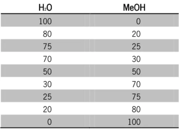
For this purpose we have prepared biodegradable polymeric patterns of poly (lactic acid) (PLA) and a starch – poly (lactic acid) blend (SPLA) with different morphologies in this in-house built system. The PLA and SPLA dissolved in chloroform and toluene (TL) (1%wt) were exposed to a vapour atmosphere with mixtures of water (H2O) and methanol (MeOH). Three types of
patterned surfaces were obtained, particles, porous films or an intermediate pattern, where both particles and film coexist.
The structures developed, by this novel approach to create biodegradable materials using a natural based polymer, could have potential applications in tissue engineering or cell growth, by themselves or as a coating for other materials. These applications consist in the use a combination of living cells and a support structure in which cell attach, grow and proliferate. Due to this kind of potential applications of the materials created, they should meet specific characteristics; in particular the used material should be non-toxic and possess high cell/tissue biocompatibility so that they will not give rise to any unfavorable behavior. Moreover, it should have a determinate surface to permit cell adhesion.
Scan electron microscopy (SEM) imaging was used to observe the morphology of the structures created Thermal analysis differential scanning calorimetry (DSC) and gel permeation chromatography (GPC) were carried out to characterize the PLA. Also the cell adhesion and growth on the surfaces created was tested. This was performed with the aid of MTS assay, fluorescence microscope and SEM.
After MTS evaluation proved the non-cytotoxicity of the materials, preliminary biological tests were done by seeding on the surfaces osteoblasts cell lines. SEM imaging and fluorescence microscopy evidenced morphology and cell adhesion and growth behavior over the patterns.
Resumo
Filmes poliméricos finos e superfícies com padrões são uma grande promessa para diversas aplicações. Muitas técnicas de micro ou nano-fabricação permitem projetar materiais regulares e ordenados. Estas técnicas permitem boa reprodutibilidade, arquitetura, bem como o controle da porosidade da estrutura, usando uma vasta gama de polímeros, incluindo polímeros biodegradáveis (naturais ou sintéticos). Este trabalho lidou com o fabrico de superfícies com padrões de geometria regular, utilizando técnicas de templating, breath figures (BF) e reverse breath figures (RBF) utilizando um sistema de microfabricação.
Para este efeito, preparamos superfícies biodegradáveis com diferentes morfologias, de poli (ácido láctico) (PLA) e uma mistura de amido - poli (ácido láctico) SPLA neste sistema. PLA e (SPLA) dissolvido em clorofórmio e tolueno (TL) (1 % em peso) foram expostos a uma atmosfera de vapor com misturas de água (H2O) e metanol (MeOH). Três tipos de superfícies com padrões
foram obtidos, partículas, filmes porosos ou um padrão intermédio, onde partículas e filme poroso coexistem.
As estruturas desenvolvidas, por esta nova abordagem para criar materiais biodegradáveis, utilizando um polímero natural, podem ter potenciais aplicações em engenharia de tecidos ou para crescimento de células, por si próprias ou como revestimentos de outros materiais. Estas aplicações, usam uma combinação de células vivas e uma estrutura de apoio na qual a célula se pode aderir, crescer e proliferar. Devido a estas possíveis aplicações dos materiais obtidos, estes devem atender a características específicas, em particular o material deve ser não-tóxico, e possuir boa biocompatibilidade, para que não dê origem a qualquer comportamento prejudicial. Além disso, ele deve ter uma determinada superfície para permitir a adesão celular.
Microscopia eletrônica de varrimento (SEM), foi utilizada para analisar a morfologia das estruturas criadas, análises térmicas: varredura diferencial de calorimetria (DSC) e cromatografia de permeação de gel (GPC), foram realizadas para caracterizar o PLA. Também a adesão celular e crescimento nas superfícies criadas foi testado. Esta foi realizada com o auxílio de ensaio MTS, microscopia de fluorescência e SEM. Depois da avaliação por MTS comprovar a não citotoxicidade dos materiais, testes preliminares biológicos foram feitos através do seeding de uma linha celular de osteoblastos sobre as superfícies criadas. SEM evidenciou padrões de
Table of contents
Acknowledgements ... iii Abstract ... v Resumo ... vii Abbreviations ... xiii List of Figures ... xvList of Tables ... xix
General Introduction ... 1
1| Motivation and outline ... 3
2| Polymeric films formation ... 5
2.1. Replication techniques ... 5
2.1.1. Microimprinting lithography ... 5
2.1.2. Soft lithography ... 6
2.2. Rapid prototyping techniques ... 6
2.2.1. Three-dimensional printing ... 7
2.2.2. Laser stereolithography ... 7
2.3. Laser micropatterning ... 8
3| Microsphere production methods ... 8
3.1. Single emulsion technique ... 8
3.2. Double emulsion technique ... 9
3.3. Microfluidics ... 9
3.4. Polymerization techniques ... 10
3.4.1. Normal polymerization ... 10
3.4.2. Interfacial polymerization ... 10
3.5. Phase separation coacervation technique ... 11
3.6. Spray drying and spray congealing ... 11
3.7. Solvent extraction ... 11
4| Breath figures pattern ... 12
4.1. Historical considerations ... 13
4.2. Influencing factors for BF formation ... 14
5.1.2. Tissue engineering and cell growth ... 18
5.2. Polymers of natural origin ... 19
5.2.1. Starch ... 20
5.3. Synthetic polymers ... 21
5.3.1. Poly (Lactic Acid) - PLA ... 22
6| Starch and poly (lactic acid) blends ... 23
7| Conclusion and future perspectives ... 23
8| References ... 24
Materials and Methods ... 29
1| Materials ... 31
2| Methods ... 31
2.1. PLA and SPLA solutions ... 31
2.2. Microspheres production and porous films creation ... 31
2.3. Characterization ... 33
2.4. Surface tension and contact angle ... 33
2.5. Differential scanning calorimetry (DSC) ... 34
2.6. Gel permeation chromatography (GPC) ... 34
2.7. In vitro studies ... 35
2.7.1. Cell seeding and culture ... 35
2.7.2. Cell adhesion and morphology ... 35
2.7.3. Cell viability assay ... 35
Patterned Surfaces of Poly (Lactic Acid) and Starch – Poly (Lactic Acid) Blend
Prepared by Reverse Breath Figures, the Effect of: Solvent, Substrate and Vapour
... 37
1| Introduction ... 40
2| Materials and methods ... 43
2.1. Materials ... 43
2.2. Methods ... 43
2.2.1. PLA and SPLA solutions ... 43
2.2.2. Microspheres production and porous films creation ... 43
2.2.3. Characterization ... 45
2.2.4. Contact angle ... 45
2.2.5. Differential scanning calorimetry (DSC) ... 45
2.2.6. Gel permeation chromatography (GPC) ... 45
2.3. In vitro studies ... 46
2.3.1. Cell seeding and culture ... 46
2.3.2. Cell adhesion and morphology ... 46
2.3.3. Cell viability assay ... 46
3| Results and discussion ... 47
3.1. Mechanism of ordered porous/particles patterns formation ... 47
3.2. Influence of temperature, substrate and solution concentration ... 48
3.3. Solvent influence ... 53 3.4. Non-solvent influence ... 57 3.5. Intermediate conditions ... 59 3.6. Polymer influence ... 62 3.7. Cell culture ... 64 4| Conclusions ... 69 5| References ... 70
General Conclusions and Future Perspectives ... 73
1| General conclusions and future research ... 75
Abbreviations
AAO Anodic Aluminum Oxide
BF Breath Figures
CAD Computer-Aid Design
CHCl3 Chloroform
CS2 Carbon Disulfide
DSC Differential Scanning Calorimetry
GPC Gel Permeation Chromatography
H2O Water
HSP Hansen Solubility Parameters
MeOH Methanol
MW Molecular Weight
O/W Oil/Water
O/W/O Oil/Water/Oil
PDMS Polydimethylsiloxane
PET Polyethylene Theraphthalate
PLA Poly (Lactic Acid)
PPEs Poly(Paraphenylene Ethynylene)s
PPS Poly(Para-Phenylene)-Block-PS
PS Polystyrene
RBF Reverse Breath Figures
RED Relative Energy Difference
SE Secondary Electron
SEM Scan Electron Microscopy
SPLA Starch – Poly (Lactic Acid) Blend
SPS Star Polystyrene
TE Tissue Engineering
Tg Transition Temperature
List of Figures
Figure 1.1. SEM of a 50 mm thick PDMS membrane with 100 mm holes [12]. ... 5
Figure 1.2. SEM images of anodic aluminum oxide (AAO) nanomold having nanopores for hot embossing method [16]. ... 6
Figure 1.3. Porous film produced by soft lithography [17]. ... 6
Figure 1.4. Cellular-type structure produced by laser stereolithography [13]. ... 7
Figure 1.5. Schematic diagram of O/W emulsion solvent evaporation method, adapted from [27]. ... 9
Figure 1.6. Optical microscopy images of polyTPGDA particles, by microfluids [30]. ...10
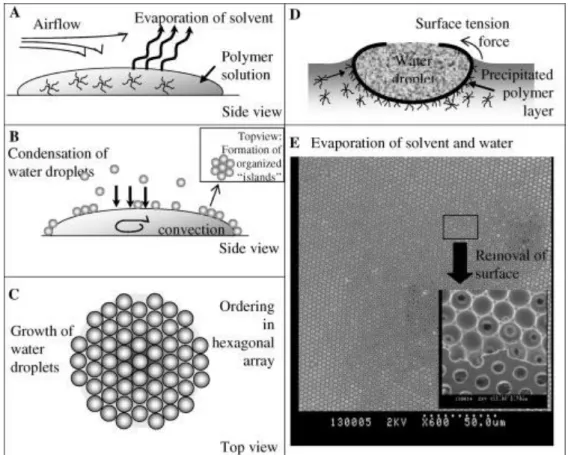
Figure 1.7. Mechanism for the formation of honeycomb-structured, porous films: (A) evaporation of the solvent of the polymer solution, (B) condensation of water droplets cause by the cold surface temperature of the solution, (C) formation of a hexagonal closest packing of water droplets on the solution surface, (D) precipitation of the polymer on the interface and prevention of coagulation, and (E) scanning electron microscopy photograph of a porous film after the evaporation of the solvent and water (the small photograph shows the removal of the surface by adhesive tape). Reproduced from [39]. ...13
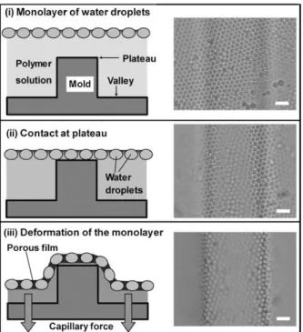
Figure 1.8. Schematic illustrations (side views) and corresponding snapshots (top views; bar: 10 μm) from the in-situ observation for the bas-relief pattern-imprinting process. Reproduced from [15]. ...16
Figure 1.9. Microsphere patterns prepared by reverse breath figures method [50]. ...16
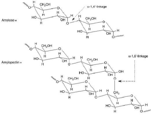
Figure 1.10. Molecular structure of starch. ...21
Figure 1.11. Chemical formula of PLA adapted from [70]. ...23
Figure 2.1. a) Static system for breath figures; b) flow system for breath figures. ...31
Figure 2.2. Mechanism of breath figures creation, adapted from [1]. ...32
Figure 3.1. Flow system for breath figures. ...43
Figure 3.2. Mechanism of breath figures creation, adapted from [8]. ...44
Figure 3.3. Method for a) spheres creation; b) porous films creation, adapted from [8]. ...48
Figure 3.4. Microscopy picture of the process, a) before the polymer introduction and b) after the polymer introduction. ...49 Figure 3.5. SEM of spheres/particles created for process optimization at 50ºC a) – d) glass,
b) solvent water, solvent chloroform; c) solvent methanol, solvent toluene; d) non-solvent methanol, non-solvent chloroform (scale bar - 20μm). ... 54 Figure 3.8. SPLA structures created and size distribution a) non-solvent water, solvent toluene; b) solvent water, solvent chloroform; c) solvent methanol, solvent toluene; d) non-solvent methanol, non-solvent chloroform (scale bar - 20μm). ... 55 Figure 3.9. a) PLA - toluene drop over 50% - 50% of MeOH Water solution for contact angle measurement, resulting "sphere"; b) 25% - 75% of MeOH Water solution drop over PLA - toluene for contact angle measurement, resulting porous film. ... 58 Figure 3.10. Contact angle of: a) water - MeOH mixtures over polymer solution, and b) polymer solution over water - MeOH mixtures. ... 59 Figure 3.11. Co-existence of structures, with porous spheres/semi-spheres: a) PLA – TL with a 50:50 atmosphere; b) SPLA - TL with a 20:80 water methanol atmosphere and spheres inside the pores: c) PLA – chloroform with a 75:25 atmosphere; d) SPLA – chloroform with a 75:25 atmosphere. ... 60 Figure 3.12. SEM results for SPLA - chloroform solutions using a water methanol mixtures as non-solvent, a) water, to b) 80:20, c) 75:25, d) 70:30, e) 50:50, f) 30:70, g) 25:75, h) 20:80, i) MeOH; (scale bar: 10 μm). ... 61 Figure 3.13. (a); Txy diagram for methanol/water (b) activity coefficient plot for methanol/water [40]. ... 61 Figure 3.14. PLA GPC for molecular weight determination. ... 63 Figure 3.15. Thermograph of PLA grains and thermograph of PLA film after dissolution in chlorophorm. ... 64 Figure 3.16. MTS results for cell growth after 24 hours of culture. ... 65 Figure 3.17. Cell growth on glass a) after 24 h and b) after 72 h (scale bar 200 μm)... 65 Figure 3.18. Cell growth on PLA structures: porous film a) after 24 h, b) after 72 h; intermediate pattern c) after 24 h, d) after 72 h and spheres e) after 24 h and f) after 72 h (scale bar 200 μm). ... 66
Figure 3.20. SEM images of cells over a) porous film pattern (PLA – chloroform, 100:0 vapour phase) after 24 h; b) glass after 72 h; c) microspheres pattern (PLA – chloroform, 0:100 vapour phase) after 24 h; d) microsphere pattern (SPLA – toluene, 0:100 vapour phase) after 72 h; (scale bar 200 μm). ...69
List of Tables
Table 1.1. Average molecular weight (MW) of potato and wheat amyloses. ...21
Table 3.1. Range of H2O:MeOH (%) used as non-solvent during the process. ... 45
Table 3.2. Surface tension of solvents and non-solvents depending of the temperature [31, 32]. ... 52 Table 3.3. Physical properties of solvents and non-solvents [31]. ... 54 Table 3.4. HSP parameters for PLA, solvents and non-solvents and their affinity [20, 35-38] 56 Table 3.5. values for non-solvent affinity for solvent. ... 57 Table 3.6. Surface tension in mN/m for the specified mass % at 25 ºC, for aqueous solution [31]. ... 61
CHAPTER I.
1| Motivation and outline
Biodegradable structures have an important role in many therapies techniques existing an increasing interest in the way these materials can be obtained [1].
This ambitious goal requires interdisciplinary research strategies combining expertise from biology, chemistry, engineering and materials science. Also a biomimetic approach is considered due to the advance of the nature all over the years gave the organisms the advantage to live with the characteristics obtained [2].
The advances in fabrication technologies have enhanced the tools available to create clinically important therapeutic applications. Biodegradable polymers naturally degrade and disappear in tissue over a desired period of time, being applied to the successful fabrication of a variety of implantable and oral drug delivery devices. Biodegradable polymer conduits and tissue engineering scaffolds are produced using extrusion, fiber bonding, salt leaching, and laminating. However, micro and nanofabrication of biodegradable polymers with precise control over surface microarchitecture, topography, and size remains an important challenge, once some of the methods, such as thin-film deposition, photolithography, and etching, are not suitable for biodegradable polymers. Significant effort has been devoted to develop novel fabrication techniques for biodegradable polymers in the recent years [1-4].
The aim of this work was to prepare biodegradable structures, as films or microspheres, composed of poly (lactic-acid) and a starch - poly (lactic-acid) blend as a framework. A very interesting way to form these films with a honeycomb structure is the Breath Figures method. This technique allows also the creation of microspheres, with some differences, being called Reverse Breath Figures.
The potential applications of such structures are much extended. However, nowadays the effects on cell growth of structures with organized surfaces are well proven, being one of the most interesting applications for such materials. Studies focusing on cell behavior on surfaces with micrometer-sized features revealed that such surfaces can influence the cell behavior, showing the interest of this interaction of cells with patterned surfaces [5, 6]. So, it is evident that patterning methods, such as microfabrication techniques, can provide biocompatible surfaces that control cellular interactions using a combination of living cells and a support structure in which the attachment, grow and proliferation of the cells can occur [7].
Due to the nature of the applications of this kind of material, the materials should meet specific characteristics like non-toxicity, and a high cell or tissue biocompatibility. Moreover, it should have a determinate surface to permit cell adhesion [8].
The present chapter provides an overview of the microspheres production techniques and of the developments in micro- and nanofabrication technologies that allow the production of patterned surfaces, having the templating techniques used in this work a further discussion.
Additionally, the focus will be on how the knowledge obtained using these materials can be incorporated to design biocompatible materials for various biomedical applications such as basic cell biology, as referred before for the porous films case, or drug delivery systems, for microspheres, referring also the materials considered more suitable for this applications.
2| Polymeric films formation
Microfabrication technology has been applied to the successful fabrication of a variety of materials, including implantable devices based on silicon, glass, silicone elastomer, or plastic materials [9-11], Figure 1.1.
Figure 1.1. SEM of a 50 mm thick PDMS membrane with 100 mm holes [12].
2.1. Replication techniques
Replication technologies are useful for biodegradable polymer microfabrication. The principles of these processes are well known, being one of the most important principles the replication of a mold tool [12-14]. This represents the inverse geometry of the desired polymer structure. One advantage of this technique is that the expensive microfabrication step is restricted to the fabrication of this tool. Its form can be replicated many times as wanted into the polymer substrate. Other benefit offered is the freedom of design: the master can be fabricated with a large number of different microfabrication technologies, which allow various geometries [13, 15].
2.1.1. Microimprinting lithography
One example of these replication techniques is microimprinting lithography. It is also known as hot embossing or compression molding [13, 16].
It uses a mold to transfer the geometric micropatterns to the biodegradable polymer, Figure 1.2. It is a fast and relatively inexpensive technique, capable of patterning nano-scale features on a planar surface. However, the polymer used needs a good thermal stability near the glass transition temperature (Tg) [13, 15, 16].
Figure 1.2. SEM images of anodic aluminum oxide (AAO) nanomold having nanopores for hot embossing method [16].
2.1.2. Soft lithography
Soft lithography is also based on self-assembly and replica molding for micro and nanofabrication. In this technique, an elastomeric stamp with patterned relief structures on its surface is used to generate patterns and structures. This elastomeric stamp is the essential element of this technique. It can be prepared by cast molding a crosslinkable elastomer over a mold with surface relief structures [13, 15, 17].
It allows the creation of structures with sizes ranging from 30 nm to 100 μm. Soft lithography is also an effective and lowcost method that has been widely used in micro/nanofabrication of biomaterials [13, 17].
Figure 1.3. Porous film produced by soft lithography [17].
2.2. Rapid prototyping techniques
Differing from the replication techniques, the fabrication process for rapid prototyping is controlled by computer-aid design (CAD) of a certain component. These techniques have been applied to manufacturing components with complex geometries [13].
1 mm
Methods including direct deposition, which is essentially micro-scale extrusion, selective laser sintering, three-dimensional printing, and stereolithography have been used in these methods [13, 18].
2.2.1. Three-dimensional printing
Three-dimensional printing has the capability to fabricate microstructures with a high controll and resolution, also for the interior of the component. Also aided by a CAD model, it builds the desired material layer by layer with detailed information for every layer. Each layer consists in a thin distribution of powder spread over the surface of a powder bed. This powder is bounded by a material, selectively where the object is to be formed by a technology similar to ink-jet printing. The support of the powder lowers and the next powder layer can be spread repeating the process all over again, until the part is completed, when unbound powder is removed, leaving the fabricated part [13, 19].
2.2.2. Laser stereolithography
Similar to three-dimensional printing this technique distinguishes by working in a liquid environment. It is a method that allows real three-dimensional microfabrication. A 3D model designed with CAD software is sliced into series of 2D layers of equal thickness. A motorized x– y–z platform immersed in a liquid photopolymer generates each 2D layer by exposing selectively the liquid polymer exposed to a focused laser light.
Figure 1.4. Cellular-type structure produced by laser stereolithography [13]. 200 μm
The polymer solidifies in the focal point only, forming layer after layer of the object according to the design. This layer-by-layer fabrication technique enables complex internal features such as complex passageways and curved surfaces [13].
2.3. Laser micropatterning
Using lasers to pattern biodegradable polymers, the setup this technique consists of four main parts: a laser system, a beam delivery system, a micrometer-resolution x–y sample stage, and an online monitoring system. Different patterns such as microholes or micron-sized channel type patterns can be obtained [13].
Another potential for laser ablation is surface modification of microfabricated structures with new structures formation[13].
3| Microsphere production methods
Other important kind of polymeric materials are microspheres. Over the past 25 years, biodegradable polymer microspheres have been investigated mostly for drug delivery applications, including but not limited to vaccines, tumor treatment, drug delivery, and control of inflammation, depending on microsphere physical properties such as polymer molecular weight, monomer composition, and microsphere size [9, 20-24].
3.1. Single emulsion technique
The polymers dissolved in aqueous medium are then dispersed in non-aqueous medium like oil [20, 21, 25].
Emulsion–solvent evaporation method is applied to fabricate microspheres very commonly. The fabricating process consists in the complete dissolution of the polymer, followed by an emulsification. The emulsified suspension is then stirred, and the solvent is evaporated, Figure 1.6 [25-28].
Figure 1.5. Schematic diagram of O/W emulsion solvent evaporation method, adapted from [27].
3.2. Double emulsion technique
This method of microspheres preparation consists in the formation of the multiple emulsions or the double emulsion of type w/o/w. It enables the use of natural as well as synthetic polymers. The continuous phase is generally consisted of the polymer solution. The primary emulsion is subjected then to the homogenization or sonication before the addition to the aqueous solution of the polymer. This results in the formation of a double emulsion. The emulsion is then subjected to solvent removal either by solvent evaporation or by solvent extraction [20, 21, 28, 29].
3.3. Microfluidics
This is a versatile strategy to produce monodisperse solid particles with sizes from 20 to 1000 μm. The method involves the formation of monodisperse liquid droplets by using a microfluidic device and shaping the droplets in a microchannel and then solidifying these drops in situ either by polymerizing a liquid monomer or by lowering the temperature of a liquid that sets thermally. This method offers the possibility to produce particles with an exceptionally narrow range of sizes Figure 1.6. A new level of control over the shapes of the particles is also allowed. About the mechanism for droplet formation, it allows the use of a wide variety of materials including gels, metals, polymers, and polymers doped with functional additives. This procedure can be scaled up to produce large numbers of particles [30, 31].
Figure 1.6. Optical microscopy images of polyTPGDA particles, by microfluids [30].
3.4. Polymerization techniques
The polymerization techniques conventionally used for the preparation of the microspheres are mainly divided in two groups, normal polymerization and interfacial polymerization. Both are carried out in liquid phase [20].
3.4.1. Normal polymerization
It is carried out using different techniques as bulk, suspension, precipitation, emulsion and micellar polymerization processes. In bulk, a monomer or a mixture of monomers along with the initiator or catalyst is usually heated to initiate polymerization. Polymer so obtained may be molded as microspheres. Suspension polymerization also referred as bead or pearl polymerization. It is carried out by heating the monomer or mixture of monomers as droplets dispersion in a continuous aqueous phase. The droplets may also contain an initiator and other additives. Emulsion polymerization differs from suspension polymerization as due to the presence of the initiator in the aqueous phase, which later on diffuses to the surface of micelles. Bulk polymerization has an advantage, the formation of pure polymers [20].
3.4.2. Interfacial polymerization
It involves the reaction of various monomers at the interface between the two immiscible liquid phases to form a film of polymer that essentially envelops the dispersed phase [20].
One of the advantages is the rapid polymerization, initiated by ions present in the medium. The monomer dissolved in a mixture of oil and organic solvent, is then slowly extruded through a needle into a well-stirred aqueous solution containing surfactant. The resulting colloidal suspension can be concentrated by evaporation under vacuum. The main disadvantage of this
3.5. Phase separation coacervation technique
This process is based on the principle of decreasing the solubility of the polymer in organic phase to affect the formation of polymer rich phase called the coacervates. In this method, a solution of the polymer to which an incompatible polymer is added causing the phase separation of the first polymer. Addition of non-solvent results in the solidification of polymer. PLA microspheres have been prepared by this method by using butadiene as incompatible polymer [33]. The process variables are very important since the rate of achieving the coacervates determines the distribution of the polymer film, the particle size and agglomeration of the formed particles. The agglomeration must be avoided by stirring the suspension using a suitable speed stirrer since, as the process of microspheres formation begins, the formed polymerize globules start to stick and form the agglomerates. Therefore the process variables are critical, as they control the kinetic of the formed particles since there is no defined state of equilibrium achievement [20, 26].
3.6. Spray drying and spray congealing
These methods are based on the drying of the mist of the polymer and drug in the air. Depending upon the removal of the solvent or cooling of the solution, the two processes are named spray drying and spray congealing respectively. The polymer is first dissolved in a suitable volatile organic solvent such as dichloromethane, acetone, etc. This is then atomized in a stream of hot air. The atomization leads to the formation of small droplets or a fine mist from which the solvent evaporates instantaneously leading the formation of the microspheres in a size range 1-100 μm. Microparticles are separated from the hot air by means of the cyclone separator while the traces of solvent are removed by vacuum drying. One of the major advantages of the process is feasibility of operation under aseptic conditions [20, 26, 34].
3.7. Solvent extraction
Also called solvent evaporation method, it is used for the preparation of microparticles, involves removal of the organic phase by extraction of the organic solvent. The method involves water miscible organic solvents such as isopropanol. Organic phase is removed by extraction with water. This process decreases the hardening time for the microspheres. The rate of solvent
removal by extraction method depends on the temperature of water, ratio of emulsion volume to water and the solubility profile of the polymer [10, 20, 27].
4| Breath figures pattern
Each microfabrication offers specific characteristics and advantages, although, there are reasons why a particular device would not be microfabricated. If only a few devices are needed and the dimensions are reasonable, it is often possible to machine them conventionally. Microfabrication, usually, has long development times, depending on the complexity of the system [35].
So, besides the traditional processes that can be used to obtain patterned surfaces, more recent alternative methodologies have been suggested. One of the methods to create materials with microstructured surfaces with increasing interest, being referred as a convenient and cheap method, utilizes the condensation of monodisperse water droplets on polymer solution, forming honeycomb porous films, usually known as breath figures method [6].
The fabrication strategies for this process are based in two features: firstly the size of the template is fixed, and also the template is often sacrificial but, in most cases, not produced with trivial ease, particularly if monodisperse templates are employed. A dynamic templating method for polymers and other materials that utilizes a nontoxic and easily available templating medium would be an attractive proposition: Breath figures, the fog created by exhaling onto a cold surface, fit that bill and are able to create periodic structures within a size range of 50 nm to 20 μm, i.e., over almost three orders of magnitude. Figure 1.7 presents the mechanism for breath figures creation.
These polymeric materials nanostructured and microstructured, have many potential applications that had already been proposed and still remain to be explored. Firstly, they can be used in many places where porous materials or spheres are required, such as light-weight materials or drug delivery systems [36]. At the same time, the highly ordered nature of the pore arrays brings about many new possible applications. One is the use as photonic-band-gap materials, which have attracted much research attention recently. Another is the use in biology for cell culturing and tissue engineering and in optoelectronics such as solar cells. Moreover, they
Several trials have been made to utilize this simple method to make suitable macroporous films for different applications.
Figure 1.7. Mechanism for the formation of honeycomb-structured, porous films: (A) evaporation of the solvent of the polymer solution, (B) condensation of water droplets cause by the cold surface temperature of the solution, (C) formation of a hexagonal closest packing of water droplets on the solution surface, (D) precipitation of the polymer on the interface and prevention of coagulation, and (E) scanning electron microscopy photograph of a porous film after the evaporation of the solvent and water (the small photograph shows the removal of the surface by adhesive tape). Reproduced from [39].
4.1. Historical considerations
The formation of water droplets on solid surfaces was first investigated by Aitken in 1893 and later, in 1911, by Rayleigh. The foggy arrays of water droplets on surfaces were named breath figures because of their mode of generation. Knobler and Beysens investigated the formation of BF further and found that they are formed, not only on solid surfaces, but on liquids as well, specifically on paraffin oil. Knobler was the first to note the hexagonal pattern that BF forms on paraffin oil. He realized also that water droplets do not coalesce immediately when they touch, due to a thin film of oil separating them [40]
(BF arrays, BF) when a drop of the polymeric solution in carbon disulfide was exposed to a flow of moist air. Francois and co-workers claimed that the BF were formed by a Marangoni-type convection of condensing water droplets; it was concluded that SPS and block copolymers, containing a PS sequence, were useful for forming polymer BF [40, 41]. It was reasoned that only such polymers would be able to encapsulate the water droplets with a thin polymer membrane. Srinivasarao and Han independently demonstrated that carboxylated as well as unmodified PS form highly ordered and well-developed bubble arrays when cast from CS2 and
chloroform, respectively. Neither a block copolymer nor SPS architecture seems necessary for the formation of BF [40, 42].
4.2. Influencing factors for BF formation
The exact mechanism of BF formation is not known in detail. Each given class of polymer or material system that forms BF could operate by a slightly different mechanism [43, 44]. It may not be a single, generally applicable mechanism for BF formation. There are, however, important information that can be drawn from published data. An attractive mechanism for the gestation of BF was developed by Srinivasarao: the formation and subsequent solidification of BF was recognized as the root cause for the hexagonally arranged arrays of air bubbles in thin polymer films [42, 45]. When moist air is blown over a surface of the polymer solution its temperature decreases. Water droplets nucleate on the surface and subsequently grow. After some time, non-coalescing droplets form and organize on the surface into a hexagonally ordered and highly mobile array. These arrays do not coalesce, but start to sink into the solution of the polymer. The remaining solvent and the water are evaporated after, leaving a monolayer. In all cases, however, an imprint of the water droplets, now as an air bubble array, is left in the polymeric matrix [44-47].
4.3. Some literature results review
As referred before, the mechanistic of BF formation is complex, even being considered a simple templating methodology, it has complex thermodynamic, kinetic, and entropic fundaments that are widely discussed but not well defined [39, 40].
Even with the difficulty to completely understand the complex process some information can be obtained from the results present in the publish data. Linear PS does not form well-ordered bubble arrays under most conditions. However, linear PS does form BF under some conditions, for example carboxylate-terminated (PS) dissolved in CS2, or a linear
non-end-functionalized PS in chloroform, had successful formed honeycomb microporous films. The same was claimed for other polymers, like mostly polymers with spherical shapes (either block copolymers or star polymers) considered to form bubble arrays. However, under the correct conditions, rigid-rod conjugated polymers such as poly(paraphenylene ethynylene)s (PPEs), polythiophenes, polyfluorenes, and nitrocellulose alike form well-developed and monodisperse BF as well [39, 40].
Different forms of the pores and conformations of the films can be obtained by this technique. Distorting the hexagonal arrays obtained rectangular, almost square, or triangular symmetries can be obtained [48]. Microporous films formed from poly(ε-caprolactone) or from the polyacrylamide were mechanically deformed. Hexagons are topologically equivalent to rectangles, squares, and triangles. As a consequence, it was possible to compress or stretch the microporous poly(caprolactone) films, grown on a water surface, to 0.2–4 times their original size. [38, 40, 48].
Other possibility is the use of this technique together with other microfabrication technique, resulting in interesting arrangement of the surface and structure of the materials created, Figure 1.8 [15]. This result present is obtained when the substrate used had a surface with sulks.
Figure 1.8. Schematic illustrations (side views) and corresponding snapshots (top views; bar: 10 μm) from the in-situ observation for the bas-relief pattern-imprinting process. Reproduced from [15].
4.4. Reverse breath figures for microspheres formation
Recently Xiaopeng Xiong and his coworkers beginning to wonder what would happen if the process toke place under an organic nonsolvent vapour atmosphere instead of water. Here began the concept of ―Reverse Breath Figures‖ where microsphere patterns other than honeycomb porous structure have been obtained, Figure 1.9. This results were obtained using linear and star-shaped poly(styrene-block-butadiene) copolymers dissolved in solvents such as toluene, trichloroform, and dichloromethane were cast onto the surface of glass substrate in methanol or ethanol vapour atmosphere [49].
5| Biomedical uses of microstructured films and microspheres
With an understanding of the technology, we can now examine the many applications of microfabrication to biology and medicine. Nowadays, microfabricated devices used as tools for molecular biology and biochemistry as well as for medicine (such as blood pressure sensors) is a current practice. They represent one of the few areas where microfabrication has already made a large impact on biomedical field [3, 7]. Though, microfabricated devices can also be used to interrogate and manipulate cells themselves [6].
For the case of microspheres, they are most employed in the administration of medication. Microspheres offer advantages relatively to others materials because they can be ingested or injected; they can be tailored for desired release profiles and in some cases can even provide organ-targeted release. They also hold sufficient strength and durability.
5.1. Biodegradable polymers for microstructured films and microspheres
The use of biodegradable polymers for biomedical applications has increased dramatically, over the past decade. The most important biomedical applications of biodegradable polymers are in the areas of controlled drug delivery systems, in the forms of implants and devices for bone and dental repairs [51]. They showed to be non-toxic and biocompatible as well as their degradation products which, in most cases, occur naturally in the body.
They are also suitable, and many times the most obvious option for the kind of structures studied in this work, as for the case of the spheres, mostly used in controlled drug delivery systems usually fabricated from biodegradable polymers.
For the case of the porous films, the microfabrication systems have been successful employed to fabricate polymeric devices. However, the usual methods create structures that when implanted remain in the biological tissue if not removed surgically. However, the recovery of these small-scale devices from tissues is difficult. For this the application of biodegradable polymers that would naturally degrade and disappear in tissue over a desired period of time, like the one created in this study is considered advantageous. Micro and nano-fabrication or pattern techniques with precise control over surface microarchitecture, topography, and size are still an important challenge in this area of biodegradable polymers [52-54].
5.1.1. Controlled drug delivery
As referred previously, the most common methods of sustained drug delivery are as injectable micro or nanospheres or as subcutaneous implant systems, which involve some diffusion or erosion matrix [55, 56]. Controlled drug delivery has applications not only in medicine but also in veterinary and agrochemical fields [51].
The initial drug release systems involved incorporation of the active substance into a polymer matrix, which can be implanted into the patient in various ways. The surface erosion is particularly important for drug delivery systems and with lower drug loading more effective entrapment occurs, and although it has been shown that porosity is initially poor, surface erosion does occur followed by greater water penetration [13, 51, 57].
5.1.2. Tissue engineering and cell growth
Advances in tissue culture and tissue engineering have generated research into novel methods of producing biodegradable networks that are effective for a variety of applications both as hard and soft scaffolds.
Biodegradable polymeric films, like the ones obtained in this work, have been applied in cell growth or tissue engineering with success [58, 59]. They offer a number of advantages over other materials for developing materials for in tissue engineering. The key advantages include the ability to tailor mechanical properties and degradation kinetics to suit various applications. The fabrication into various shapes with desired pore morphologic features conducive to tissue in-growth is also an interesting point of investigation for this kind of structures and materials [59].
Attempts to find tissue-engineered solutions to cure different injuries have made necessary the development of new polymers that meet a number of demanding requirements. These requirements range from the ability of the material to provide mechanical support during tissue growth and gradually degrade to biocompatible products to more demanding requirements such as the ability to incorporate cells or growth factors, when talking of scaffolds [60].
Many of the currently available degradable polymers do not fulfill all of these requirements and significant chemical changes to their structure may be required if they are to be formulated for such applications [61].
time frame required for the application, processability to complicated shapes with appropriate porosity, ability to support cell growth and proliferation, and appropriate mechanical properties [3].
Biodegradable polymers can be either natural or synthetic. The general criteria for selecting a polymer for use as a degradable biomaterial are to match the mechanical properties and the degradation rate to the needs of the application.
5.2. Polymers of natural origin
Economic and environmental aspects are contributing to the growing interest in natural polymers as choice for biodegradable materials, due to their low toxicity, low manufacture costs, low disposal costs, and renewability. Different natural materials have been studied and proposed for the preparation of scaffolds in tissue engineering (TE), such as proteins (collagen, silk fibroin), polysaccharides chitosan, hyaluronic acid, alginates, starch-based materials, bacterial cellulose, dextrans), and microbial origin polyesters [62, 63].
Regarding natural polymers, polysaccharides are the most frequently employed in biomedical applications Polysaccharides consist of a large variety of polymers biosynthesized in wood, plants, algae, and marine crustaceans, but also produced by bacteria and fungi. They may be structural components, provide carbon and energy reserves for cells or may be excreted as plant exudates or as microbial exopolysaccharides. They are characterized from a wide range of glycosidic linked structures based on about 40 different monosaccharides [62-64].
Polysaccharides may be homopolysaccharides, composed of a single monosaccharide unit, or heteropolysaccharides, containing two or more sugar moieties. They can be linear or branched, and may have single or mixed linkage between monosaccharides units. Various substituent, such as acyl groups, amino acids or inorganic residues can be present in polysaccharides structure. The widest diversity of polysaccharides is produced by prokaryotic cells, although many carbohydrate polymers may derive from eukaryotes (algae, plants, or animals) [62].
Polysaccharides have a great number of properties which makes them an excellent material for tissue engineering applications, such as non-toxicity, renewability, water solubility, stability to variations of pH, and they can be chemically modified to achieve high swelling in water
as well as being biofunctionalized. However, they have low mechanical, thermal, and chemical stability [62].
5.2.1. Starch
Among the natural polymers, starch is one of most interest polysaccharides. It is regenerated from carbon dioxide and water by photosynthesis in plants. Owing to its complete biodegradability, low cost and renewability, starch is considered as a promising candidate for developing sustainable materials. In view of this, starch has been receiving growing attention over the last years. Many efforts have been exerted to develop starch-based polymers for conserving the petrochemical resources, reducing environmental impact and searching more applications. Other reason why it is a promising polymer is because of its inherent biodegradability, overwhelming abundance and renewability. It is composed of a mixture of glycans that plants synthesize and deposited in the chloroplasts as their principal food reserve [62, 64, 65].
Starch is mainly composed of two homopolymers of D-glucose amylase, a mostly linear D(1, 4’)-glucan and branched amylopectin, having the same backbone structure as amylose but with many -1, 6’-linked branch points, Figure 1.10. There are a lot of hydroxyl groups on starch chains making it evidently hydrophilic. Starch has different proportions of amylose and amylopectin ranging from about 10–20% amylase and 80–90% amylopectin depending on the source. Amylose is soluble in water and forms a helical structure. Starch occurs naturally as discrete granules since the short. Starch granules exhibit hydrophilic properties and strong inter-molecular association via hydrogen bonding formed by the hydroxyl groups on the granule surface. The hydrophilicity of starch can be used to improve the degradation rate of some degradable hydrophobic polymers, which will be shown in. Starch is totally biodegradable in a wide variety of environments. It can be hydrolyzed into glucose by microorganism or enzymes, and then metabolized into carbon dioxide and water. It is worth noting that carbon dioxide will recycle into starch again by plants and sunshine. Starch itself is poor in processability, also poor in the dimensional stability and mechanical properties for its end products. Therefore, native starch is not used directly [64-67].
Figure 1.10. Molecular structure of starch.
The molecular weight of starch from different origins is present in Table 1.1. Table 1.1. Average molecular weight (MW) of potato and wheat amyloses.
Starch x Potato - 7.0 9.0 8.7 Wheat - 5.1 3.9 5.8
5.3. Synthetic polymers
Biodegradable polymers chemically synthesized are widely used as biomaterials in tissue engineering because they typically offer high versatility, stable properties and good workability. Also, they are flexible polymers, predictable and easily processable into different size and shapes. The physical and chemical properties of a polymer can be modified and the mechanical and degradation characteristics can be altered by their chemical composition of the macromolecule
range of shape and properties can be obtained; furthermore the final result is more predictable. Degradation rate of scaffolds can be adapted to the required applications by selecting specific polymers, copolymers or blends. Most of these polymers undergo to a simple hydrolytic degradation. However, biocompatibility of synthetic polymers is generally lower then natural polymers. in vivo. Among the most used of these bioresorbable polymers, as implantable devices, is poly (lactic acid) (PLA) or blends of this [2, 60].
5.3.1. Poly (Lactic Acid) - PLA
PLA is one of the most important biodegradable polyesters with many excellent properties and has been widely applied in many fields, especially for biomedical area. PLA possesses good biocompatibility and processability, as well as high strength and modulus. However, PLA is very brittle under tension and bend loads and develops serious physical aging during application. Moreover, PLA is a much more expensive material than the common industrial polymers [68-71].
Poly (lactic acid) (PLA) belongs to the family of aliphatic polyesters commonly made from
- hydroxy acids, which include polyglycolic acid or polymandelic acid, and are considered biodegradable and compostable. PLA is a thermoplastic, high-strength, high-modulus polymer that can be made from annually renewable resources to yield articles for use in either the industrial packaging field or the biocompatible/bioabsorbable medical device market. It is easily processed on standard plastics equipment to yield molded parts, film, or fibers. It is one of the few polymers in which the stereochemical structure can easily be modified by polymerizing a controlled mixture of the L- or D-isomers to yield high-molecular-weight amorphous or crystalline polymers. Chemical structure of PLA is present in Figure 1.11. PLA is degraded by simple hydrolysis of the ester bond and does not require the presence of enzymes to catalyze this hydrolysis. The rate of degradation is dependent on the size and shape of the article, the isomer ratio and the temperature of hydrolysis. PLA degradation is dependent on time, temperature, low-molecular-weight impurities, and catalyst concentration. Catalysts and oligomers decrease the degradation temperature and increase the degradation rate of PLA. In addition, they can cause viscosity and rheological changes, fuming during processing and poor mechanical properties [68,
Figure 1.11. Chemical formula of PLA adapted from [70].
6| Starch and poly (lactic acid) blends
This polymers have been proved to allow the formation of structures as microspheres or films when used isolated [21, 73, 74]. However when compared to conventional petroleum polymers, PLA is more expensive and degrades slowly in the environment over a period of several months to 2 years. Starch, on the other hand, is a low price material, derives from abundant and readily available sources. What is more, the biodegradation rate of starch is rapid. Also, its small granule structure makes it good as a particulate filler in polymer blend systems [64, 68, 75, 76].
Many efforts have been made to develop PLA/starch blends to reduce total raw materials cost and enhance their degradability. The major problem of this blend system is the poor interfacial interaction between hydrophilic starch granules and hydrophobic PLA. Mechanical properties of blends of PLA and starch using conventional processes are very poor because of incompatibility. The major problem with this blend system is the poor interfacial interaction between the hydrophilic starch granules and the hydrophobic PLA [76-78].
7| Conclusion and future perspectives
Microfabrication systems are now much developed and allow the use of biodegradable polymers, synthetic or natural as well as the combination of both.
Each fabrication technique has important characteristics and advantages, and, by employing newly developed fabrication techniques, with manufacturing costs and biocompatibility in mind, we have the unique ability to engineer a micro or nano-scale biomaterial.
These kinds of techniques provide great flexibility and control of the structures. The use of more than one methodology allows also approaches that lead to new technologies and structures created.
Some important methods for the preparation of nanoparticulate, together with their advantages and disadvantages, were also summarized in this work, as important biodegradable structures.
There are now numerous preparation methods available for particles producing, and important technological advances have been achieved. Simple, safe, and reproducible techniques are now available to prepare spheres. Depending on the characteristics needed, it is now possible to choose the best method of preparation and the best polymer to achieve the desired results.
Despite these technological challenges, nanoparticles have shown great promise for many applications, in particular biomedical applications such as drug delivery systems.
The need to be non-toxic or the simplification of the procedure to allow economic scale-up, are things to have in mind when producing this kind of materials both for microspheres and porous films.
The technique described by Rayleigh and Aitken, breath figures, at the beginning of the 20th century was proved to be a reliable choice to create ordered structures. The BF method is a simple and effective templating tool, with potential applications as cell-growth media, and refractive-index materials, and, if smaller bubbles are examined, for photovoltaic applications. Outstanding issues remain, such as making very small and very large pores reliably and from any polymeric material. Effective backfilling to obtain compounded micro- and nanoscale materials presents exciting challenges to be met in the future of these arrays.
It is a versatile technique, that recently have showed to be a facile way to prepare a microsphere pattern, with some differences leading to the reverse breath figure method. The advantage of this approach is its simplicity: a microsphere pattern can be obtained by simply casting a polymer solution onto a glass substrate in the vapour of up to the complete evaporation of the solvent, when talking of reverse breath figures. The porous film pattern can be as easily obtained replacing the vapour phase for water instead of an organic solvent.
8| References
3. Khademhosseini, A., et al., Microscale technologies for tissue engineering and biology. Proceedings of the National Academy of Sciences of the United States of America, 2006. 103(8): p. 2480-2487.
4. Won Mook, C. and O.O. Park, A soft-imprint technique for submicron structure fabrication via in situ polymerization. Nanotechnology, 2004. 15(1): p. 135.
5. Galeotti, F., et al., Breath figures-mediated microprinting allows for versatile applications in molecular biology. European Polymer Journal, 2009. 45(11): p. 3027-3034.
6. Alves, N.M., et al., Controlling Cell Behavior Through the Design of Polymer Surfaces. Small, 2010. 6(20): p. 2208-2220.
7. Ookura, R., et al., Stabilization of Micropatterned Polymer Films as Artificial Extracellular Matrices for Tissue Engineering. Molecular Crystals and Liquid Crystals Science and Technology. Section A. Molecular Crystals and Liquid Crystals, 1999. 337(1): p. 461-464.
8. Uchida, T., et al. Fabrication of biodegradable scaffolds by use of self-assembled magnetic sugar particles as a casting template. in Robotics and Automation, 2008. ICRA 2008. IEEE International Conference on. 2008.
9. Hans, M.L. and A.M. Lowman, Biodegradable nanoparticles for drug delivery and targeting. Current Opinion in Solid State and Materials Science, 2002. 6(4): p. 319-327. 10. Rötting, O., et al., Polymer microfabrication technologies. Microsystem Technologies,
2002. 8(1): p. 32-36.
11. Deniz, K.A. and L. Chang, Microfabrication technology for polycaprolactone, a biodegradable polymer. Journal of Micromechanics and Microengineering, 2000. 10(1): p. 80.
12. Alom Ruiz, S. and C.S. Chen, Microcontact printing: A tool to pattern. Soft Matter, 2007. 3(2): p. 168-177.
13. Lu, Y., Micro and nano-fabrication of biodegradable polymers for drug delivery. Advanced Drug Delivery Reviews, 2004. 56(11): p. 1621-1633.
14. O’Dwyer, C., et al., Atomic nanolithography patterning of submicron features: writing an organic self-assembled monolayer with cold, bright Cs atom beams. Nanotechnology, 2005. 16(9): p. 1536.
15. Ohzono, T., T. Nishikawa, and M. Shimomura, One-step fabrication of polymer thin films with lithographic bas-relief micro-pattern and self-organized micro-porous structure. Journal of Materials Science, 2004. 39(6): p. 2243-2247.
16. Lee, H., et al., Replication of nanostructures on microstructures by intermediate film mold inserted hot embossing process. Microsystem Technologies, 2008. 14(8): p. 1149-1155.
17. Vozzi, G., et al., Fabrication of PLGA scaffolds using soft lithography and microsyringe deposition. Biomaterials, 2003. 24(14): p. 2533-2540.
18. Fan, H., et al., Rapid prototyping of patterned functional nanostructures. Nature, 2000. 405(6782): p. 56-60.
19. Wu, B.M., et al., Solid free-form fabrication of drug delivery devices. Journal of Controlled Release, 1996. 40(1-2): p. 77-87.
20. Rajeev A, J., The manufacturing techniques of various drug loaded biodegradable poly(lactide-co-glycolide) (PLGA) devices. Biomaterials, 2000. 21(23): p. 2475-2490. 21. Sinha, M., USE OF BIODEGRADABLE MICRO AND NANO-PARTICLES IN VACCINE
22. Matsumoto, A., et al., A novel preparation method for PLGA microspheres using non-halogenated solvents. Journal of Controlled Release, 2008. 129(3): p. 223-227.
23. Zhao, Y., Z. Zhang, and H. Dang, Preparation of tin nanoparticles by solution dispersion. Materials Science and Engineering: A, 2003. 359(1-2): p. 405-407.
24. Haruma, K., Functional polymer microspheres. Progress in Polymer Science, 2000. 25(8): p. 1171-1210.
25. Chung, T.-W., Y.-Y. Huang, and Y.-Z. Liu, Effects of the rate of solvent evaporation on the characteristics of drug loaded PLLA and PDLLA microspheres. International Journal of Pharmaceutics, 2001. 212(2): p. 161-169.
26. Berkland, C., K. Kim, and D.W. Pack, Fabrication of PLG microspheres with precisely controlled and monodisperse size distributions. Journal of Controlled Release, 2001. 73(1): p. 59-74.
27. O'Donnell, P.B. and J.W. McGinity, Preparation of microspheres by the solvent evaporation technique. Advanced Drug Delivery Reviews, 1997. 28(1): p. 25-42.
28. Rosca, I.D., F. Watari, and M. Uo, Microparticle formation and its mechanism in single and double emulsion solvent evaporation. Journal of Controlled Release, 2004. 99(2): p. 271-280.
29. Zambaux, M.F., et al., Influence of experimental parameters on the characteristics of poly(lactic acid) nanoparticles prepared by a double emulsion method. Journal of Controlled Release, 1998. 50(1-3): p. 31-40.
30. Xu, S., et al., Generation of Monodisperse Particles by Using Microfluidics: Control over Size, Shape, and Composition. Angewandte Chemie International Edition, 2005. 44(25): p. 3799-3799.
31. Shah, R.K., et al., Designer emulsions using microfluidics. Materials Today, 2008. 11(4): p. 18-27.
32. Pinto Reis, C., et al., Nanoencapsulation I. Methods for preparation of drug-loaded polymeric nanoparticles. Nanomedicine: Nanotechnology, Biology and Medicine, 2006. 2(1): p. 8-21.
33. Thomasin, C., et al., Drug microencapsulation by PLA/PLGA coacervation in the light of thermodynamics. 1. Overview and theoretical considerations. Journal of Pharmaceutical Sciences, 1998. 87(3): p. 259-268.
34. Takashima, Y., et al., Spray-drying preparation of microparticles containing cationic PLGA nanospheres as gene carriers for avoiding aggregation of nanospheres. International Journal of Pharmaceutics, 2007. 343(1-2): p. 262-269.
35. Voldman, J., M.L. Gray, and M.A. Schmidt, Microfabrication in Biology and Medicine. Annual Review of Biomedical Engineering, 1999. 1(1): p. 401-425.
36. Freiberg, S. and X.X. Zhu, Polymer microspheres for controlled drug release. International Journal of Pharmaceutics, 2004. 282(1-2): p. 1-18.
37. Zhang, Y. and C. Wang, Micropatterning of Proteins on 3D Porous Polymer Film Fabricated by Using the Breath-Figure Method. Advanced Materials, 2007. 19(7): p. 913-916.
38. Song, L., et al., Facile Microstructuring of Organic Semiconducting Polymers by the Breath Figure Method: Hexagonally Ordered Bubble Arrays in Rigid Rod-Polymers. Advanced Materials, 2004. 16(2): p. 115-118.
40. Bunz, U.H.F., Breath Figures as a Dynamic Templating Method for Polymers and Nanomaterials. Advanced Materials, 2006. 18(8): p. 973-989.
41. Maillard, M., et al., Rings and Hexagons Made of Nanocrystals: A Marangoni Effect. The Journal of Physical Chemistry B, 2000. 104(50): p. 11871-11877.
42. Srinivasarao, M., et al., Three-Dimensionally Ordered Array of Air Bubbles in a Polymer Film. Science, 2001. 292(5514): p. 79-83.
43. Madej, W., et al., Breath Figures in Polymer and Polymer Blend Films Spin-Coated in Dry and Humid Ambience. Langmuir, 2008. 24(7): p. 3517-3524.
44. Karthaus, O., et al., Water-Assisted Formation of Micrometer-Size Honeycomb Patterns of Polymers. Langmuir, 2000. 16(15): p. 6071-6076.
45. Limaye, A.V., et al., Evidence for Convective Effects in Breath Figure Formation on Volatile Fluid Surfaces. Physical Review Letters, 1996. 76(20): p. 3762-3765.
46. Sharma, V., et al., Effect of solvent choice on breath-figure-templated assembly of ―holey‖ polymer films. EPL, 2010. 91(3): p. 38001.
47. Servoli, E., G.A. Ruffo, and C. Migliaresi, Interplay of kinetics and interfacial interactions in breath figure templating – A phenomenological interpretation. Polymer, 2010. 51(11): p. 2337-2344.
48. Nishikawa, T., et al., Micropatterns Based on Deformation of a Viscoelastic Honeycomb Mesh. Langmuir, 2003. 19(15): p. 6193-6201.
49. Xiong, X., et al., Microsphere Pattern Prepared by a ―Reverse‖ Breath Figure Method, in Macromolecules. 2009. p. 9351–9356.
50. Xiong, X., et al., Microsphere Pattern Prepared by a ―Reverse‖ Breath Figure Method. Macromolecules, 2009. 42(23): p. 9351-9356.
51. Amass, W., A. Amass, and B. Tighe, A review of biodegradable polymers: uses, current developments in the synthesis and characterization of biodegradable polyesters, blends of biodegradable polymers and recent advances in biodegradation studies. Polymer International, 1998. 47(2): p. 89-144.
52. Miller, C., et al., Oriented Schwann cell growth on micropatterned biodegradable polymer substrates. Biomaterials, 2001. 22(11): p. 1263-1269.
53. Lai, K.L., M.H. Hon, and I.C. Leu, Pattern formation on polymer resist by solvent-assisted nanoimprinting with PDMS mold as a solvent transport medium. Journal of Micromechanics and Microengineering, 2011. 21(7): p. 075013.
54. Li, G., et al., The nanofabrication of polydimethylsiloxane using a focused ion beam. Nanotechnology, 2009. 20(14): p. 145301.
55. Sinha, V.R. and A. Trehan, Biodegradable microspheres for protein delivery. Journal of Controlled Release, 2003. 90(3): p. 261-280.
56. Berkland, C., et al., Microsphere size, precipitation kinetics and drug distribution control drug release from biodegradable polyanhydride microspheres. Journal of Controlled Release, 2004. 94(1): p. 129-141.
57. Ahmed, A., C. Bonner, and T.A. Desai, Bioadhesive microdevices with multiple reservoirs: a new platform for oral drug delivery. Journal of Controlled Release, 2002. 81(3): p. 291-306.
58. Hou, X., K.-L. Choy, and J. Yan, Deposition of biodegradable poly (d,l-lactic acid) films using aerosol-assisted method. Surface and Coatings Technology, 2008. 202(21): p. 5175-5179.
![Figure 1.1. SEM of a 50 mm thick PDMS membrane with 100 mm holes [12].](https://thumb-eu.123doks.com/thumbv2/123dok_br/17919279.850285/24.892.344.598.271.467/figure-sem-mm-thick-pdms-membrane-mm-holes.webp)
![Figure 1.2. SEM images of anodic aluminum oxide (AAO) nanomold having nanopores for hot embossing method [16]](https://thumb-eu.123doks.com/thumbv2/123dok_br/17919279.850285/25.892.108.734.126.333/figure-images-anodic-aluminum-nanomold-having-nanopores-embossing.webp)
![Figure 1.4. Cellular-type structure produced by laser stereolithography [13].](https://thumb-eu.123doks.com/thumbv2/123dok_br/17919279.850285/26.892.256.685.774.1071/figure-cellular-type-structure-produced-laser-stereolithography.webp)
![Figure 1.5. Schematic diagram of O/W emulsion solvent evaporation method, adapted from [27]](https://thumb-eu.123doks.com/thumbv2/123dok_br/17919279.850285/28.892.266.664.123.418/figure-schematic-diagram-emulsion-solvent-evaporation-method-adapted.webp)
![Figure 3.3. Method for a) spheres creation; b) porous films creation, adapted from [8]](https://thumb-eu.123doks.com/thumbv2/123dok_br/17919279.850285/67.892.108.758.227.548/figure-method-spheres-creation-porous-films-creation-adapted.webp)

