Alessio Cascardi
Analytical model for shear
capacity of masonry
retrofitted with fiber
reinforced mortar layer
Anal
ytical model for shear capacity of
masonr y r e tr ofitted wit h fiber r einfor ced mor tar la yer Alessio Cascardi P or tugal | 2014 Czech university of Prague
Alessio Cascardi
Analytical model for shear
capacity of masonry
retrofitted with fiber
reinforced mortar layer
“Analytical model for shear capacity of masonry retrofitted with fiber reinforced mortar layer”
Erasmus Mundus Programme
ADVANCED MASTERS IN STRUCTURAL ANALYSIS OF MONUMENTS AND HISTORICAL CONSTRUCTIONS i
DECLARATION
Name: Alessio Cascardi
Email: [email protected]
Title of the Msc Dissertation:
“Analytical model for shear capacity of masonry retrofitted with fiber reinforced mortar layer”
Supervisor(s): Daniel Oliveira Bahman Ghiassi
Year: 2013 - 2014
I hereby declare that all information in this document has been obtained and presented in accordance with academic rules and ethical conduct. I also declare that, as required by these rules and conduct, I have fully cited and referenced all material and results that are not original to this work.
I hereby declare that the MSc Consortium responsible for the Advanced Masters in Structural Analysis of Monuments and Historical Constructions is allowed to store and make available electronically the present MSc Dissertation.
University: University of Minho
Date: July 24, 2014
“Analytical model for shear capacity of masonry retrofitted with fiber reinforced mortar layer”
Erasmus Mundus Programme ADVANCED MASTERS IN STRUCTURAL ANALYSIS OF MONUMENTS AND HISTORICAL CONSTRUCTIONS ii
“Analytical model for shear capacity of masonry retrofitted with fiber reinforced mortar layer”
Erasmus Mundus Programme
ADVANCED MASTERS IN STRUCTURAL ANALYSIS OF MONUMENTS AND HISTORICAL CONSTRUCTIONS iii
"The most beautiful thing we can experience is the mysterious. It is the source of all true art and all true science".
“Analytical model for shear capacity of masonry retrofitted with fiber reinforced mortar layer”
Erasmus Mundus Programme ADVANCED MASTERS IN STRUCTURAL ANALYSIS OF MONUMENTS AND HISTORICAL CONSTRUCTIONS iv
“Analytical model for shear capacity of masonry retrofitted with fiber reinforced mortar layer”
Erasmus Mundus Programme
ADVANCED MASTERS IN STRUCTURAL ANALYSIS OF MONUMENTS AND HISTORICAL CONSTRUCTIONS v
ACKNOWLEDGEMENTS
Only now I realize that I have reached the end of a long journey that ends with this project, to which I have devoted energy, ideas and above all enthusiasm. I wish to thank and express my gratitude to all the people who, in different ways, I have been close and they both allowed and encouraged my studies and the realization of this thesis. I would like to express my sincere appreciation and thanks to my advisors and major professors.
Firstly thank Professor Daniel Oliveira, my advisor, for the courtesy, helpfulness and professionalism with which guided me in the thesis work and for making me partaker of his deep knowledge in the scientific field. I thank you for your patience and care with which he followed every step of my work. Finding the right balance between criticism and encouragement has been able to bring out the best in me.
Dr. Bahman Ghiassi, from the beginning has given me great confidence and proved to be an excellent guide. Without him I would not have believed possible the realization of this thesis. It showed enthusiasm for the project from the very first moment when I presented it to him and was always available to advise and answer my questions.
Prof. Tiago Miranda for sharing his knowledge and experience in the proper use of Data Mining, and for criticizing constructively my work, giving me the opportunity to enhance my skills in the field of scientific research.
Prof. David Biggs for is availability and great friendship demonstrated in all the SA7 and SA8 units.
Thanks to my supervisors Italian: prof. Aiello and Micelli. They were always available for questions and advice.
“Analytical model for shear capacity of masonry retrofitted with fiber reinforced mortar layer”
Erasmus Mundus Programme ADVANCED MASTERS IN STRUCTURAL ANALYSIS OF MONUMENTS AND HISTORICAL CONSTRUCTIONS vi
***
I take advantage of this moment to thank who helped me in this special year that I will remember for a lifetime. To start from my parents to whom I dedicate this thesis, for allowing me to carry out the studies, especially for having always understood my nature independent and not having ever limited so allow me to complete my studies in a serene way. From them I received the education, example and affection as great as any son could ever want.
Thanks to all the "SKOKKIATI", always close to me and that I cannot wait to hug. I missed a lot in this year abroad, but I'm sure we'll have a lifetime to spend again together.
A special thanks to Rosalinda, that most of all kept me company from Italy. Her kindness and gentleness have made less difficult the long period of detachment and gave me the peace of mind to study in order to make the best in the exams. Thank you so much for having joked and laughed with me in difficult times making me feel "at home".
A simple “thank you” is not enough for my colleagues – Lorenzo Hofer, Michele Puliga, Josè Humberto, Andres Braga, Mafalda Guimaraes, Lasha Shartava, Dorit Cester and Leidy Bejarano – who have contributed in numerous ways to make my program a pleasant one.
I thank my computer, for not having ever abandoned.
“Analytical model for shear capacity of masonry retrofitted with fiber reinforced mortar layer”
Erasmus Mundus Programme
ADVANCED MASTERS IN STRUCTURAL ANALYSIS OF MONUMENTS AND HISTORICAL CONSTRUCTIONS vii
“Analytical model for shear capacity of masonry retrofitted with fiber reinforced mortar layer”
Erasmus Mundus Programme ADVANCED MASTERS IN STRUCTURAL ANALYSIS OF MONUMENTS AND HISTORICAL CONSTRUCTIONS viii
ABSTRACT
Structural consolidation has always been a challenge for anyone who has had to deal with and has been addressed with different approaches, more or less invasive. Alongside the traditional techniques, the application of composite materials to masonry buildings is now promising for consolidation, improvement and / or seismic adjustment. Such materials, endowed with excellent tensile strength, allow to easily put a remedy to situations that affect both the elevation and horizontal structures and, respect the interventions with traditional materials, reduced invasiveness, as they allow maintain almost unchanged the dimensions. Composite materials have been found effective in a wide series of applications and seem to be viable substitutes for the conventional materials used in intervention techniques.
A large number of existing unreinforced masonry (URM) structures are made by stone blocks and poor mortars, showing a low strength against in-plane seismic forces. The shear behaviour of masonry walls subjected to in-plane lateral forces is strongly dependent on the quality of the mortar used in the joints and on the strength of the blocks. In heritage buildings, where masonry was made by using weak materials, it is not unusual to find collapse due to sliding forces acting along the loaded diagonals of the walls, following the joints directions. Innovative consolidation techniques show efficacy in testing so the importance of guarantee analytical formula for the design of the application becomes a challenge for researchers and the development would be useful for engineers. Notice that it will only applied to existing undamaged masonry that needs strengthening.
A large test campaign on masonry panels retrofitted with fibers reinforced mortar layer was conducted by the University of Salento in cooperation with the laboratory group of University of Trento. Scope of the experiment was to verify shear capacity improvement due to the application of fibers grid in a cement mortar matrix on the masonry walls. Diagonal compressive tests were made on reinforced and un-reinforced masonry. Panels were properly prepared with very poor quality
“Analytical model for shear capacity of masonry retrofitted with fiber reinforced mortar layer”
Erasmus Mundus Programme
ADVANCED MASTERS IN STRUCTURAL ANALYSIS OF MONUMENTS AND HISTORICAL CONSTRUCTIONS ix
mortar joints in order to simulate existing masonry structures typically present on the Salento landscape.
Given the great importance of historic structures and the need to protect the existing buildings, the present work aims to present an innovative analytical model for the prediction of the masonry shear capacity retrofitted with glass or carbon fibres grids immersed in a mortar matrix. The model is implemented using a data mining technique which is able to determine relationship between parameters observed in the experimental campaign.
It is reasonable to consider the resultant model as a starting point of a large study which takes into account a new set of test designed based on the formula provided by the data mining procedure. It can, in fact, confirm the importance of the analysed parameters and it will help to plan the new test in the most useful way.
“Analytical model for shear capacity of masonry retrofitted with fiber reinforced mortar layer”
Erasmus Mundus Programme ADVANCED MASTERS IN STRUCTURAL ANALYSIS OF MONUMENTS AND HISTORICAL CONSTRUCTIONS x
“Analytical model for shear capacity of masonry retrofitted with fiber reinforced mortar layer”
Erasmus Mundus Programme
ADVANCED MASTERS IN STRUCTURAL ANALYSIS OF MONUMENTS AND HISTORICAL CONSTRUCTIONS xi
RESUMO
A consolidação estrutural sempre foi um desafio para quem tem de lidar com a mesma e tem sido tratada com diferentes abordagens, mais ou menos invasivas. A par das técnicas tradicionais, a aplicação de materiais compósitos em edifícios de alvenaria é uma técnica promissora para a consolidação e melhoramento sísmicos. Estes materiais, dotados de excelente resistência à tração, permitem encontrar uma solução para os diferentes esquemas estruturais, respeitar as intervenções baseadas em materiais tradicionais e reduzir a intrusividade, pois permitem manter praticamente inalterada a geometria original. Os materiais compósitos têm sido eficazes numa série abrangente de aplicações e parecem ser substitutos viáveis dos materiais convencionais utilizados nas intervenções.
Um grande número de estruturas de alvenaria não reforçada existentes é constituído por blocos de pedra e argamassas pobres, demostrando uma baixa resistência para forças sísmicas no plano. O comportamento ao corte de paredes de alvenaria submetidas a forças horizontais no plano é fortemente dependente da qualidade da argamassa usada nas juntas e da resistência dos blocos. Em edifícios históricos, onde a alvenaria foi executada usando materiais de baixa resistência mecânica, não é incomum encontrar situações de colapso devido a forças de corte que atuam ao longo das diagonais das paredes, seguindo as direções das juntas. As técnicas de consolidação inovadoras têm mostrado eficácia em ensaios, deste modo a importância das fórmulas analíticas para o dimensionamento é um desafio para os investigadores e o seu desenvolvimento seria útil para os engenheiros. De notar que estas são aplicadas apenas a alvenaria não danificada que necessite de reforço.
Foi realizada na Universidade de Salento uma grande campanha de ensaios em painéis de alvenaria com argamassa reforçada com fibras, em cooperação com o laboratório da Universidade de Trento. O âmbito do trabalho consistiu na verificação da melhoria da capacidade de corte devido à aplicação de malhas de fibras embebidas numa matriz de argamassa de cimento nas paredes de alvenaria.
“Analytical model for shear capacity of masonry retrofitted with fiber reinforced mortar layer”
Erasmus Mundus Programme ADVANCED MASTERS IN STRUCTURAL ANALYSIS OF MONUMENTS AND HISTORICAL CONSTRUCTIONS xii
Foram realizados ensaios de compressão diagonal em alvenaria reforçada e não-reforçada. Os painéis foram executados com juntas de argamassa de muito baixa qualidade, com o propósito de simular estruturas de alvenaria típicas da região de Salento.
Dada a grande importância das estruturas históricas e a necessidade de proteger os edifícios existentes, o presente trabalho tem como objetivo apresentar um modelo analítico inovador para a previsão da capacidade de corte da alvenaria reforçada com fibras de vidro ou fibras de carbono embebidas numa matriz de argamassa. O modelo é implementado usando uma técnica de “data mining” capaz de determinar relações entre os parâmetros observados na campanha experimental. É razoável considerar o modelo resultante como um ponto de partida de um grande estudo que tem em conta um novo conjunto de ensaios planeados com base nos resultados da técnica de “data mining”. Esta técnica poderá confirmar a importância dos parâmetros analisados e ajudar a planear os novos testes de forma mais útil.
“Analytical model for shear capacity of masonry retrofitted with fiber reinforced mortar layer”
Erasmus Mundus Programme
ADVANCED MASTERS IN STRUCTURAL ANALYSIS OF MONUMENTS AND HISTORICAL CONSTRUCTIONS xiii
“Analytical model for shear capacity of masonry retrofitted with fiber reinforced mortar layer”
Erasmus Mundus Programme ADVANCED MASTERS IN STRUCTURAL ANALYSIS OF MONUMENTS AND HISTORICAL CONSTRUCTIONS xiv
RIASSUNTO
Il consolidamento strutturale è sempre stato una sfida per chiunque abbia avuto a che fare ed è stato affrontato con approcci diversi, più o meno invasivi. Accanto alle tecniche tradizionali, l'applicazione di materiali compositi per il consolidamento di costruzioni in muratura è ora promettente, e per il miglioramento e/o adeguamento sismico. Tali materiali, dotati di ottima resistenza alla trazione, consentono di porre facilmente rimedio a situazioni che colpiscono sia strutture in elevazione sia orizzontali e, rispetto gli interventi con materiali tradizionali, presentano ridotta invasività, poiché permettono di mantenere pressoché inalterate le dimensioni dell’elemento cui sono adottate. I materiali compositi sono risultati efficaci in una vasta serie di applicazioni e sembrano essere validi sostituti per i materiali convenzionali.
Un gran numero di strutture in muratura non rinforzata (URM) esistenti è realizzato con blocchi di pietra e malta, mostrando una bassa resistenza contro le forze sismiche nel piano. Il comportamento a taglio di pareti in muratura soggetta a forze laterali nel piano è molto dipendente dalla qualità della malta utilizzata nei giunti e dalla resistenza dei blocchi. Negli edifici storici, dove la muratura è stata realizzata con materiali deboli, non è raro trovare collasso a causa di forze di scorrimento che agiscono lungo le diagonali delle pareti, seguendo direzioni articolazioni. Tecniche di consolidamento innovative mostrano efficacia nei test, così dell'importanza di garantire una formula analitica per la progettazione dell'applicazione diventa una sfida per i ricercatori e lo sviluppo sarebbe utile per gli ingegneri. Si noti che sarà applicata solo alle murature integre esistenti che devono essere rafforzate.
Una grande campagna di prove su pannelli in muratura, fortificati uno strato di malta rinforzata con una griglia di fibre, è stata condotta dall’Università del Salento in collaborazione con il gruppo del laboratorio dell'Università di Trento. Ambito dell’esperimento era verificare il miglioramento della capacità di taglio dovuta all'applicazione di una griglia di fibre immersa in una matrice di malta
“Analytical model for shear capacity of masonry retrofitted with fiber reinforced mortar layer”
Erasmus Mundus Programme
ADVANCED MASTERS IN STRUCTURAL ANALYSIS OF MONUMENTS AND HISTORICAL CONSTRUCTIONS xv
cementizia su pareti in muratura. Prove di compressione diagonale sono state compiute. I pannelli sono stati adeguatamente preparati con giunti di malta di qualità molto scarsa in modo da simulare strutture esistenti in muratura tipicamente presenti sul paesaggio salentino.
Data la grande importanza delle strutture storiche e la necessità di proteggere gli edifici esistenti, il presente lavoro si propone di presentare un modello analitico innovativo per la previsione della capacità a taglio muratura rinforzata con griglie di fibre di vetro o carbonio immerse in una matrice di malta cementizia. Il modello è implementato utilizzando una tecnica di data mining che è in grado di determinare la relazione tra i parametri osservati nella campagna sperimentale.
È ragionevole considerare il modello risultante come punto di partenza di un più ampio studio che tiene conto di una nuova serie di test basati sulla formula prevista dalla procedura data mining. Si può, infatti, confermare o smentire l'importanza dei parametri analizzati, il ché contribuirà a progettare il nuovo set di tests nel modo più utile.
“Analytical model for shear capacity of masonry retrofitted with fiber reinforced mortar layer”
Erasmus Mundus Programme ADVANCED MASTERS IN STRUCTURAL ANALYSIS OF MONUMENTS AND HISTORICAL CONSTRUCTIONS xvi
“Analytical model for shear capacity of masonry retrofitted with fiber reinforced mortar layer”
Erasmus Mundus Programme
ADVANCED MASTERS IN STRUCTURAL ANALYSIS OF MONUMENTS AND HISTORICAL CONSTRUCTIONS xvii
TABLE OF CONTENTS
Chapter 1 - INTRODUCTION ... 1
1.1 Research motivations and objectives ... 3
1.2 Outline of the thesis ... 4
Chapter 2 - LITERATURE REVIEW ... 5
2.1 Milestones of masonry structure ... 7
2.2 What is a model ... 11
2.3 General aspects of masonry ... 12
2.4 Reinforced plaster ... 16
2.5 In-plane shear response of masonry ... 18
2.6 Diagonal compressive test and horizontal compressive test ... 20
2.7 Codes and scientific publications overview ... 23
2.8 What is Data Mining? ... 31
2.8.1 The process of knowledge extraction ... 33
2.8.2 Data Mining Database process ... 35
Chapter 3 - ANALYTICAL MODEL ... 41
3.1 Laboratory experiments ... 42
3.2 Un-reinforced masonry approach ... 47
3.3 Reinforced masonry approach. ... 54
3.3.1 The Data Mining Model ... 56
3.4 Un-reinforced vs. Reinforced approaches ... 61
3.5 Model Validation ... 63
“Analytical model for shear capacity of masonry retrofitted with fiber reinforced mortar layer”
Erasmus Mundus Programme ADVANCED MASTERS IN STRUCTURAL ANALYSIS OF MONUMENTS AND HISTORICAL CONSTRUCTIONS xviii
REFERENCES ... 73 ANNEX ... 79
“Analytical model for shear capacity of masonry retrofitted with fiber reinforced mortar layer”
Erasmus Mundus Programme
ADVANCED MASTERS IN STRUCTURAL ANALYSIS OF MONUMENTS AND HISTORICAL CONSTRUCTIONS xix
TABLE OF FIGURE
Fig. 1 - Trulli of Alberobello, Apúlia, 2011 ©. ... 8
Fig. 2 - Mosque of Djenné, Mali (source: Google Pictures). ... 9
Fig. 3 - Lime mortar masonry (source: Google Pictures). ... 10
Fig. 4 - Stress-strain behaviour of brick, mortar and masonry [7] ... 13
Fig. 5 - Experimental stress-strain chart for masonry [7]. ... 15
Fig. 6 - Reinforced plaster technique [3]. ... 17
Fig. 7 - Masonry shear failure modes: (a) original masonry; (b) sliding; (c) diagonal crack; (d) toe crushing; (e) diagonal cracks in grid reinforced masonry ©. ... 18
Fig. 8 - Layout of the diagonal compression test on panel wall: (a) 0°, (b) 45° inclination ©. ... 21
Fig. 9 - Horizontal compressive test ©. ... 22
Fig. 10 - KDD process layout [17]. ... 33
Fig. 11 - Decision tree example ©. ... 37
Fig. 12 - Self-organized, optimal network model [24] ... 38
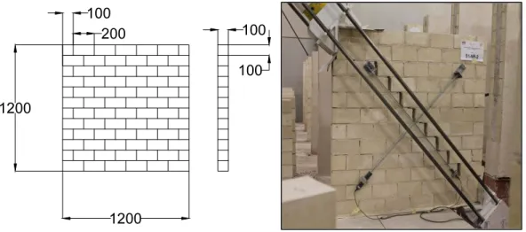
Fig. 13 - Dimensions of specimens (mm) and failure of URM wall © ... 42
Fig. 14 - Pietra leccese walls. Damage pattern for: (a) 15 cm thickness and mortar 8 MPa compressive strength; (b) 10 cm thickness and mortar 8 MPa compressive strength; (c) 10 cm thickness and mortar 13 MPa compressive strength ©. ... 44
Fig. 15 – Fiber grid failure: (a) rupture, (b) sliding©. ... 47
Fig. 16 - Un-reinforced masonry. Experimental vs. analytical - laboratory stone masonry test, [19]. ... 50
Fig. 17 - Un-reinforced masonry. Experimental vs. analytical - in-situ stone masonry test, [18]. ... 50
“Analytical model for shear capacity of masonry retrofitted with fiber reinforced mortar layer”
Erasmus Mundus Programme ADVANCED MASTERS IN STRUCTURAL ANALYSIS OF MONUMENTS AND HISTORICAL CONSTRUCTIONS xx
Fig. 18 - Un-reinforced masonry. Experimental vs. analytical - laboratory brick masonry test, ... 50
Fig. 19 - Un-reinforced masonry. Experimental vs. analytical - pietra leccese test, [26]. .... 51
Fig. 20 - Un-reinforced masonry approach. Experimental vs. analytical – masonry +
reinforcement. ... 52
Fig. 21 - Un-reinforced masonry approach. Experimental vs. analytical, masonry + mortar + reinforcement. ... 53
Fig. 22 - Data Mining Model - α forecast: actual vs. predicted. ... 57 Fig. 23 - Data Mining range check. ... 59 Fig. 24 - Reinforced masonry approach. Experimental vs. analytical - (masonry + mortar) +
reinforcement. ... 61 Fig. 25 - Un-reinforced masonry approach (triangle) vs. Reinforced masonry approach
(circle). ... 62 Fig. 26 - Data Mining Model Validation. Experimental vs. analytical. ... 63
“Analytical model for shear capacity of masonry retrofitted with fiber reinforced mortar layer”
Erasmus Mundus Programme
ADVANCED MASTERS IN STRUCTURAL ANALYSIS OF MONUMENTS AND HISTORICAL CONSTRUCTIONS xxi
TABLES LIST
Table 1 - Nominal shear strength provided by the masonry in the un-reinforced masonry approach. ... 24 Table 2 - Nominal shear strength provided by the masonry in the reinforced masonry
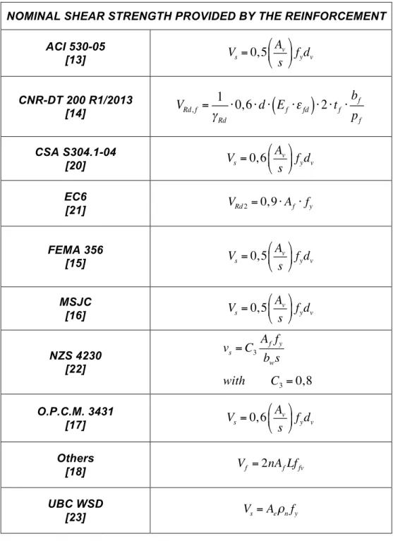
approach. ... 25 Table 3 - Nominal shear strength provided by the reinforcement (carbon or glass fibers) in
the reinforced masonry approach. ... 26 Table 4 - Infill wall. Summary of the equivalent single-strut models. ... 45
Table 5 - Infill wall. Summary of the equivalent multiple-strut models. ... 46 Table 6 - Literature data report. ... 48
Table 7 - Un-reinforced masonry. Experimental vs. analytical results. ... 51
Table 8 - Data Mining Database. ... 56
Table 9 - Data Mining Model Output. ... 58
Table 10 - Data Mining range check. ... 60
Table 11 - Masonry shear capacity increase ... 62
Table 12 - Data Mining Model Output. ... 64 Table 13 - Data Mining - Model n°1 ... 80
Table 14 - Data Mining - Model n°2 ... 80 Table 15 - Data Mining - Model n°3 ... 81
Table 16 - Data Mining - Model n°4 ... 81 Table 17 - Data Mining - Model n°5 ... 82
Table 18 - Data Mining - Model n°6 ... 82 Table 19 - Data Mining - Model n°7 ... 83 Table 20 - Data Mining - Model n°8 ... 83 Table 21 - Data Mining - Model n°9 ... 84
“Analytical model for shear capacity of masonry retrofitted with fiber reinforced mortar layer”
Erasmus Mundus Programme ADVANCED MASTERS IN STRUCTURAL ANALYSIS OF MONUMENTS AND HISTORICAL CONSTRUCTIONS xxii
Table 22 - Data Mining - Model n°10 ... 84
“Analytical model for shear capacity of masonry retrofitted with fiber reinforced mortar layer”
Erasmus Mundus Programme
ADVANCED MASTERS IN STRUCTURAL ANALYSIS OF MONUMENTS AND HISTORICAL CONSTRUCTIONS xxiii
NOTATION
Ae = effective area of masonry, mm2;
Am = interface loading area between steel shoe and wall, mm2
An = cross-section net area of masonry wall, mm2;
Av = cross-section net area of the reinforce, mm2;
α
= factor equal to 0.5 for fixed-free cantilever wall, or equal to 1.0for fixed-fixed pier;
tan
α
= tangent of the angle between the diagonal strut of the wall and the vertical axis of wall, deg.;b = coefficient related to the stress distribution on the
cross-section. It depends on the slenderness of the wall and can be assumed equal height/length and not over 1,5 or under 1,0;
bf = dv = width of FRP strips, mm;
bw = effective width of the wall, mm; © = author copyright;
C1 ; C2
= constants can be obtained from tables provided by the code [22];
Cd = nominal shear strength coefficient;
εfd = fibers design deformation;
d = effective length of the wall and is taken as 0.8lw, mm; Ef = elastic modulus in fibers direction; MPa;
fa = axial compressive stress due to gravity loads, MPa; fb = normalized compressive strength of the units, MPa;
!
“Analytical model for shear capacity of masonry retrofitted with fiber reinforced mortar layer”
Erasmus Mundus Programme ADVANCED MASTERS IN STRUCTURAL ANALYSIS OF MONUMENTS AND HISTORICAL CONSTRUCTIONS xxiv
fmdh = compressive strength in shear direction, parallel to mortar
joints, MPa;
fm = lower bound masonry compressive strength, MPa;
!
fm = specified compressive strength of masonry, MPa;
!
ft = tensile strength of masonry, MPa;
ftd = tensile strength due to diagonal force, MPa;
fvd = shear strength of masonry; MPa;
fvko = shear strength under zero compressive stress; MPa;
fy= ffv = tensile strength of reinforce; MPa;
gb = design load per unit area normal to the bed joint, MPa;
σ0 = average normal stress referred to the total cross-section,
MPa;
σd = design compressive stress normal to the shear stress, MPa;
h = height of brick, mm;
heff = height to resultant of lateral force, mm;
L = length of masonry, mm;
M = maximum moment for the considered section, Nmm; n = number of layers of mesh reinforcement;
N* = axial load, N;
Nv = horizontal component of the diagonal force, N;
θ = inclined angle between horizontal and main diagonal of wall, deg.;
µ0 = coefficient of internal shear friction in mortar joint;
PCE = expected gravity compressive force applied to a wall or pier component considering load combinations, N;
“Analytical model for shear capacity of masonry retrofitted with fiber reinforced mortar layer”
Erasmus Mundus Programme
ADVANCED MASTERS IN STRUCTURAL ANALYSIS OF MONUMENTS AND HISTORICAL CONSTRUCTIONS xxv pf = s = FRP strips distance; mm;
PL = lower bound axial compressive force due to gravity loads, N; t = thickness of masonry, mm;
tf = thickness of the reinforce, mm;
vbm = basic masonry shear strength determined from tables, MPa; vte = average bed-joint shear strength, MPa;
γm = material factor for the masonry;
γRd = partial coefficient related to the resistant model, equal to 1,2;
γg = factor to account for the type of grouting (un-grouted, partially grouted or fully grouted) and is equal to unity for fully grouted walls;
ϕm = resistance factor of masonry;
τ0 = bond strength of the mortar joint, MPa;
τ0d = shear strength of masonry, MPa;
x = neutral axis – external compressed side distance, mm;
V = maximum shear for the considered section, N; Vm = nominal shear strength, N;
w = length of brick, mm;
Chapter 1 -
INTRODUCTION
This thesis contributes a new approach to the problematic of analytical model of the reinforced masonry shear strength prediction. The goal is to provide a complete treatment that consider: masonry structures, mechanic of masonry, experimental tests and analytical model.
In this chapter a brief presentation of the thesis is developed. Layout and contents are described as also motivation and object of the research.
Masonry is one of the most used construction materials having been widely used in building construction over centuries. The walls surround and protect the environment from the weather; also support its own weight, the roofs (slabs and volts) and external loads. The walls are called continuous when the height and
“Analytical model for shear capacity of masonry retrofitted with fiber reinforced mortar layer”
Erasmus Mundus Programme ADVANCED MASTERS IN STRUCTURAL ANALYSIS OF MONUMENTS AND HISTORICAL CONSTRUCTIONS 2
length are much more greater than the thickness and no hollows can be detected on it. It is called isolated when the height prevails over the other two dimensions (pillars and columns). [1]
The walls, from the viewpoint of material, are made of a combination of natural stone or artificially produced bricks and mortar joints, which has the task of creating continuity in the wall and spread out the pressure between the various elements. The outer surfaces are the usually subjected to degradation as they are:
• exposed to different environmental agents;
• exposed in particular to water in all its forms: ice, vapour, liquid;
• made of many porous and non-porous materials. [2]
There are several ways for a load-bearing wall to collapse an entire building. Normally, the walls are compressed. When the load it supports exceeds its strength it has reached the limit for compression stress state (and consequently it cracks due to crushing). It happens differently depending on:
• concentrated loads;
• distributed loads.
The vertical loads do not always generate pure compression stresses as, for example, at an opening. or when they are not "centred" in the section (eccentricity), or even when the masonry cannot find (or loses) a support; the result is a production of tensile stresses in some sections. In these cases it is possible that the wall reaches the limit of its tensile strength.[1]
In order to counteract the expansion of the masonry element in the tensile state stress different solutions have been developed. A general distinction of consolidation techniques can be done based on where they take place like:
• inside;
Chapter 1 - INTRODUCTION
Erasmus Mundus Programme
ADVANCED MASTERS IN STRUCTURAL ANALYSIS OF MONUMENTS AND HISTORICAL CONSTRUCTIONS 3
Inside techniques consider all the interventions used to increase the density of the masonry by injection materials like semi-liquid mortar or resins. Or also, to produce holes and insert steel bars or cables reinforcement. As a result, in-plane and out-of-plane capacity is increased. Outside techniques consider addition of material on the surface by adhesion or connectors. Most used materials are steel grid and plaster. [2]
The present work of this thesis focuses attention on the external reinforcement technique of reinforce plaster and provides an analytical model able to predict the behaviour of retrofitted masonry. The challenge is to realise a model that simplifies the complex behaviour of an element made of three layers with different characteristics.
1.1 Research motivations and objectives
The analysis of masonry panels retrofitted with Fiber Reinforced Polymers (FRPs) has been the subject of many studies. On the other hand, prediction of the actual ultimate capacity requires specialized analysis which is often complicated to understand or to use. Modern codes and standards are introducing the need to perform limit state analysis. The current study aims to provide an innovative analytical model for the masonry panels retrofitted with reinforced plaster made of advanced materials. The use of fiber grids and cement mortar is becoming popular materials for retrofitting the masonry walls. The reinforcement technique considered in this study consists of the application of a mortar reinforced with GFRP network on both faces of the masonry and anchored to the masonry surface by means of suitable connection devices.
This study will also present deep knowledge in masonry behaviour and a summary of the literature approach to this problem. The motivation in principally to provide a useful tool for the engineering designers.
“Analytical model for shear capacity of masonry retrofitted with fiber reinforced mortar layer”
Erasmus Mundus Programme ADVANCED MASTERS IN STRUCTURAL ANALYSIS OF MONUMENTS AND HISTORICAL CONSTRUCTIONS 4
1.2 Outline of the thesis
The current study is presented in four chapters, of which this introductory section constitutes the first chapter.
Chapter 2 reports a survey of the applicable literature. In the introduction part, a brief historical overview of the origin and evolution of masonry structures and a description of the analytical model concepts are provided. In particular, it also explains the changes in the behaviour of masonry after retrofitting with the reinforced plaster. Common tests for shear capacity estimations are also reported following current standards and recommendations. Useful formulas are collected from some available codes and publications. This chapter ends with a description of the Data Mining technique which is used later for optimization of the proposed model.
Chapter 3 explains the experimental procedures used to achieve the research objectives. The purpose and design of the devices employed are explained as well as the procedures for conducting the various required tests. Experimental data are reported for each specimen and specimen group. Two different analytical models are proposed (one consists of existing improvement and other is from the Data Mining analysis). The models are compared with available experimental database and validations are presented. It ends with the display of the results of each experimental test. It also presents a summary of the results of the two analytical models and provides a comparison of their results.
The main conclusions of the case study as well as recommendations are presented in chapter 4 and finally, expose future challenges for the final version of Data Mining model.
Chapter 2 -
LITERATURE REVIEW
This chapter aims to review literature related to the present study in eight sections with the intension to clarify the motivations and aspirations of the entire thesis. Section one summarizes briefly the history line of masonry structures. Section two describes what is a model, hot to built it and why it is important in engineering field. Section three lists the masonry behaviour of masonry under compression action; load considered in treatment of chapter 3. Section four offerings a description of the reinforced plaster technique; object of the challenge of the model proposal in this thesis. Section five grants a discussion about in-plane shear response of masonry with particular attention to the behaviour of reinforced and un-reinforced panels. Section six presents a review of previous researches on
“Analytical model for shear capacity of masonry retrofitted with fiber reinforced mortar layer”
Erasmus Mundus Programme ADVANCED MASTERS IN STRUCTURAL ANALYSIS OF MONUMENTS AND HISTORICAL CONSTRUCTIONS 6
masonry shear strength model and summarized the principal standards for common shear tests performed on masonry panels. Section seven figures out the analytical model for un-reinforced and reinforced masonry shear capacity provided by Codes and Standards. In the last section data mining processes is defined.
It is fundamental to understand the importance and the advantages that masonry construction guarantee and which are the points of weakness of this material. Speed of erection is one of the main advantages of masonry construction. A masonry wall can easily be built, and supports a floor load soon after that. In comparison, an in-situ reinforced concrete column where the time taken to fix the reinforcement, erect shuttering, cast concrete, cure, prop, hardening and then strike the shutter is often more time consuming. It is generally recognised the aesthetics value of masonry structures with respect to steel, timber and especially concrete buildings. The excellent durability of masonry is obviously a great advantage. Many historic buildings and engineering structures provide living proof of this quality. [2]
Acoustic insulation of structures is of critical importance in the building comfort. One of the traditional solutions to this issue is structural mass – the heavier the partition, the less the noise can be transmitted through it. The good thermal properties of cavity walls have long been recognised and, more recently, have become critical in the attempts to conserve energy. Cavity walls and diaphragm walls can easily be insulated within the void to provide further improved thermal proprieties. Bricks are not combustible and could not start or spread a fire. Masonry is rarely seriously damaged in fire; it does not buckle like steel, spall like reinforced concrete or burn like timber. [1]
It is essential when using masonry not to use a strong mortar, relative to the strength of the brick or block. The mortar joints should always be the weak link, in order to retain any cracking within the numerous bed and perpendicular joints between bricks or blocks. A correct relationship between the mortar and the brick or block strengths results in global distribution of the deformation among numerous fine cracks. This propriety provides resistance to movement. Masonry units can be
Chapter 2 - LITERATURE REVIEW
Erasmus Mundus Programme
ADVANCED MASTERS IN STRUCTURAL ANALYSIS OF MONUMENTS AND HISTORICAL CONSTRUCTIONS 7
recycled for future use in new construction, or crushed and used for hardcore/fill material in new construction. [3]
The many uses to which masonry can be put, the wide range of materials and material behaviour, and the great strides forward in the structural use of masonry, require a sound understanding of this material to prevent misuse and ensure an economical and efficient design and construction. Unfortunately, education has been lagging behind developments, and this has left the construction industry in a situation where it cannot fully exploit masonry’s capabilities until it is geared up to the techniques and applications. [3]
In situations where large openings are to be formed and a level soffit is required, reinforced concrete or steel beams are generally found to be the most economical means of support. They can be combined with the composite action of any masonry above and unless fair-faced masonry is a particular requirement for the soffit of the support, they usually provide a more economical solution than the masonry alternative. It must be pointed out, however, that where the soffit can be in the form of an arch, and where the horizontal reactions from such a form can be accommodated, masonry may prove more economical. [1]
In some forms of masonry construction, there is a need for relatively close spacing of the control joints to prevent shrinkage and/or expansion cracking due to structural, visual and other constraints. It should be remembered, however, that masonry is often required for partition walls when an independent structure is employed, and the introduction of a frame in a different material can often cause an even greater problem from differential movements. [3]
2.1 Milestones of masonry structure
Analyse the history is essential to cognize the nowadays scenario. The necessity of studying and better understanding the complex behaviour of ancient structures, before performing any kind of interventions, has convinced engineers and academics in general. The goal is to know the history of the buildings, in order to operate effectively in the present and to preserve the ancient buildings for the
“Analytical model for shear capacity of masonry retrofitted with fiber reinforced mortar layer”
Erasmus Mundus Programme ADVANCED MASTERS IN STRUCTURAL ANALYSIS OF MONUMENTS AND HISTORICAL CONSTRUCTIONS 8
future. The use of stone for building proposes is one of the most ancient conquests of humanity. Primitives looked for shelter in the natural caves and slowly started to adapt to their necessity through a rational use of the spaces. The masonry has been developed in a continuous way after the advent of the great urban civilizations and marks the transition from construction techniques related to wood, straw, hides, etc. to a new age of more durable and solid buildings. Initially the bearing walls were made dry, simply by placing natural stones one on other, trying to fix them as best possible, to guarantee a good stability and bearing capacity. Examples of this practise are the famous “Trulli” (Fig. 1); structures typical of Apulia region in Italy present also in the Word Heritage UNESCO List. [4]
Fig. 1 - Trulli of Alberobello, Apúlia, 2011 ©.
With the development of techniques and technologies, stone was used and dry walls were realized. The wall of hewn stone is very durable and very stable, but it is more complex to implement. At the same time as the development of the hewn stone walls, the techniques of building brick wall was developing. Initially it used simple brick mold with earth and straw, dried in the sun. Firing clay at high temperatures means that the brick hardens considerably and gains strength, a construction technique that has been adopted continues today. One of the most famous examples is the great “Mosque of Djenné” (Fig. 2), which is one of the biggest adobe structures in the world. [2]
Chapter 2 - LITERATURE REVIEW
Erasmus Mundus Programme
ADVANCED MASTERS IN STRUCTURAL ANALYSIS OF MONUMENTS AND HISTORICAL CONSTRUCTIONS 9
Fig. 2 - Mosque of Djenné, Mali (source: Google Pictures).
With the discovery of lime, masonry underwent the last major technical break through in its evolution and was born on the wall bedridden with lime. This technique consists of positioning the bricks on one another, taking care to discard a layer of lime on the bottom row of bricks, and between a brick and another in the same row.
The lime hardens, it binds to the baked bricks (which have a rough surface that favours the socket) and with them creates a single structural element much more resistant than adobe. Regarding the strength, durability and overall quality, the walls made of large squared stones, remained the best possible solution, and was used throughout the classical period and in the Gothic period for the construction of buildings of greater value. [1]
The discovery of iron and steel first, and then concrete, led to the major decline of the stones walls in favour of brick walls set with lime mortar or cement mortar. Currently the bearing walls are made of bricks of clay solid or perforated, or with bricks of many other materials, including cement (more properly concrete) and its derivatives (Fig. 3). [2]
“Analytical model for shear capacity of masonry retrofitted with fiber reinforced mortar layer”
Erasmus Mundus Programme ADVANCED MASTERS IN STRUCTURAL ANALYSIS OF MONUMENTS AND HISTORICAL CONSTRUCTIONS 10
Fig. 3 - Lime mortar masonry (source: Google Pictures).
Interventions of consolidation for stone materials must restore continuity which has been altered because of different phenomena. The consolidation operation must, in fact, ensure structural solidarity behaviour. The goal is to restore the original strength of the healthy material avoiding, excessive intervention that could alter the intrinsic constitution of the structure causing long-term effects difficult to predict. [2]
The intervention of the consolidation of a wall unit is particularly complex. It is significantly affected by the knowledge of several factors including: the nature of the materials, the changes due to the natural aging of the structure, the various diseases of degradation present, the state of preservation and the stresses in place. Defineding the cognitive framework of the structure is important to establish whether it is really possible to eliminate the causes that have resulted in degenerative diseases; contrary to the intervention of consolidation that can not be considered decisive and long-lasting. [2]
In this section line history of masonry structures was presented in order to exhibit the possible fields of application of the model object of the thesis.
Chapter 2 - LITERATURE REVIEW
Erasmus Mundus Programme
ADVANCED MASTERS IN STRUCTURAL ANALYSIS OF MONUMENTS AND HISTORICAL CONSTRUCTIONS 11
2.2 What is a model
Nowadays, analytical and numerical modelling has become an essential tool in most of the science branches, included Engineering science. This methodology usually consists of four steps. The first step is the design of a mathematical procedure corresponding to the physical problem with appropriate assumptions or simplifications of the reality. [5]
This procedure may take the form of differential or algebraic equations. In most cases, these mathematical models cannot be solved analytically and require numerical solution. The second step is development of a numerical model or approximation to the mathematical model. The numerical model usually needs to be carefully calibrated and validated by existing data. Error analysis of the numerical model is also required in this step. The third step of theoretical modeling is actual implementation of the numerical model to obtain solutions. The fourth step is interpretation and presentation of the numerical results in the form of graphs or tables and validation of the initial assumptions. [6]
The modeller ensures through qualitative understanding of the phenomena that the mathematical equations and their numerical result, coming out of the proposal procedure, reflect reality. It is fundamental to identify the involved variables and their interaction in order to realize an acceptable description of the phenomena.[5]
Analytical models do not eliminate the indispensable experimental approach that provides observations of actual physical phenomena. Many theoretical and empirical models are based on the interpretation of experimental results because they are useful in order to validate the theoretical hypotheses. Models make it possible to:
• identify the relationships between cause and effect. This leads to a deeper understanding of the problem at hand by deriving an analytical relationship between them;
“Analytical model for shear capacity of masonry retrofitted with fiber reinforced mortar layer”
Erasmus Mundus Programme ADVANCED MASTERS IN STRUCTURAL ANALYSIS OF MONUMENTS AND HISTORICAL CONSTRUCTIONS 12
• predict how the respective objects can expect to perform over a finite future time span, but also to experiment with models. The ability to make predictions about the future forms the core of intelligence;
• simulate the objects' behaviour by experimenting with models, and thus answer "what-if" questions essential to decision-making;
• control the objects by finding suitable means to affect the objects and enforce a specific behaviour. [6]
In this section what is an analytical model and why it is considered a powerful tool for engineers is defined.
2.3 General aspects of masonry
In recent decades, the interest for masonry structures has greatly increased specially for problems associated with the consolidation and preservation of the existing structures. Particular incentive for studying of masonry has been the series of earthquakes that happened in the last century particularly in the Mediterranean area causing damage and often the collapse of many monuments and buildings. [1]
There are not only the catastrophic events that cause damage of masonry structures, but also the accumulation of damage over time, due to various factors such as traffic vibrations, wind, thermal loads, the ground motions: causing degradation of the strength of the material and threatening our architectural heritage. The importance of studying masonry and its behaviour under the action of loads was born from those considerations. [1]
Masonry consists of units connected together by continuous horizontal and discontinuous vertical mortar joints, each component can be various in nature and can be assembled in many different ways. The term "masonry" thus embodies a considerable amount of building types with different materials, texture and size of the blocks. [3]
Chapter 2 - LITERATURE REVIEW
Erasmus Mundus Programme
ADVANCED MASTERS IN STRUCTURAL ANALYSIS OF MONUMENTS AND HISTORICAL CONSTRUCTIONS 13
The components, units and mortar, affect the overall behaviour: the masonry has distinct directional properties, mainly due to the horizontal mortar joints that are real planes of weakness. [1]
A wall construction is an assembly, by ordered overlapping, of stone elements and/or clay bricks arranged to obtain a complex structure with certain stability. Moreover, it is a composite material whose constituent elements (mortar and brick or stone) have mechanical properties very different from each other. It is reasonable to expect that the characteristics of the masonry are intermediate between those of its constituents as shown in Fig. 4. [7]
Fig. 4 - Stress-strain behaviour of brick, mortar and masonry [7]
The principal mechanical characteristics of masonry are:
• Inhomogeneity; • Asymmetry; • Anisotropy;
• Non-linearity of the stress-strain behaviour.
It is inhomogeneous because the blocks and the mortar often have strongly different mechanical properties. However, knowing the mechanical properties of the individual components are often not sufficient in order to predict the global
“Analytical model for shear capacity of masonry retrofitted with fiber reinforced mortar layer”
Erasmus Mundus Programme ADVANCED MASTERS IN STRUCTURAL ANALYSIS OF MONUMENTS AND HISTORICAL CONSTRUCTIONS 14
behaviour. The main role, in fact, is performed by the interaction of the components that is not necessary close to the behaviour of one of the components. The macroscopic behaviour of masonry is a complex phenomena resulting from the cooperation at the contact surface of brick and mortar. [7]
It has asymmetric mechanical behaviour due to the not symmetric behaviour of its components and due to the fact that the tensile strength of the mortar-brick contact is generally lower than the masonry unit. Based on this consideration, masonry is often modelled as a no tensile strength material. [7]
It is anisotropic because the shape and the proportion of the bricks and how they are allocated in the masonry texture, affect the structural response. There are also uncertainties due to the possible presence of holes or voids that should not be neglected. Most masonry wall configurations present regularity in the horizontal direction contrary to the vertical direction due to the misaligned vertical mortar joints. Moreover, the strength depends not only on the applied loads but also their direction. Experimental evidences of mono-axial tensile and compressive tests are:
• Both constituents have lower tensile strength with respect the compressive strength;
• Brick has higher tensile strength and Modulus of elasticity than the mortar; • Mortar has a large deformation range with respect to the brick. Moreover
it has ductile behaviour differently from the brick that is fragile. [7]
A typical tensile-compressive test on masonry (Fig. 5) indicate the following chracteristics:
• OA linear tract of modest extension;
• AB not linear tract due to the cracks formation;
• point B corresponding to the maximum compressive stress;
Chapter 2 - LITERATURE REVIEW
Erasmus Mundus Programme
ADVANCED MASTERS IN STRUCTURAL ANALYSIS OF MONUMENTS AND HISTORICAL CONSTRUCTIONS 15
• point C corresponding to masonry crushing failure; • short OI linear tract in tension;
• point I corresponding to maximum tensile stress; • short IL tract for decreasing stresses. [7]
Fig. 5 - Experimental stress-strain chart for masonry [7].
One of the most precise and adopted models to describe the masonry behaviour is the “elastic not-linear model”. It approximates well the OAB path (Fig. 5) with a not-linear function that interpolates the experimental points. This model is preferable to the linear model because it better approximates the real behaviour. It is also useful for the numerical analysis because it may take into account the limited tensile strength. However, it has the disadvantage of not considering the plastic deformation and therefore cannot be used for cyclic loading conditions. The compressive strength of masonry (orthogonal to the joints) is affected by the strength, the geometry and deformability of the components; by the joints thickness, presence of water (due to the brick absorption and release to the mortar) and the chosen texture. The compressive failure appears with propagation of vertical cracks
“Analytical model for shear capacity of masonry retrofitted with fiber reinforced mortar layer”
Erasmus Mundus Programme ADVANCED MASTERS IN STRUCTURAL ANALYSIS OF MONUMENTS AND HISTORICAL CONSTRUCTIONS 16
in the components due to the principal tensile stresses, orthogonally oriented with respect to the compressive principal stresses. [8]
The tensile strength is caused by the interaction of mortar and bricks mechanical incompatibility which results in different deformation. The major deformability of the mortar induces high expansion of the mortar joint. This possibility is constrained by the friction stresses present at the interface level. As a result, there is a tri-axial compressive stress state in the mortar and tensile stresses in the brick. For this reason the masonry can support higher compressive stress than the mono-axial mortar strength. [8]
The compressive strength of masonry increases if the strength of the components increases, but not proportionally. Using high strength mortar leads to significantly increasing the masonry strength but this benefit is lower if the brick strength is increased. It is important to note that the masonry compressive strength decreases if the joint thickness increases (much more If the mortar is poor). [2]
In this section masonry id analysed from the material point of view. In particular compression e tensile response is presented. This characteristics will be useful in next chapter for the masonry shear strength prediction using formulas provided in scientific publications.
2.4 Reinforced plaster
The consolidation or strengthening of masonry wall subject to horizontal in-plane force like dynamic actions (earthquake, wind, etc.) in addition to its own weight, is very important to reach an acceptable security level. The weakness of the masonry mechanical characteristics (resistance to compression, shear, etc.) is well known and it is often the cause of collapse or serious damage in historic buildings, for example during seismic events. [1]
Various techniques are currently used for the reinforcement of masonry constructions. The main focus of this thesis is application of reinforced plaster layer on the wall’s surface (Fig. 6). Also known as plating, this technique consists of applying a layer of mortar (cement mix to fine particle size) with a minimum
Chapter 2 - LITERATURE REVIEW
Erasmus Mundus Programme
ADVANCED MASTERS IN STRUCTURAL ANALYSIS OF MONUMENTS AND HISTORICAL CONSTRUCTIONS 17
thickness of 4 ÷ 5 cm reinforced with welded mesh, on both faces of the wall to be consolidated. The two layers are also connected together by metal brackets inserted passed through the wall’s thickness. [9]
The technique has the disadvantage of increasing, even if only slightly, the thickness of the wall and is not applicable in cases in which the view of the rustic wall is to be preserved. It proceeds first by removing the existing plaster and then drilling specific holes in which the connecting brackets will be passed through (at least 6 per square meter); after having placed the welded mesh, the wall is wetted followed by spraying a dry mixture consisting of one part cement and four sand, and water. The result is the realization of two small reinforced concrete walls interconnected by metal connectors. [3]
This technique is often used to reinforce irregular and poor quality walls. It has a high mechanical efficiency, but it is very invasive: the inner wall is, in fact, "lost" not only because it is not visible, but also because it is subjected to rapid deterioration mostly because moisture cannot pass from side to side anymore as governed by the natural osmosis phenomena. Another disadvantage is that the new wall panel provides, with respect to the original, a much higher stiffness that can compromise the original behaviour of the building with negative implications on the structural behaviour. [9]
“Analytical model for shear capacity of masonry retrofitted with fiber reinforced mortar layer”
Erasmus Mundus Programme ADVANCED MASTERS IN STRUCTURAL ANALYSIS OF MONUMENTS AND HISTORICAL CONSTRUCTIONS 18
In this section the masonry reinforcement technique that the author proposes to model is accessible. Knowledge of the technique is fundamental for the understanding of the physical phenomenon that is observed when the so-reinforced masonry is solicited by shear actions in the plan.
2.5 In-plane shear response of masonry
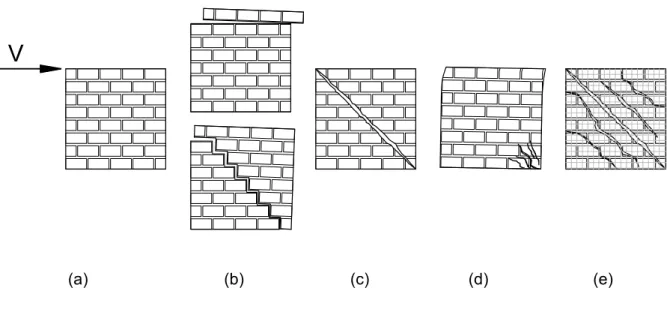
A shear wall’s capacity derives from a high moment of inertia about one axis, high compressive strength brickwork, and bond joint tensile capacity. The accurate prediction of lateral load capacity of URM walls is difficult because of the complex brick-mortar interaction behaviour. The masonry units can be stone, calcium silicate, clay or concrete. The present thesis work deals with stone unit. The main in-plane failure mechanisms of URM walls subjected to in-plane shear actions are summarized in Fig. 7. [9]
(a) (b) (c) (d) (e)
Fig. 7 - Masonry shear failure modes: (a) original masonry; (b) sliding; (c) diagonal crack; (d) toe crushing; (e) diagonal cracks in grid reinforced masonry ©.
Sliding failure mode.is typical in cases that low vertical loads and/or low friction coefficient, which may be due to poor quality mortar, exist. The cracks are therefore formed at the bed joints followed by sliding the upper part of the wall at the crack surface. These cracks can follow the horizontal or the stair-stepped direction
Chapter 2 - LITERATURE REVIEW
Erasmus Mundus Programme
ADVANCED MASTERS IN STRUCTURAL ANALYSIS OF MONUMENTS AND HISTORICAL CONSTRUCTIONS 19
thought the vertical and horizontal joints depending on the mechanical properties of the mortar and the brick. The fault is attributed to the shear bond capacity of the mortar-brick contact; in fact, cracks in the bricks do not appear. [10]
In diagonal shear mode, the failure occurs when the principal tension stress induced by a combination of higher shear and compressive force reaches the tensile strength of the wall. Diagonal cracks develop in the wall both in mortar and brick. A wall fails by toe crushing when the generated stresses reach the masonry compressive masonry strength. In this case, cracks appear in compressed zones at the edge of the wall. [10]
The use of FRP composites for retrofitting of masonry structures offers various advantages like the low size and weight which the wall does not significantly change. From the architectural point of view, the application of FRP composites has aesthetic impact but it is considered reversible in most cases. It should be noted, however, that the durability and compatibility of FRP with the masonry substrate in various moisture and temperature condition represents a limit. Nowadays, the benefit of this technique is well known and it mainly increases of the load-carrying capacity and ductility of the system, and generates a uniform distribution of cracks. The possible failure modes of the FRP reinforced wall are: debonding of the FRP laminate from the masonry substrate; splitting of masonry and sliding shear along a mortar joint. [11]
If the V force (shear action) is not horizontal but, directed along the diagonal, failure modes illustrated in Fig. 7 (c), (d) and (e) may occur. Sliding failure (b) can occur only in stair-stepped direction and not through an entire horizontal joint. [9]
In this section masonry shear response is pointed. In particular the different behaviour of un-reinforced and reinforced masonry is explained. This is a crucial section because it affect the next chapter where two different model will be provided in order to cover the reinforced masonry shear strength as in the case it shows un-reinforced masonry behaviour (Fig. 7 b, c and d) as un-reinforced masonry behavior (Fig. 7 e).
“Analytical model for shear capacity of masonry retrofitted with fiber reinforced mortar layer”
Erasmus Mundus Programme ADVANCED MASTERS IN STRUCTURAL ANALYSIS OF MONUMENTS AND HISTORICAL CONSTRUCTIONS 20
2.6 Diagonal compressive test and horizontal compressive test
Extensive experimental and theoretical studies have been carried out to report the shear behaviour of masonry walls since the 1960’s. In-plane shear strength is a basic mechanical characteristic of masonry walls and can be defined as the resistance of the wall to lateral in-plane loads when the wall fails in shear.
The diagonal compression test is a destructive test that is performed on a wall in order to determine the shear stiffness. The reference standard for the execution of this test is ASTM E 519-81 "Standard Test Method for Diagonal Tension (Shear) in Masonry Assemblages" [12]. The code specified procedure for determination of the tensile or shear strength of diagonal panels masonry is to diagonally load the panel under compressive loads up to the failure. The extension of ASTM E 519-81, for in-situ testing involves the isolation of a square panel of dimensions 120 x 120 cm (thickness varying between 25 and 70 cm) from the surrounding wall by means of four cuts made in so as to disturb as little as possible to the wall panel to be tested (diamond wire saw, circular saw, chainsaw, etc.). To ensure the stability of the panel, it is necessary to keep the panel clamped to the wall by limiting the lower cut square test: this circumstance differs from the test in situ laboratory testing, however, theoretical and numerical analysis proved that the scarfing, at least in the elastic phases influences the results in negligible way.
In order to apply the load, a system constituted by suitable metal elements (steel shoes) arranged along the two edges of the diagonal of the free wall panel (one end of the other is still fixed to the masonry) and connected between them should be built. In one of the two edges the hydraulic thrust system is positioned which acts between two steel shoes. The inner one is leaning against the edge of the panel and the external connected by steel bars placed on the steel shoe on the opposite edge to the first (Fig. 8). Through this closed system, the load is transmitted to the panel along a diagonal. The deformation of the panel is monitored by means of two pairs of transducers, one for each face, arranged along the diagonals. During the test, for each load step, the diagonal Fd and the variations of
Chapter 2 - LITERATURE REVIEW
Erasmus Mundus Programme
ADVANCED MASTERS IN STRUCTURAL ANALYSIS OF MONUMENTS AND HISTORICAL CONSTRUCTIONS 21
test, together with the geometrical dimensions of the actual wall panel tested, allow determination of the diagonal shear behaviour of the masonry. The test can also be performed by rotation of the specimens to of 45° (Fig. 8 b). [12]
(a) (b)
Fig. 8 - Layout of the diagonal compression test on panel wall: (a) 0°, (b) 45° inclination ©.
This type of test is not without critics. In fact, the concentrated diagonal load creates a complex tensional state such that only the central part of the panel has a reasonably uniform state of biaxial tension. The nominal value of τ related to the horizontal component of the load Fd is equal to:
𝑎
τ =0, 707 ⋅ Fd,max
An
“Analytical model for shear capacity of masonry retrofitted with fiber reinforced mortar layer”
Erasmus Mundus Programme ADVANCED MASTERS IN STRUCTURAL ANALYSIS OF MONUMENTS AND HISTORICAL CONSTRUCTIONS 22
The experimental data obtained from this type of test provides average values due to the influence of geometry and the size effect. Despite this, this kind of test can be considered valid in order to estimate masonry shear capacity fck 0 in absence of compressive loads as:
fvko= 0, 7τ (2)
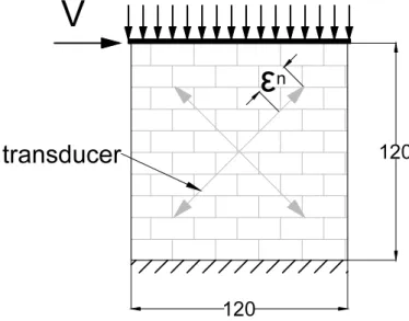
Masonry shear capacity can also be obtained from an horizontal load test but (not for the present work of thesis). The test scheme allows obtaining information on the global behaviour of the panel under shear action (Fig. 9). [12]
Fig. 9 - Horizontal compressive test ©.
Its resistance (due to the horizontal shear loading) is determined using the Coulomb criteria, well known in soil mechanic fields. The average value of the ultimate shear stress fvu in the horizontal section of the masonry can be expressed with the relation present in the Eurocode 6 [14]:

![Fig. 4 - Stress-strain behaviour of brick, mortar and masonry [7]](https://thumb-eu.123doks.com/thumbv2/123dok_br/17704964.828665/41.892.242.678.455.758/fig-stress-strain-behaviour-brick-mortar-masonry.webp)
![Fig. 6 - Reinforced plaster technique [3].](https://thumb-eu.123doks.com/thumbv2/123dok_br/17704964.828665/45.892.221.704.779.1055/fig-reinforced-plaster-technique.webp)

![Fig. 10 - KDD process layout [17].](https://thumb-eu.123doks.com/thumbv2/123dok_br/17704964.828665/61.892.141.799.724.965/fig-kdd-process-layout.webp)