S P E C I A L
Manuel Braz-César · Rui Barros
Optimal control of a plan asymmetric structure using
magnetorheological dampers
Received: 29 March 2016 / Accepted: 12 October 2016 / Published online: 22 October 2016 © Springer-Verlag Berlin Heidelberg 2016
Abstract Although building structures can be perceived as a combination of primary frames in two orthogonal directions, they are three-dimensional systems that usually present a very complex dynamic behavior due to irregular geometric configurations, in particular due to plant stiffness or mass eccentricities. This asymmetric geometry results in coupled lateral–torsional motion produced by wind and seismic loading with consequences in the design of lateral and corner columns. A considerable amount of research effort has been devoted to develop structural control systems to reduce the effects of plan asymmetries and to improve the dynamic behavior of these buildings. This paper presents a numerical analysis of a semi-active control system with MR dampers designed to reduce lateral–torsional responses of a plan asymmetric building structure excited byEl CentroNS earthquake ground motion. A parametric study comprising passive and semi-active control modes is given to demonstrate the effectiveness of the proposed control system with respect to uncontrolled case. The numerical results prove the efficiency of the semi-active control system and its potential use in mitigating coupled lateral–torsional structural responses.
Keywords Structural control·Asymmetric structures·Semi-active control·MR dampers
1 Introduction
Simplified methods for seismic design of buildings are usually based on the lateral motion of the structural system, assuming that it can be modeled by frames in two orthogonal directions. The torsional component can be introduced in the design process using the rigid diaphragm approach in which floor diaphragms are assumed rigid in their own plane to obtain a more accurate representation of the seismic response. However, building structures are complex systems that typically present plan and/or elevation asymmetries as a result of irregular stiffness, strength and/or mass distribution. For instance, plan asymmetries generate correlated plan translations and rotations that lead to an irregular deformation distribution demand among resisting planes namely at the corner columns. As a consequence, there is an increase in force and ductility demand leading to different damage in these elements that generates structural systems with uneven distribution of strength with a large resistant capacity in some load-resisting planes. It should be noted that nowadays, the availability of powerful computational tools has made possible to model complex three-dimensional structures to include combined lateral–torsional motion with high degree of accuracy.
M. Braz-César (
B
)Polytechnic Institute of Bragança, ESTiG, Gab 104, Campus de Santa Apólonia, 5300-253 Bragança, Portugal E-mail: [email protected]
R. Barros
The complex response of irregular building structures can be significantly attenuated using a wise distrib-ution of the structural elements and/or properties that can be modified through the height of the structure in a stepwise fashion at prescribed story levels. Another possible approach is to use control systems to reduce the effects of coupled lateral–torsional motion due to wind or earthquake loading. In fact, a considerable amount of research effort has been devoted over the last 20 years on developing smart control systems for vibration reduction of structures, in particular simplified structural systems with regular geometry. It has been shown that supplemental energy dissipation systems represent an effective approach to reducing the magnitude of both plan translations and rotations in irregular building structures [1–6]. The performance of these control systems can be considerably improved using active or semi-active actuators which can deal with structural nonlineari-ties, variations in the dynamic loading and modifications of the properties of structural elements. Among the different vibration control technology available, magnetorheological (MR) fluid-based devices seem to have the suitable features to develop simple, efficient and cost-effective semi-active control systems for vibration mitigation in civil structures. MR fluids are essentially non-colloidal suspensions of micro-sized magnetisable particles in an inert base fluid along with some additives. The yield strength of MR fluids can be directly modi-fied in the presence of a magnetic field making them particularly adequate to develop control devices in which controlled fluid motion is required such as smart dampers. Thus, MR dampers present a variable damping with the ability to transmit force in a controlled manner in accordance with a prescribed magnetic field, improving their energy dissipation performance compared with traditional dampers. This constitutes an important feature to develop enhanced control systems for many engineering applications, such as the dynamic response of both regular and irregular building structures. In this regard, several studies had already been conducted to investigate the effectiveness of these semi-active actuators to control lateral–torsional coupled responses of asymmetric building structures [7–9].
This paper is devoted to evaluate the effectiveness of MR dampers to mitigate the combined lateral–torsional response of a three-dimensional asymmetric-plan structure under seismic excitation.
The numerical formulation and the dynamic behavior of irregular building structures are initially addressed. The principle of operation of a semi-active control system with MR dampers for a two-story, one-bay building structure with one-way asymmetric structural plan under an unidirectional earthquake ground motion is also presented. In this case, two MR dampers installed between the base and the first floor with a symmetric distribution with respect to the earthquake loading direction are used in passive and semi-active control modes. Numerical simulations are carried out to evaluate the effectiveness of MR dampers in mitigating coupled lateral–torsional motions of the asymmetric building structure. The results for the passive and semi-active configurations are compared with those of the uncontrolled case. Finally, the effectiveness of each control mode is analyzed and evaluated emphasizing the main advantages and limitations of each methodology in controlling the response of the irregular structure. This paper is based upon Braz-César and Barros [10], but the current paper has been enhanced, including new performance criteria to better evaluate the effectiveness of the proposed semi-active control system.
2 Numerical formulation
A two-story three-dimensional building structure subjected to a unidirectional seismic excitation will be used to study the performance of a control system with MR dampers. The schematic representation of the model is shown in Fig.1. In this case, two MR dampers are located at the first floor level, which can be operated in passive and semi-active configurations. The floor diaphragm can be considered rigid in its own plane, and therefore, the dynamic analysis is conducted using a lumped mass model where the whole story mass is lumped at the floor level.
Due to the rigid diaphragm approximation, the response of the structure can be described by three degrees-of-freedom (DOFs) per floor, i.e., two orthogonal translations and a rotation about the vertical axis, resulting in a six DOFs system. Thus, the displacement vector can be expressed as
X(t)= {x1(t),y1(t), θ1(t),x2(t),y2(t), θ2(t)}T (1)
wherexi(t) andyi(t) denotes the displacements of the center of mass of theith floor in thex- andy-directions, respectively, andθi(t) is the vector of rotations of theith floor about the vertical axis. The asymmetric
Fig. 1 Two-story building under unidirectional seismic excitation with two MR dampers
Fig. 2 Floor slab with asymmetric mass distribution
The equation of motion of the building structure subjected to unidirectional earthquake excitation and including the control devices or control forces is given by
MX¨(t)+CX˙(t)+KX(t)= −Mλxg¨ (t)+Ŵf(t) (2)
where M, C and K are the mass, damping and stiffness matrices, respectively. The seismic loadingxg¨ (i.e., in thex-direction) is applied in the structural system using the location vector
λ= {1,0,0,1,0,0}T (3)
The force vector describing the two control forces is given by
f(t)=
fc,1(t),fc,2(t)
T
and the correspondent location matrix can be expressed as Ŵ= ⎡ ⎢ ⎢ ⎢ ⎢ ⎢ ⎣ 1 1 0 0
ly/2 −ly/2
0 0 0 0 0 0 ⎤ ⎥ ⎥ ⎥ ⎥ ⎥ ⎦ (5)
Since the slab has a rigid body motion, the mass matrix represents a lumped system with two masses with mass eccentricitieseyandex =0. Moreover, the additional point mass mahas a negligible rotational inertia,
and therefore, the mass matrix is expressed as
1 1 1
1 1
2
1 1 1
2 2 2
2 2
2
2 2 2
0 0 0 0
0 0 0 0 0
0 0 0 0
M
0 0 0 0
0 0 0 0 0
0 0 0 0
x a a y
y a
a y a y
x a a y
y a
a y a y
m m m e
m m
m e I m e
m m m e
m m
m e I m e
+ − + − + = + − + − + (6)
wheremiandIirepresent the lumped masses and moments of inertia of theith floor, respectively (withi =1, 2). The stiffness matrix is expressed in accordance with the displacement vector as
1 2 2
1 2 2
1 2 2
2 2 2 2 2 2
0 0 0 0
0 0 0 0
0 0 0 0
K
0 0 0 0
0 0 0 0
0 0 0 0
x x x
y y y
x x
y y
K K K
K K K
K K K
K K
K K
K K
θ θ θ
θ θ − + − + + − = − − −
(7) whereKxi =
4
j=1
kx j, Kyi =
4
j=1
ky j, Kθi = l
2
y
4
4
j=1
kx j+l
2
x
4
4
j=1
ky j for i =1,2 (8)
are the stiffness coefficients (the coordinatesxi and yi can be expressed in terms of the in-plane dimensions of the floor slablxi andlyi in thex- and y-directions, respectively). The damping matrix can be constructed from the mass and stiffness matrices using the so-called proportional damping, which can be expressed as
C=αM+βK (9)
whereαandβare coefficients that can be determined from two vibration modes of the system. The state space equation of the controlled structure can be defined as
˙
z(t)= Az(t)+B f(t)+Exg¨ (t) (10)
where z(t) = {X(t),X˙(t)}T is the state space vector, A is the system matrix, B is an additional matrix
accounting for the position of the control forces in the structure, f is a column vector with the control forces (same as Eq.4) and E is the input vector that accounts for the location of the earthquake loading, which are given by
A=
0 I
−M−1K −M−1C
, B=
0 M−1Ŵ
, E =
0 −λ
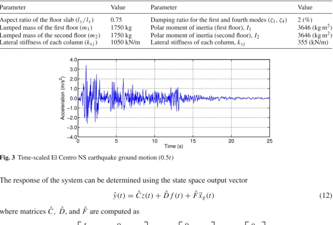
Table 1 Parameters of the two-story building structure
Parameter Value Parameter Value
Aspect ratio of the floor slab (ly/lx) 0.75 Damping ratio for the first and fourth modes (ζ1,ζ4) 2 (%) Lumped mass of the first floor (m1) 1750 kg Polar moment of inertia (first floor),I1 3646 (kg m2) Lumped mass of the second floor (m2) 1750 kg Polar moment of inertia (second floor),I2 3646 (kg m2) Lateral stiffness of each column (kx j) 1050 kN/m Lateral stiffness of each column,ky j 355 (kN/m)
Fig. 3 Time-scaled El Centro NS earthquake ground motion (0.5t)
The response of the system can be determined using the state space output vector
ˆ
y(t)= ˆC z(t)+ ˆD f(t)+ ˆFxg¨ (t) (12)
where matricesCˆ, Dˆ, andFˆ are computed as
ˆ
C = ⎡
⎣
I 0
0 I
−M−1K −M−1C
⎤
⎦, Dˆ = ⎡
⎣ 0 0 −M−1Ŵ
⎤
⎦, Fˆ = ⎡
⎣ 0 0 −λ
⎤
⎦ (13)
when displacements, velocities and accelerations of each floor/mass are being monitored. The output vector can be defined in accordance with the necessary output signals.
3 Case study
The following example presents a numerical analysis of a two-story asymmetric structure under unidirectional seismic loading to investigate the effectiveness of the semi-active control system with two MR dampers located between the base and the first floor. The properties of the lumped mass structure are given in Table1.
In this case, the asymmetric configuration of the structural system is achieved by adding an eccentric point massma=250 kg in both floors (see Fig.3). The damping matrix can be constructed in accordance with the formulation presented in Eq.9, in whichα=0.476685 andβ=0.000671.
The N-S component of theEl Centro1940 ground motion (peak acceleration of 3.42 m/s2)will be used as the unidirectional seismic excitation. The mass and stiffness properties were defined in such a way that the building structure represents a reduced scale model (1:2). Thus, the earthquake time history was scaled in time by a factor of 0.5 to characterize the magnitude of displacements that would be observed in experiments tests. In this case, the time was scaled to 20 % of the full-scale earthquake time history as displayed in Fig.3.
A numerical model of a small-size commercial MR fluid damper RD-1005-3 manufactured by LORD Corporation is used in this study. This MR damper has been widely studied to design semi-active control systems for a wide variety of engineering applications and also to investigate and derive numerical models for this type of devices. The nonlinear hysteretic behavior of MR dampers can be modeled by parametric and nonparametric models. A well-known parametric model is the modified Bouc–Wen model illustrated in Fig.4. According to the mechanical arrangement depicted in Fig.4, the predicted damper force FMR produced
by the MR damper can be computed from
Fig. 4 Modified Bouc–Wen or Spencer model [11]
in which
˙
y′= 1
c′0+c′1
ρs+c0′x˙′+k0′(x′−y′) (15)
is dependent on the evolutionary variable
˙
s=δx˙′−ζx˙′
s|s|n−1−γx˙′|s|n (16) In this formulation,k′1andc0′are the accumulator stiffness and the viscous damping observed at larger velocities, respectively. The parameterc′1is used to produce the roll-off that is observed in the experimental data at low velocities,k0′ is used to control the stiffness at large velocities andx0′ is the initial displacement associated with the nominal damper force f0due to the accumulator. Parametersζ, γ , δandnare used to control the
linearity in the unloading and the smoothness of the transition from the pre-yield to the post-yield region. Some of the modified Bouc–Wen parameters can be described by constant values, i.e., they are current-independent parameters. To take into account the influence of the magnetic field, parametersρ,c′0andc′1are usually defined as a linear function of the current, i.e., they are current-dependent parameters described by
ρ(u)=ρa+ρbu (17)
c′0(u)=c0′a+c0′bu (18)
c′1(u)= c1′a+c′1bu (19)
Besides, to accommodate the dynamics involved in the MR fluid reaching rheological equilibrium, the following first-order filter is used
˙
u= −η(u−v) (20)
in which the applied current uis described with a time delay relative to the desired currentv and ηis the time constant of the first-order filter. The model parameters of a RD-1005-03 MR damper were identified based on experimental data [12]. The current-independent parameters are:δ = 10.013, ζ = 3.044 mm−2,
γ =0.103 mm−2,k′0 =1.121 N/mm, f0 =40 N (related tox0′)andn=2 (pre-defined parameter). It was
found that the current-dependent parameters can be described by polynomial functions as follows
ρ(u)= −826.67u3+905.14u2+412.52u+38.24 [N/mm] (21)
c′0(u)= −11.73u3+10.51u2+11.02u+0.59[N s/mm] (22)
c′1(u)= −54.40u3+57.03u2+64.57u+4.73[N s/mm] (23)
and finally, the first-order filter is described byη=140 s−1.
A set of numerical simulations was carried out to determine the responses of the two-story asymmetric system. Initially, the response of the uncontrolled structure was obtained from Eq.10by setting fc =0 (i.e.,
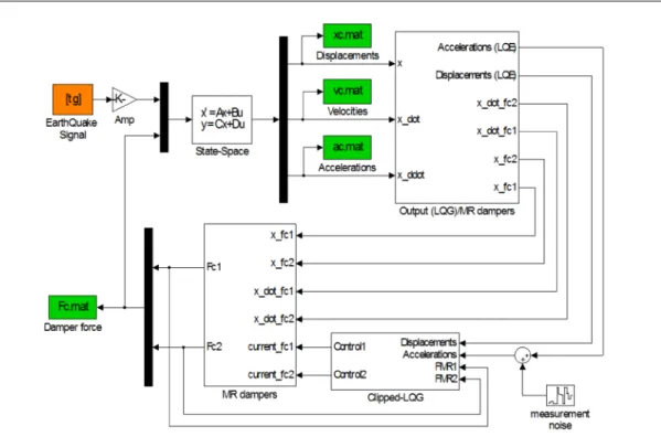
Fig. 5 Block diagram of the clipped-optimal LQG controller
in a passive control mode (i.e., as passive energy dissipation devices) producing two passive control forces fc1
and fc2along thex-direction. Finally, the MR dampers are used as semi-active actuators in combination with
a traditional optimal LQG controller. Each control mode is intended to reduce the coupled lateral–torsional response of the structural system.
All the simulations were carried out in MATLAB/Simulink. The block diagram of the semi-active LQG control system for the two-story building structure is shown in Fig.5. The controller uses floor accelerations and displacements across the dampers to compute the control signal. Indeed, a semi-active control strategy based on acceleration feedback seems to be more reliable for structural control applications instead of full-state feedback or velocity feedback controllers.
The clipped-optimal (CO) algorithm represents a traditional semi-active control strategy for MR dampers. This classical controller has proved capable of exploring in a very efficient manner the potential of these semi-active actuators, in particular the variable damping force. The main objective of the semi-semi-active controller for MR dampers is to append n force feedback loops to induce each device to produce approximately a desired control force [13–16]. In order to do this, the control strategy combines two controllers:
• A primary controller that includes an optimal control unit which is responsible for determining the optimal or desired control forces of an ideal active control system that should be applied to the structure to reduce the system response;
• A secondary controller or bistate selector (clipping system). Since only the current/voltage applied to the current driver of the MR damper can be directly controlled, this controller has the function to generate the corresponding control signal in the form of a bistate control output by clipping the optimal control forces. This accounts for the nonlinear nature of MR dampers, ensuring that they only produce dissipative forces (i.e., by adapting the ideal control action to the semi-active nature of the actuator).
In this case, the primary controller uses a linear quadratic Gaussian (LQG) regulator to compute the optimal control forces. The LQG controller combines a linear quadratic regulator (LQR) with a Kalman filter or linear quadratic estimator (LQE). The Kalman filter is used to reconstruct the state vector based on a few output measurements of a noisy system, and then, the LQR component is used to compute the optimal input signal based on the estimated state vector. The observer gainLmust be adjusted to achieve the required performance. A high gain allows the filter to follow the observations more closely, while a low gain follows the predictions more closely. This is accomplished by setting
where Ie and Im are identity matrices related to the number of excitation inputs and measurement signals,
respectively. Finally, the LQG controller is a combination of a Kalman filter (or a LQE) with a linear quadratic regulator (LQR), i.e.,
˙ˆ
x=(A−LCˆ)xˆ+Buˆ+Lyˆ ˆ
u= −Gxˆ (25)
whereGandLare the LQR and LQE gain matrices, respectively, that need to be adjusted to obtain the desired control action. The solution is based on the separation principle in which the full-state feedback controller (i.e., the LQR) and the Kalman filter are designed independently and then combined to form the LQG compensator. The selection ofQwandRvdepends on the level of accuracy attributed to the model and the measurements.
For an accurate system model measured with poor sensors, one should probably select Qwto be larger than
Rv, while for a poorly modeled system with accurate measurements, one should probably choose Rv to be
larger than Qw. A common approach is to set one of the tuning parameters and adjust the other parameter
until the result is satisfying. The key is to have a Kalman filter that removes as much noise as possible without being too slow to adapt to changes.
The secondary controller is used to convert the control forces estimated by the primary controller into a bis-tate control signal (bang–bang/on–off controller) to command the MR actuators. The damping forces generated by the MR dampers are dependent on the local responses of the structural system, and therefore, the devices cannot always produce the desired optimal control forces. Consequently, only the control voltage/current can be directly controlled to change the damper force and a force feedback loop is then incorporated in the control algorithm to make the MR damper to generate approximately the desired optimal control force. To achieve this objective, the following command signal algorithm is applied
FMR =
fc, fc· ˙x′<0
0, otherwise (26)
When the MR damper is delivering the desired optimal force, the operating voltage/current should remain the same. If the magnitude of the damper force is smaller than the magnitude of the desired optimal force and the two forces have the same sign, the voltage/current applied to the current driver is increased to the maximum level. Otherwise, the commanded voltage is set to zero. The algorithm for selecting the command signal for theith MR damper can be stated as
vi =VmaxH[(fci− fi)fi] (27)
whereVmaxis the saturation voltage/current of the MR damper, fciis the desired optimal control force, fi is
the measured damper force and His the Heaviside step function.
Hence, the clipped-optimal LQG control algorithm is a semi-active controller that combines a LQG method with a bistate selection unit. The linear optimal controller is used to compute the desired control force f based on the measured structural responses yand control force vector f applied to the structure through the semi-active device. Next, a secondary controller comprising a clipping unit generates a bistate control signal based on the optimal force calculated by the first controller so that it can be adapted to the dissipative nature of the MR damper allowing this actuator to generate approximately the desired control force [13–16]. To illustrate the application of the type of control scheme, in the present example it is assumed that acceleration measurements and displacement across the dampers are the only state variables available to design the optimal controller. A probable location of the accelerometers is depicted in Fig.6.
The translational and rotational response of the asymmetric structure is described by four accelerometers on each floor, two on thex-direction and two on the y-direction, with a total of eight accelerometers. Addi-tionally, two displacement sensors (e.g., two LVDTs) are used to measure the displacements across the two dampers, which represent the displacement of each corner of the first floor slab in thex-direction. These sensor measurements define the output response vector
ˆ
y=
x1,1,x1,2,x¨1,1,x¨1,2,y¨1,1,y¨1,2,x¨2,1,x¨2,2,y¨2,1,y¨2,2T (28)
The Kalman gain L is calculating by adjusting Qw and Rv. It is assumed that each sensor has identically
Fig. 6 Location of the measurement sensors in each floor (Eight accelerometers and two LVDTs)
Table 2 Peak responses under the time-scaled El Centro earthquake (0.5t)
Control strategy x(cm) x˙(cm/s) x¨(cm/s2) θ(rad) θ˙(rad/s) θ (¨ rad/s2) drift(cm) θ /h(rad) f(N)
Uncontrolled 1.005 28.30 813 8.6e−4 0.028 0.901 1.005 8.6e−4 –
1.652 42.76 1211 1.4e−3 0.041 1.395 0.658 5.2e−4 –
Passive 0.933 25.61 728 7.6e−4 0.024 0.805 0.933 7.6e−4 213
OFF 1.523 39.40 1100 1.2e−3 0.036 1.227 0.603 4.6e−4 183
Passive 0.540 15.03 462 3.8e−4 0.0125 0.513 0.540 3.8e−4 1546
ON 0.857 24.43 837 6.3e−4 0.0199 0.691 0.367 2.5e−4 1459
Clipped-Optimal 0.527 13.55 531 3.3e−4 0.0119 0.524 0.528 3.3e−4 1421
LQG controller 0.819 23.77 729 6.0e−4 0.0191 0.738 0.346 2.7e−4 1416
The first and second lines represent the peak responses for the first and second floors, respectively (first and second MR dampers in the case of the damper force). Passive OFF represents zero current input, and passive ON represents the maximum operating current
matricesQandrof the LQR controller must be adjusted in order to determine the state gain matrixG. In the present case, different configurations of the weighting matrix Qand the control parameterr were evaluated by measuring the effect of each combination in the system response. The following weighting parameters provided the best results in reducing the structural responses of the asymmetric system
Q=
K 0
0 0
; R=r
1 0
0 1
; r =2×10⁻⁵ (29)
It is important to note that the performance of the optimal controller is dependent on the selection of the weighting matrices. Thus, the results attained with the proposed LQG controller could be further improved by optimizing the weighting parameters with advanced search/optimization tools or soft computing techniques such as genetic algorithms or neural networks.
4 Results
A comparison of the peak responses of each control mode to those of the uncontrolled system is summarized in Table2(numbers in bold indicate reference and lower values). The results show the effectiveness of the proposed semi-active control system in reducing the coupled lateral–torsional response of the three-dimensional structure. In this case, the semi-active system outperforms the passive control modes in almost all peak responses (with exception of the angular acceleration, although with a significant reduction compared with the uncontrolled case). The results also show that using the MR dampers in a semi-active configuration results in lower peak drifts compared with the passive ON configuration. Regarding the passive control mode, it can be seen that the passive OFF configuration has almost a reduced effect in the system response (around 10 %). The passive ON mode has a major effect in the system response that results in peak responses being significantly reduced especially the torsional motions (around 55 %). As to be expected, the maximum passive control action is achieved by keeping the MR damper permanently switched on, which is clearly observable in the results of the numerical analysis.
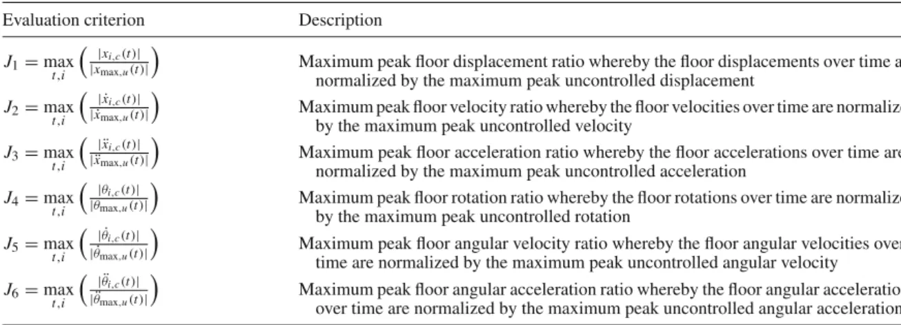
Table 3 Evaluation criteria for the structural responses (peak ratios) Evaluation criterion Description
J1=max
t,i |x
i,c(t)|
|xmax,u(t)|
Maximum peak floor displacement ratio whereby the floor displacements over time are normalized by the maximum peak uncontrolled displacement
J2=max
t,i | ˙x
i,c(t)|
| ˙xmax,u(t)|
Maximum peak floor velocity ratio whereby the floor velocities over time are normalized by the maximum peak uncontrolled velocity
J3=max
t,i | ¨x
i,c(t)|
| ¨xmax,u(t)|
Maximum peak floor acceleration ratio whereby the floor accelerations over time are normalized by the maximum peak uncontrolled acceleration
J4=max
t,i |θ
i,c(t)|
|θmax,u(t)|
Maximum peak floor rotation ratio whereby the floor rotations over time are normalized by the maximum peak uncontrolled rotation
J5=max
t,i | ˙θ
i,c(t)|
| ˙θmax,u(t)|
Maximum peak floor angular velocity ratio whereby the floor angular velocities over time are normalized by the maximum peak uncontrolled angular velocity
J6=max
t,i | ¨θ
i,c(t)|
| ¨θmax,u(t)|
Maximum peak floor angular acceleration ratio whereby the floor angular accelerations over time are normalized by the maximum peak uncontrolled angular acceleration Subscripti=1,2 denotes the story index and subscripts c and u represent controlled and uncontrolled cases
Table 4 Evaluation criteria for the structural responses (RMS ratios) Evaluation criterion Description
J7=max
t,i ||x
i,c(t)||
||xmax,u(t)||
Maximum RMS floor displacement ratio, which is given in terms of the maximum RMS absolute displacement over time with respect to the uncontrolled case
J8=max
t,i || ˙x
i,c(t)||
|| ˙xmax,u(t)||
Maximum RMS floor velocity ratio, which is given in terms of the maximum RMS absolute velocity over time with respect to the uncontrolled case
J9=max
t,i || ¨x
i,c(t)||
|| ¨xmax,u(t)||
Maximum RMS floor acceleration ratio, which is given in terms of the maximum RMS absolute acceleration over time with respect to the uncontrolled case
J10=max
t,i ||θ
i,c(t)||
||θmax,u(t)||
Maximum RMS floor rotation ratio, which is given in terms of the maximum RMS absolute rotation over time with respect to the uncontrolled case
J11=max
t,i || ˙θ
i,c(t)||
|| ˙θmax,u(t)||
Maximum RMS floor angular velocity ratio, which is given in terms of the maximum RMS absolute angular velocity over time with respect to the uncontrolled case
J12=max
t,i || ¨θ
i,c(t)||
|| ¨θmax,u(t)||
Maximum RMS floor angular acceleration ratio, which is given in terms of the maximum RMS absolute angular acceleration over time with respect to the uncontrolled case
J13=max
t,i ||d
i,c(t)||
||dmax,u(t)||
Maximum RMS inter-story drift ratio, which is given in terms of the maximum RMS absolute inter-story drift over time with respect to the uncontrolled case. Inter-story driftdi=δi/hi
Subscripti=1, 2 denotes the story index and subscripts c and u represent controlled and uncontrolled cases
overall the best performance. The proposed controller presents a performance improvement in reducing the peak responses exhibiting the best overall performance when compared with the passive configurations. The maximum ratios of the peak responses attained with this controller are generally smaller than that of passive ON configuration, with the significant exception of the angular acceleration of the second floor. Besides, the peak control force achieved by the clipped-optimal LQG algorithm has the lowest value (1416 kN).
Next, a new set of evaluation criteria including normalized and RMS responses and also control require-ments was used to complete the performance assessment of each control mode. The first six criteria (J1toJ6)
are based on the peak responses as shown in Table3.
The next six criteria (J7toJ13)are related to the RMS structural responses (see Table4). In these equations,
| · |denotes the absolute value and|| · ||is theL2norm given by
· = 1 tf tf 0
[·]2dt (30)
where tf = tmax represents the total excitation duration andtf represents a sufficient large time to allow
the response to attenuate. Finally, the last three performance indices (J14toJ16)are intended to evaluate the
Table 5 Evaluation criteria for the MR dampers (actuators)
Evaluation criterion Description
J14=max
t,j |f
j(t)|
W
Maximum control force generated during the control action normalized by the weight of the structure (whereWrepresents the total weight of the structure)
J15=max
t,j
jPj(t)
˙
xmax·W
Maximum control power normalized by (x˙max·W), i.e., the uncontrolled velocity times the weight of the structure
J16=max
t,j
jt f1
t f
0 Pj(t)
˙
xmax·W
Total power required to control the response of the structure normalized by (x˙max·W)with actuator index j= 2
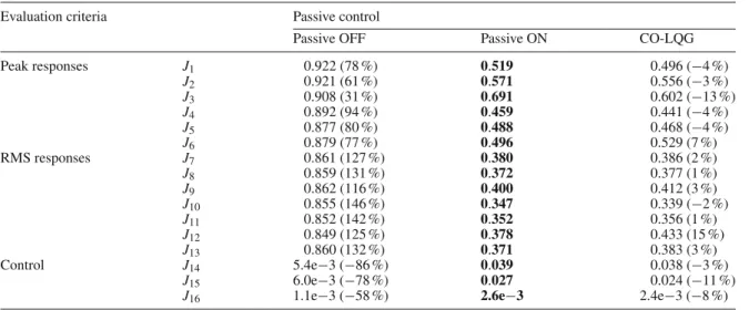
Table 6 Results of the evaluation criteria for each control strategy
Evaluation criteria Passive control
Passive OFF Passive ON CO-LQG
Peak responses J1 0.922 (78 %) 0.519 0.496 (−4 %)
J2 0.921 (61 %) 0.571 0.556 (−3 %)
J3 0.908 (31 %) 0.691 0.602 (−13 %)
J4 0.892 (94 %) 0.459 0.441 (−4 %)
J5 0.877 (80 %) 0.488 0.468 (−4 %)
J6 0.879 (77 %) 0.496 0.529 (7 %)
RMS responses J7 0.861 (127 %) 0.380 0.386 (2 %)
J8 0.859 (131 %) 0.372 0.377 (1 %)
J9 0.862 (116 %) 0.400 0.412 (3 %)
J10 0.855 (146 %) 0.347 0.339 (−2 %)
J11 0.852 (142 %) 0.352 0.356 (1 %)
J12 0.849 (125 %) 0.378 0.433 (15 %)
J13 0.860 (132 %) 0.371 0.383 (3 %)
Control J14 5.4e−3 (−86 %) 0.039 0.038 (−3 %)
J15 6.0e−3 (−78 %) 0.027 0.024 (−11 %)
J16 1.1e−3 (−58 %) 2.6e−3 2.4e−3 (−8 %)
Values under parenthesis are the percentage of reduction with respect to the passive ON case
The results achieved for each control configuration are presented in Table6. It should be noted that small values of the evaluation criteria are generally more desirable and indicate a better performance of the control system under analysis. Thus, the results highlight the effectiveness of the semi-active systems in reducing peak responses but also reveal the low performance of the proposed controllers with respect to the RMS values of the system responses in comparison with best passive control configuration.
As can be seen, the overall performance of the clipped-optimal LQG controller outperforms the passive ON mode showing a significant peak response reduction in the translational displacement of the second floor (up to 13 % compared with the passive ON mode). On the other hand, the normalized peak inter-story rotation is higher than that achieved with the best passive configuration. Regarding the RMS responses, the performance of the semi-active controller is not as good as the passive ON configuration. However, the performance obtained with the clipped-optimal LQG has almost the same RMS values of the best passive control mode (in some cases, it is slightly better than the passive system, e.g.,J10). In addition to the peak responses reduction, what
stands out in this study is the improvement in power requirements of the control system when the semi-active controller is used to command the MR dampers. The proposed semi-active controller shows an important decrease in the total power required to control the response of the structure (in this case is around 8 %). Hence, the semi-active operation of this type of actuators offers improved power efficiency while producing a better peak response reduction than that of the passive modes.
5 Conclusions
semi-active configurations with the corresponding uncontrolled response. It was verified that the proposed semi-active optimal controller allows a more efficient management of the actuators presenting in general a better performance than the passive control modes. Hence, it can be concluded that the semi-active control system outperforms a fully passive system allowing a considerable reduction in combined lateral and torsional motion of the three-dimensional plan asymmetric structure using only two MR dampers in a non-collocated configuration. Further research must be carried out to validate the application of these MR damper-based control systems to a wide range of structural configurations and with different semi-active controllers.
References
1. Jangid, R.S., Datta, T.K.: Performance of multiple tuned mass dampers system for torsionally coupled system. Earthq. Eng. Struct. Dyn.26, 307–317 (1997)
2. Goel, R.K.: Effects of supplemental viscous damping on seismic response of asymmetric-plan systems. Earthq. Eng. Struct. Dyn.27(2), 125–141 (1998)
3. Lin, W.H., Chopra, A.K.: Understanding and predicting effects of supplemental damping on seismic response of asymmetric one-storey system. Earthq. Eng. Struct. Dyn.30, 1475–1494 (2001)
4. Garcıa, M., Llera, J.C., Almazan, J.L.: Torsional balance of plan asymmetric structures with viscoelastic dampers. Eng. Struct.29, 914–932 (2007)
5. Mevada, S.V., Jangid, R.S.: Seismic response of asymmetric systems with linear and non-linear viscous dampers. Int. J. Adv. Struct. Eng.4(5), 1–20 (2012)
6. Joshi, J.H., Mevada, S.V., Patel, S.B.: Response of two-way asymmetric system with linear and non linear viscous dampers under bi-directional earthquake. Int. J. Innov. Eng. Technol.2(2), 92–102 (2013)
7. Yoshida, O., Dyke, S.J.: Response control of full-scale irregular buildings using magnetorheological dampers. J. Struct. Eng.
131(5), 734–742 (2005)
8. Yoshida, O., Dyke, S.J., Giacosa, L.M., Truman, K.Z.: Experimental verification on torsional response control of asymmetric buildings using MR dampers. Earthq. Eng. Struct. Dyn.32, 2085–2105 (2003)
9. Bharti, S.D., Shrimali M.K.: Seismic Response Control of Asymmetric Plan Building with Semiactive MR Damper, 15 WCEE, Portugal (2012)
10. Braz-Cesar, M., Barros, R.: Vibration control of asymmetric structures using MR dampers, 13th Conference on Dynamical Systems Theory and Applications DSTA 2015, Dynamical Systems: Control and Stability, vol.3, pp. 107–118 (2015) 11. Spencer Jr., B.F., Dyke, S.J., Sain, M.K., Carlson, J.D.: Phenomenological model for magnetorheological dampers. J. Eng.
Mech.123(3), 230–238 (1997)
12. Braz-César, M.: Vibration Control of Building Structures Using MR dampers, Ph.D. thesis, Faculty of Engineering of the University of Porto (2015)
13. Dyke, S.J., Spencer, B.F., Sain, M.K., Carlson, J.D.: Seismic response reduction using magnetorheological dampers. Pro-ceedings of the IFAC World Congress, USA, pp. 145–150 (1996)
14. Dyke, S.J., Spencer, B.F., Sain, M.K., Carlson, J.D.: Modeling and control of magnetorheological dampers for seismic response reduction. Smart Mater. Struct.5, 565–575 (1996)
15. Dyke, S.J., Spencer, B.F.: A comparison of semi-active control strategies for the MR damper. IASTED International Con-ference on Intelligent Information Systems. IEEE Computer Society, pp. 580–584 (1997)

![Fig. 4 Modified Bouc–Wen or Spencer model [11] in which y˙ ′ = 1 c ′ 0 + c ′ 1 ρs + c 0′ x˙ ′ + k 0′ (x ′ − y ′ ) (15) is dependent on the evolutionary variable](https://thumb-eu.123doks.com/thumbv2/123dok_br/16985058.763218/6.892.116.776.120.505/fig-modified-bouc-spencer-model-dependent-evolutionary-variable.webp)