Full Terms & Conditions of access and use can be found at
http://www.tandfonline.com/action/journalInformation?journalCode=uarc20
International Journal of Architectural Heritage
Conservation, Analysis, and Restoration
ISSN: 1558-3058 (Print) 1558-3066 (Online) Journal homepage: http://www.tandfonline.com/loi/uarc20
Earth-based Render of Tabique Walls – An
Experimental Work Contribution
Jorge Pinto, Sandra Cunha, Nuno Soares, Edgar Soares, Vítor M. C. F. Cunha,
Débora Ferreira & Ana Briga Sá
To cite this article: Jorge Pinto, Sandra Cunha, Nuno Soares, Edgar Soares, Vítor M. C. F. Cunha, Débora Ferreira & Ana Briga Sá (2017) Earth-based Render of Tabique Walls – An
Experimental Work Contribution, International Journal of Architectural Heritage, 11:2, 185-197, DOI: 10.1080/15583058.2015.1020459
To link to this article: https://doi.org/10.1080/15583058.2015.1020459
Published online: 27 Oct 2016.
Submit your article to this journal
Article views: 114
View related articles
View Crossmark data
Earth-based Render of Tabique Walls
–
An Experimental Work Contribution
Jorge Pintoa,b, Sandra Cunha a,b, Nuno Soaresa, Edgar Soaresa,b, Vítor M. C. F. Cunha c, Débora Ferreirab,d, and Ana Briga Sá a,b
aUniversity of Trás-os-Montes e Alto Douro, School of Science and Technology, Engineering Department, Vila Real, Portugal;bC-MADE, University of Beira Interior, Covilhã, Portugal;cISISE, Civil Engineering Department, University of Minho, Guimarães, Portugal;dPolytechnic Institute of Bragança, High School of Technology and Management, Bragança, Portugal
ABSTRACT
A research work focused on studying earth render for tabique application purposes is presented. Initially, a brief description of the tabique building technique is provided. The relevance of the applica-tion of this tradiapplica-tional building technique is also highlighted. Different composiapplica-tions of earth render are experimentally analyzed and the respective performance is evaluated. Flexural and compressive strengths, workability, drying shrinkage cracking, and water resistance are the material properties assessed. A simple earth render is selected as being adequate for tabique building applications and it is applied on the manufacturing of a tabique wall sample. This wall sample is monitored in terms of thermal insulation ability and its thermal transmission coefficient is estimated. Taking into account that there is still a lack of published technical information related to this topic, this article may contribute to solve this limitation and to give some guidance in future repairing processes of tabique construction. The technological benefit of adding lime or cement with earth is researched. Real tabique timber structure samples are applied in order to validate the obtained experimental results.
ARTICLE HISTORY Received 31 October 2014 Accepted 14 February 2015 KEYWORDS
earth; material properties; raw material; render;
sustainability;Tabique;
traditional building techniques; wall
1. Introduction
In the building industry there is an increasing trend of choosing raw and organic building materials as an alternative to the application of industrialized materials. Sustainability and affordability are two attributes that justify this building option. For example, stone, timber, earth, sand, clay, cork, and bamboo (Bui et al., 2009; Brás, Gonçalves, and Faustino2014; Cherki et al.2014; Ciancio, Jaquin, and Walker 2013; Escamilla and Habert 2014; Feio et al. 2013; Hendry 2001; Silva et al. 2013) are some traditional building materials that match these requirements. Taking into account that traditional building techniques apply these types of materials, focusing on their study may result in improving the knowledge related to the application of these building materials (Coroado et al. 2010; Veiga et al.2010).
Adobe, rammed earth and tabique are traditional building techniques applied worldwide, which use earth as a building material (Guffroy 2008; Jaquin, Augarde, and Gerrard2008; Robben1989). Earth plays an impor-tant structural role in the adobe and the rammed earth contexts. On the other hand, it is extremely relevant as a finishing building element in the tabique building
technique. In fact, it is applied as the major constituent of earth renders to cover the timber structural frames that characterize atabiquebuilding element. An earth render protects the timber structure and gives technological attri-butes to the element. For instance, some of these techno-logical attributes are water and fire resistance, as well as thermal and acoustic insulation. Thus, an earth render plays a key role in the behavior and in the durability of a tabiquebuilding element such as a wall.
Usually,tabiquewalls present a certain vulnerability to water. The impact of the rain on externaltabiquewall may generate a mechanical, physical, and chemical deteriorat-ing process of the earth render enddeteriorat-ing up causdeteriorat-ing damage. The degradation of the earth render may also affect the conservation of the timber structure, and consequently, the durability of the building may be put in risk. The penetration of rainwater and the humidity in the element will also influence its thermal conductivity. The latter scenario justifies the fact that it is common to coat exter-nallytabiquewalls with water resistant solutions, such as metal corrugated sheets or schist tiles.
In the earth render context a hydraulic binder (e.g., lime or cement) is not considered necessarily as a con-stituent. Meanwhile, a soil with a certain plasticity is
CONTACTSandra Cunha [email protected] University of Trás-os-Montes e Alto Douro, School of Science and Technologie, Engineering Department, Vila Real, Portugal and C-MADE, University of Beira Interior, Covilhã, Portugal.
Color versions of one or more of the figures in the article can be found online atwww.tandfonline.com/uarc.
2017, VOL. 11, NO. 2, 185–197
http://dx.doi.org/10.1080/15583058.2015.1020459
used instead of sand exclusively. Probably, these are the major technical aspects that differentiate an earth ren-der from a cement-based renren-der.
According to research work performed in the tabique construction context (Pinto et al. 2014) it has been con-cluded that this type of traditional construction is very likely to require measures of repairing, due to its age and also due to the lack of a proper maintenance policy. At the same time, there is still a lack of international design codes concerning earth construction and also of published tech-nical information related to tabique construction. Thus, there are some technical constraints when actions of con-servation or repairing of tabique construction are necessary.
Therefore, the main goal of this research work is to provide guidance in terms of earth renders for tabique building application purposes. In addition, a contribu-tion to the knowledge of the thermal insulacontribu-tion proper-ties of tabiquewalls is also given.
Although tabique is a Portuguese terminology, this traditional building technology has similarities with other techniques, with different designations, and which are from other parts of the world. For instance, in Brazil,pau a pique, taipa de mão, andtaipa de sebe, are three common designations of this building techni-que (or similar). On the other hand, in other South American countries such as Chile or Peru, quincha, is the terminology adopted. Meanwhile, the Anglo-Saxon terminology used is wattle and daub. Therefore,tabique construction may have a worldwide incidence. This fact may also justify the relevance of this research work.
This article is structured as follows. First, a summary of the existing tabique construction in the north-east region of Portugal is provided. Second, a summarized reviewing of traditional earth renders oftabiquewalls is also introduced. Third, some material properties of different earth renders are experimentally evaluated. Flexural and compressive strengths, workability, drying
shrinkage cracking, and water resistance are analyzed for different six earth renders. At the same time, one of these earth render samples was selected for tabique building applications purposes and the thermal insula-tion behavior of a tabique wall sample built with that selected render is also assessed in this section. Finally, the main conclusions are drawn.
2. Brief description of tabique construction
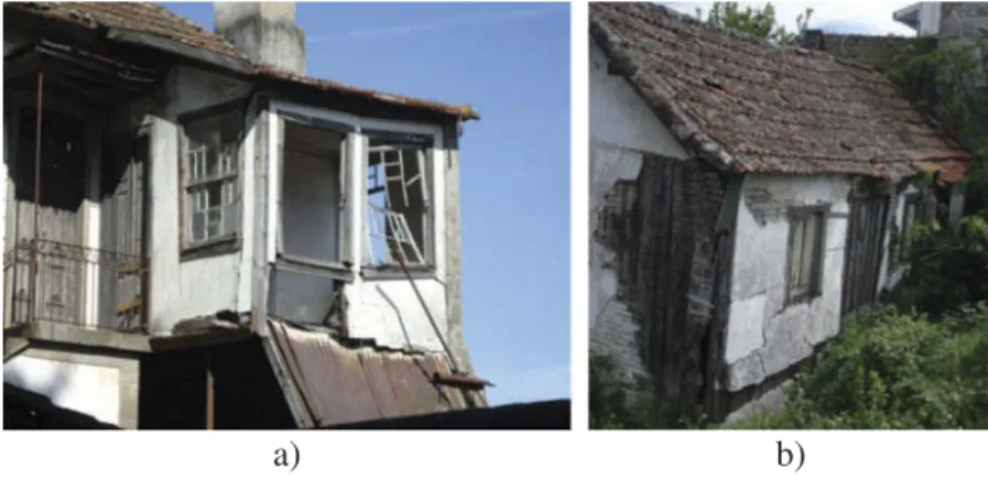
Tabique construction corresponds to a relevant Portuguese heritage. The tabique building technique was currently applied until the introduction and dis-semination of the reinforced concrete construction technique. Therefore, the Portuguese urban city centers are very likely built according to tabique technique. Urban and rural tabique construction characteristics are differentiated in (Cardoso 2013). In general, a tabi-que construction corresponds to a dwelling. It tends to have several floors (Cardoso2013; Pinto et al.2014). A tabique bungalow is an uncommon typology solution. For instance, a two-floor dwelling and a tabique bun-galow are presented in Figures 1a and1b, respectively. Walls and chimneys are the main tabique building components. The walls may be exterior or partition. In the case of exterior tabique walls, these correspond to the main vertical structural elements of a building and they tend to be stiffer by presenting a more robust timber frame solution (Cardoso 2013). It has been reported (Pinto et al. 2014) that the partition tabique walls are also relevant in terms of structural behavior because they may work as a bracing solution of the main structural elements. Although, the timber frame of a partition wall tends to be lighter than the respective frame of exterior walls, they may have the same type of timber frame solution such as a set of vertical and horizontal timber boards connected to each other. Traditionally, a tabique dwelling presents stone (e.g.,
b) a)
granite or schist) masonry walls at the cellar and ground floor, and tabique walls (e.g., exterior and/or interior) in the upper floors. In this type of building typology, the main horizontal structural elements are timber floors. Briefly, a tabiquebuilding component is formed by a timber structural frame system covered with an earth render. There are different alternative solutions for the timber structural frame. Vertical tim-ber boards linked to each other by a set of horizontal timber boards is a commonly applied timber structural frame solution. The horizontal timber boards are applied on both sides of the vertical timber boards. These horizontal elements also have an important func-tion of improving the adhesion of the earth render to the timber structure. The timber elements are nailed to each other.
At the present time, the Portuguese tabique con-struction tends to present signs of deterioration. The tabique buildings shown in Figure 1 are examples of this situation. A lack of a proper regular maintenance has been pointed out as being the main cause of this fact. Therefore, repairing actions are required. In order to carry out a proper repairing process it is required to know the specific technological aspects concerning this type of traditional building technique. This paper intends to give a contribution to this issue by studying earth renders. Earth render plays a key building func-tionality in the tabique context because it protects the timber structure by increasing its durability (Cardoso
2013; Pinto et al.2014). In fact, earth render increases the fire resistance of the wall and protects the timber structure from the biological attack of insects and fungus.
3. Traditional earth render of tabiquewalls
More than 300tabiquebuildings existing in the north-east part of Portugal have already been studied (Cardoso
2013; Pinto et al. 2014) in order to contribute to the characterization of this valuable Portuguese heritage. The building typologies, the building materials (e.g., the filling of thetabiquecomponents, the species of the wood of the frame, the type of nails), the constructive solutions and the building details, the structural and non-structural defects and their causes and the possible rehabilitation solutions (structural and non-structural) are some of the technical aspects that have been under research concerning the tabique building technique (Pinto et al.2014). In relation to the characterization of the commonly applied filling more than 60 filling sam-ples oftabiquewalls were collected and experimentally studied in terms of granulometry, elementary mineral composition, and elementary chemical composition.
Granulometric analysis, X-ray diffractometry test, and scanning electron microscopy/energy dispersive spec-troscopy analysis (SEM/EDS) were the experimental techniques performed in this study.
The granulometry results indicated that a ratio of 20% of thin particles (size smaller than 0.5 mm) and 80% of medium sized particles (in between 0.5 mm and 2 mm) may be considered as being a traditional soil mixture for the filling material oftabiquecomponents. The earth has been characterized as being granite related. Additionally, a lime earth-based render (inci-dence of 70%) and simple earthy render (inci(inci-dence of 30%) were the identified render solutions currently applied as filling of tabique components. It was not possible to identify the amount of water and lime incorporated in the present research work. Therefore, this article intends to give a contribution to this matter by studying six different mixes of earth render.
4. Material properties of different earth renders
In order to prepare a tabiquewall sample for thermal insulation behavior analysis, an earth render had to be prepared. Therefore, it was necessary to collect a soil and a mix composition had to be chosen. Being local and having a similar granulometry to the earth render of the region’s referencetabiquewall were two of the main key conditions to select the soil. Considering that earth and a mixture of earth and lime are the main compositions of the traditional earth render applied in tabique building components (Cardoso 2013; Pinto et al. 2014), different mixes were studied. In this case, the flexural and the com-pressive strengths, the workability, the drying shrink-age cracking, and the water resistance were the material properties experimentally assessed to charac-terize the performance of each earth render. A description of the experimental work done, the pre-sentation of the main results and the respective dis-cussions are detailed in the following sections.
4.1. Granulometry
solution is currently applied in both exterior and parti-tion walls (Pinto et al.2014).
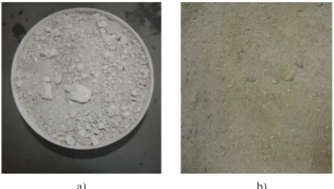
The remains of the earth render of the tabique wall were collected (Figure 3a) and ground. The granulometry of this material was assessed,Figure 4. In terms of particle size, this material seems to be formed by 10% of silt, 65%
of sand, and 25% of gravel. In terms of amount of thin particles (particle size smaller than 0.5 mm), it corre-sponds to 20%, approximately. These percentages are typical in the tabique context (Pinto et al. 2014). It is worth mentioning that the color of the material (greyish color,Figures 2band3a), its high consistency and appar-ent strength are indicators that lime was applied in this earth render. This fact may have affected the results of the granulometric analysis. The amount of thin particles may have increased because of the existence of the lime parti-cles. Moreover, the amount of thick particles (particle sized bigger than 2 mm) may have also increased because the agglutination of the soil particles which resulted from the addition of lime may have made the disintegration process difficult. Meanwhile, a sample of local soil was picked up and its granulometry was also assessed,Figures 3band4. Comparing the obtained granulometric curves,
Figure 4, it is concluded that the earth render of the referencetabiquewall and the picked soil have a similar granulometry. Therefore, the respective soil was assumed
I
II
III
II
I
IV
Key: I – vertical board; II – horizontal board; III – earthy render; IV – nail b)
a)
Figure 2.Usedtabiquewall: a) wall and b) detail.
b) a)
Figure 3.Studied materials in terms of granulometry: a) earth render of the referencetabiquewall sample and b) collected soil.
Clay Silt Sand Gravel
0.01 0.1 1 10 100
Particle size (mm)
Earthy render Collected soil
0 10 20 30 40 50 60 70 80 90 100
Cumula
ti
ve
we
ight
pa
ssi
ng
(%)
to be adequate for filling purposes of tabique building components.
4.2. Earth render mixes
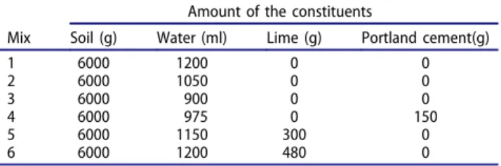
As it was previously stated, different mixes of earth render were studied in this research work. In fact, six mixes were considered. Three renders did not comprise any hydraulic binder, corresponding to having exclu-sively soil and different amount of water. These renders are designated as Mix 1, Mix 2, and Mix 3. Table 1
includes the mix composition for these renders. The respective soil:water ratio (in terms of weight) was 5:1, 5.7:1, and 6.7:1. On the other hand, two earth renders considered the addition of lime. These renders were Mix 5 and Mix 6, and the respective constituent soil: water:lime ratio was 20:3.8:1 and 12.5:2.5:1, Table 1. Finally, an earth render considering Portland cement as binder was also prepared according to the 40:6.5:1 ratio (soil:water:cement), designated as Mix 4 in
Table 1. Among these renders, only Mix 4 is not tradi-tional in the tabique context. However, its study seemed to be pertinent in order to assess its attributes.
4.3. Flexural and compressive strengths
Ten samples of each earth render mix were prepared in order to be tested in terms of bending and com-pression at the age of 30 days and according to (NP EN 196-1—Methods of testing cement 1996). The
curing process occurred under the controlled thermo-hygrometric conditions of a climate chamber (temperature of 20ºC and a relative humidity of 40%). A Seydner Mega 10/250/15D testing rig was used to assess the mechanical properties, namely, its ultimate loading capacities, under bending (Figure 5a) and compression (Figure 5b). The tests were carried out in force control with a load rate of 5 and 24 N/s, respectively, for the bending and com-pressive tests. The flexural and comcom-pressive bearing capacity was 15 and 250 kN, respectively. The com-pression samples were obtained from the two halves of the prismatic samples tested in bending. Therefore, 60 samples were tested in bending (i.e., 10 per each earth render mix) and 120 samples were tested in compression (i.e., 20 per each earth render mix).
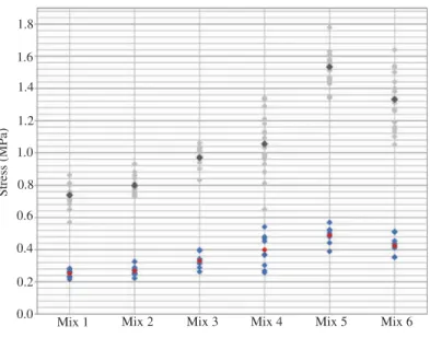
The obtained flexural (F) and compressive (C) strengths are plotted in Figure 6. The average flexural and compressive strength values are also featured in
Figure 6. According to the data of Figure 6some con-clusions are ascertained in terms of the mechanical behavior of the earth render of tabique building com-ponents. The inclusion of a hydraulic binder tends to increase the mechanical behavior of the earth render, as also evidenced in other studies, e.g., Livesey (2002) and Veiga et al. (2010). In fact, Mixes 4, 5, and 6 have higher compressive and flexural strengths than Mixes 1, 2, and 3. Adding lime instead of cement seems to have a meaningful benefit in terms of the mechanical behavior. At the same time, an increase in the amount of water also improves the strength of the material. Mixes 1, 2, and 3 are a clear example of this fact. Generally, an increase in the amount of a binder tends to be associated with an increase in the amount of water. Consequently, the respective expected strength improvement may not occur. This situation occurred between Mixes 5 and 6, in which an increas-ing of lime (from 300–480 g, Table 1) resulted in a degradation of the mechanical behavior of the render
Table 1.Analyzed earthy render mixes.
Mix
Amount of the constituents
Soil (g) Water (ml) Lime (g) Portland cement(g)
1 6000 1200 0 0
2 6000 1050 0 0
3 6000 900 0 0
4 6000 975 0 150
5 6000 1150 300 0
6 6000 1200 480 0
b) a)
(average compressive strength varying from 1.53 MPa to 1.33 MPa and average bending strength varying from 0.49 MPa to 0.42 MPa; Figure 6). In addition, these results also corroborate the fact that earth-based build-ing materials have a better behavior in compression than in tension. In terms of failure modes, Figure 5a
indicates that a very well defined crack was formed approximately in the middle span of the earth render sample tested in bending. This type of failure mode occurred similarly in all the tested samples. Meanwhile,Figure 5bfeatures the typical failure mode observed in the uniaxial compressive test (i.e., under-lined in red, Figure 6b). It is worth referring that the occurring failure modes are similar to the ones occurred in currently applied building material (e.g., cement-based render, concrete, or stone) when they are tested in the same context.
4.4. Workability
An adequate workability is an important expected attri-bute in an earth render of a tabique building compo-nent. Technical aspects such as mixing, adhesion, handling, and finishing may influence this material property of an earth render. In order to evaluate the workability of the earth render of tabique building components a scale was defined as follows: very diffi-cult (1 point); diffidiffi-cult (2 points); moderate (3 points); good (4 points); very good (5 points). On the other hand, a simple experimental set-up was adopted con-sisting of rendering a portion of a timber structure of a realtabiquewall,Figure 7. The different mixes of earth
render were applied on this structural element.Figure 7
gives some highlights of this experimental procedure in which a mix of an earth render is already applied (Mix 1) on the timber structure and another one (Mix 2) is in progress in terms of application. Through the latter figure it is also noticeable that the timber structure is rough or even furrowed, in order to facilitate the adhe-sion of the earth render on the timber structure. This is a traditional practice in the tabiquecontext. Each earth render mix, Table 1, was applied in order to fill the existing gap between the timber elements and also to form a layer of 1.5 cm of thickness. During the applica-tion process of each render, the above-menapplica-tioned tech-nological aspects were evaluated, and their classification is summarized in Table 2. Considering the specific
Compression (C) Average in C Flexural (F) Average in F
Mix 1 Mix 2 Mix 3 Mix 4 Mix 5 Mix 6
0.0 0.2 0.4 0.6 0.8 1.0 1.2 1.4 1.6 1.8
Stress (MPa)
Figure 6.Flexural (F) and compressive (C) strengths.
0.25 0.25
Mix 1
II
Mix 2
I
Key: I – portion of a timber structure of a tabique wall; II – auxiliary timber board
Figure 7.Workability assessment (units in meters).
Table 2.Qualitative assessment of the technological para-meters (scale 0–5 being 0 worst and 5 the best).
Technical characteristic Mix 1 Mix 2 Mix 3 Mix 4 Mix 5 Mix 6
Mixing 5 3 2 2 3 3
Adhesion 3 3 1 3 4 4
Handling 4 4 2 3 3 3
Finishing 4 3 2 4 4 4
technical particularities under research (earth-based render and timber-based wall), this expedite experi-mental set up was adopted instead of the slump flow test.
According to the proposed evaluation procedure, Mix 1 was the studied earth render that presented better workability because it obtained the higher rate (a rate of 16 points,Table 2). In fact, in the case of Mix 1, it was easy to mix the constituents, the render showed an adequate adhesion to the timber structure, it also was handled and it allowed a good finishing,Figure 7. Based on the data of Table 2, the adhesion seems to be the vulnerable technical aspect of Mix 1. At the same time, Mix 1 is followed by Mixes 5 and 6 in terms of work-ability. Mixes 5 and 6 obtained a rate of 14 points which represents a good workability. These mixes include lime as a constituent. The increase in the amount of lime was also followed by an increase in the amount of water and it may explain the fact that the workability was not affected. The addition of cement does not seem to ben-efit the workability of an earth render. In fact, it is necessary to increase the amount of water. The amount of water is a key factor for the workability performance of an earth render. This technical aspect is emphasized when Mixes 1, 2, and 3 are compared in terms of work-ability, Table 2. A reduction of the amount of water tends to reduce disproportionally the workability of the material. For instance, in Mixes 1 and 3 there was a
300 mL reduction (Table 1) of the water content and the respective workability performances dropped 9 points (from 16 to 7,Table 2).
4.5. Drying shrinkage cracking
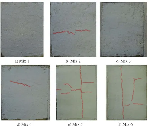
Another important material property of an earth render of atabiquebuilding component is the drying shrinkage cracking tendency. Taking into account that it is expected to apply earth render on exteriortabiquewalls and that it is likely that this building component will not have any additional coating element, this material property is rele-vant in terms of durability. Apart from the quality of the render, the conditions of its application may also affect this cracking phenomenon. For instance, high tempera-ture and dry timber support are some undesirable condi-tions. In order to analyze the susceptibility of each of the six earth renders under research in terms of this phenom-enon, the samples processed for the workability assess-ment (previous section) were then dried naturally during 30 consecutive days and under the controlled thermo-hygrometric conditions of the laboratory. During this period of time the samples were visually monitored in order to check the drying shrinkage cracking appearance. The obtained experimental results are presented in
Figure 8in which the cracks due to drying shrinkage are identified in red for each earth render.
a) Mix 1 b) Mix 2 c) Mix 3
d) Mix 4 e) Mix 5 f) Mix 6
In general, the six different earth renders behaved adequately in terms of drying shrinkage because an impressive cracking pathology scenario did not occur in any case. Mixes 1 and 3 did not present any visible cracking,Figures 8aand8c. It is worth underlining that these renders are processed exclusively with soil and water,Table 1. This building scenario corresponds to a traditional practise in thetabiqueconstruction. On the other hand, few cracks resulted from the natural drying of Mixes 2 and 4,Figure 8band8d, respectively. Mix 2 also corresponds to a render processed with soil and water and Mix 4 includes cement as a constituent,
Table 1. However, these cracks are not expressive in terms of size. Meanwhile, Mixes 5 and 6 were more affected in terms of cracking appearance by the drying process, Figures 8e and 8f, respectively. In these last two cases, the amount of cracks and their expressive-ness were higher. In fact, in both cases, Figures 8eand
8f, there is a longitudinal crack. Mixes 5 and 6 include lime as a binder which is a traditional technique in this context. Probably, in these two cases, the amount of water added in the mixtures was excessive or indeed not adequate for cracking to appear. Generally, the cracks tend to be formed from the centre to the edge of the sample. Based on this information, it is possible to conclude that the inclusion of a hydraulic binder such as lime or cement does not seem to improve the quality of an earth render in terms of drying shrinkage cracking phenomenon. In fact, it tends to increase the susceptibility of the appearance of cracks due to the drying shrinkage, in particular, when lime is added. Aspects such as the number of the samples and the size of the adopted samples may limit the representa-tiveness of these conclusions and it may justify further research in this matter.
4.6. Water resistance
Another relevant material property that has to be con-sidered in earth renders of tabique construction is the water resistance. Similarly to the other traditional earth building techniques such as adobe or rammed earth, a tabiquebuilding component is also vulnerable to water. This susceptibility is even higher if the component is placed in the exterior (e.g., an exteriortabiquewall) and exposed to the rain. This fact justifies that these walls are currently coated with an additional element such as metal corrugated plates or schist tiles, among other possibilities. Therefore, the earth renders subjected to this research work were also tested in terms of water resistance. For this purpose, the samples used in the workability and in the drying shrinkage cracking studies were also applied in this context. In order to simulate in
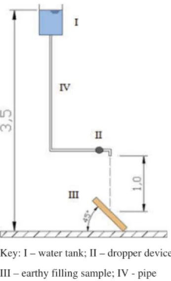
laboratory the mechanical impact of the rain on an exteriortabiquewall an expedite set up was also specifi-cally prepared to perform the water resistance test. The adopted set up is schematically presented inFigure 9and it consists of a device formed by a water tank, a pipe and a dropper. The water tank is placed at a height of 3.5 m in order to allow the water dropping by gravity. On the other hand, the drops fall at a distance of 1.0 m until reaching the earth render sample, which is positioned obliquely and forming an angle of 45º with the horizon-tal direction, Figure 9. The dropper allows controlling the intensity of drops falling on the sample.
Each earth render mix was tested in terms of water resistance. The duration of each water resistance test and the respective number of drops are shown in
Table 3, and the respective damage due to the succes-sive impact of the drops is presented in Figure 10. In this context, total damage of the sample corresponds to the complete loss of the material in the location where the drops fell. Therefore, it is a local total damage. When the duration of a test was 24:00:00 (hours:min-utes:seconds) there was no total damage.
Thus, Mixes 5 and 6 had shown adequate water resistance ability because they did not face any damage for 1 day under the continuous mechanical effect of the impact of 172,800 drops falling from a 1 m distance.
Key: I – water tank; II – dropper device;
III – earthy filling sample; IV - pipe
Figure 9.Adopted water resistance testing set up (units in meters).
Table 3. Water resistance testing results (h—hours; min—
min-utes; s—seconds).
Duration (h:min:s) Number of drops
Mix 1 0:38:15 4590
Mix 2 0:44:32 5344
Mix 3 0:51:47 6214
Mix 4 4:27:17 32074
Mix 5 24:00:00 172800
These earth samples kept their integrity, Figures 10e
and 10f. In contrast, Mixes 1, 2, and 3 showed a very vulnerable behavior in terms of water resistance. In fact, they faced total damage in less than 01:00:00 h: m:s after being exposed to the impact of the falling of drops, Table 3. Figures 10a, 10b and 10c show the extent of the occurred damage in these earth render mixes. Finally, Mix 4 also showed vulnerability in terms of water resistance because it reached total damage in less than 05:00:00 h:m:s,Figure 10dandTable 3. Based on these results, we may conclude that the inclusion of a hydraulic binder tends to improve the water resis-tance behavior of an earth render of tabique construc-tion, in particular, if that binder is lime. The fact that this improvement is not significant by adding cement as a binder may be related with material compatibility concerning the used soil and cement. Further research regarding this topic should be carried out.
4.7. Thermal insulation behavior
In order to estimate the thermal insulation ability of a tabiquewall it was necessary to select a mix among the six mixes of earth renders studied. According to the results presented in the previous section, we may con-sider that Mix 5 obtained adequate quality in terms of
earthy render showing, simultaneously, the best mechanical performance, a very good workability and proper water resistance. It only showed certain vulner-ability in terms of the drying shrinkage cracking phe-nomenon. Meanwhile, Mix 1 also had shown acceptable achievement as an earth render oftabiqueconstruction. In spite of being extremely susceptible to water Mix 1 did not present any visible cracking due to drying shrinkage. This technical aspect may be relevant in terms of durability of the element and, in particular, in terms of thermal insulation performance. As it was stated earlier, coating this type of wall with a water-proof system is a traditional applied building solution thus, the water vulnerability of Mix 1 may be mini-mized. Therefore, at this stage, Mix 1 was the selected earth render to conduct the thermal insulation analysis. Being traditional and being simple (i.e., without the inclusion of a binder) were two additional attributes of Mix 1 that helped this decision.
4.7.1. Sample preparation
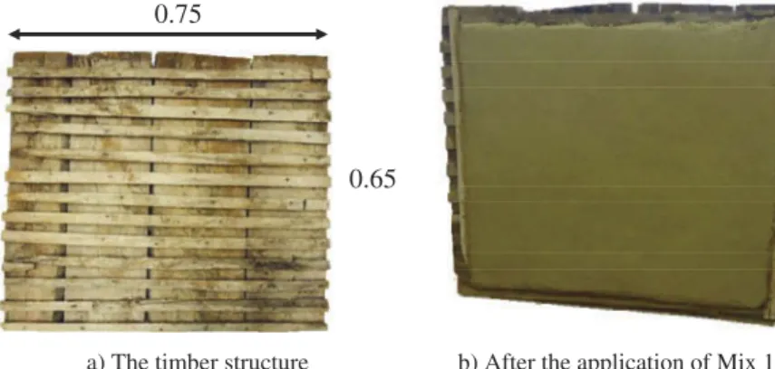
In this research work, it was necessary to build a 0.75 m × 0.65 m (width × height) sample of a tabique wall,Figure 11. In this part, the used timber structure is also a portion of the timber structure of the realtabique wall depicted in Figure 2a. Pinus pinaster was the
a) Mix 1 b) Mix 2 c) Mix 3
d) Mix 4 e) Mix 5 f) Mix 6
identified species of the timber elements of the wall. The timber structural system of the wall is composed of vertical timber boards connected to each other by tim-ber horizontal boards, which are nailed on the vertical boards on both sides. In terms of medium values, the vertical boards presented a width of 0.164 m, a thick-ness of 0.025 m, and a gap between them of 0.003 m. Meanwhile, the horizontal boards had the following average dimensions, width of 0.026 m and thickness of 0.018 m, and they were separated from each other by 0.021 m. Mix 1 was the earth render applied on the timber structure, on both sides, in order to wrap com-pletely the timber elements and to assure a 0.015 m thickness layer of covering. Thus, this wall system has a thickness of 0.091 m. After the application of this earth render on the timber structure, the drying process occurred during 30 consecutive days under the con-trolled thermal-hygrometric conditions of the labora-tory. After this period of time, thetabiquewall sample was ready to be thermally tested.
4.7.2. Experimental set up
The experimental work was performed in a laboratory, where a thermal test room was used as an alternative
solution of a thermal test cell. The thermal test room measures are 4.00 m × 3.00 m × 2.54 m (length × width × height) and it is thermally controlled. This experimental procedure has been successfully applied in previous research works such as (Paiva et al. 2012). To guarantee the validity of the experimental work it was necessary to ensure that the temperature of the internal environment remained stable and always higher than the temperature of the external environment. An approximately constant interior temperature of the thermal test room was guaran-teed by using a domestic heater in the room which was continuously switched on during the test performance. This control of the temperature allows the heat flux to occur always from inside to outside.
The sample of the tabique wall replaced an existing window in the northeast façade of the test room,
Figure 12. The sample was carefully fixed to the wall of the test room by polyurethane foam (II,Figure 12). This fixation solution also avoided undesirable insulation voids, thermal bridges, non-insulated headers, and other faults which may compromise the feasibility of the final thermal results.
According to ISO 9869 (ISO 98691994), the recom-mended equipment apparatus is composed by two heat 0.75
0.65
a) The timber structure b) After the application of Mix 1
Figure 11.Building systems of the tabique wall sample for thermal insulation testing.
I
II
1
III
2
II
IV
b) Outer face a) Inner face
Key: I – Inner face of the wall sample, earthy render finishing; II - Polyurethane foam;
III – Temperature sensors; IV – Outer face of the wall sample; 1 and 2 – Heat flowmeters.
flowmeters (1 and 2,Figure 12a), four surface tempera-ture sensors (III,Figure 12a), two ambient temperature sensors, a data logger and a computer. Both heat flow-meters and surface temperature sensors were fixed in the middle of the inner face of the wall,Figure 12a. The interior and the exterior temperatures (Ti(n)andTe(n)) were measured using thermo hygrometric equipment kept indoors and outdoors, respectively.
In this research work, the temperatures (Ti(n) and Te(n)) and the heat flow across the wall model (q1(n) and q2(n)) were measured continuously (in-between 10-min intervals (n)). The heat flowmeters 1 and 2 (Figure 12a) measured the heat flow occurring across the wall sampleq1(n)andq2(n), respectively.
Although the values obtained from the four tem-perature sensors are not directly used for calculating the thermal transmission coefficient of the analyzed sample, they allow verifying if the values obtained dur-ing the measurement period are reliable. If any of the acquired values fall outside the magnitude of the remaining values, it is necessary to identify the cause and remove those values from the measurement period. Similar analysis is performed for the relative humidity values obtained using the thermo hygrometric equip-ment. The values of these parameters are therefore used to identify influencing variables of the experimental test, contributing to its validation.
There was no drying shrinkage cracking appearance due to drying of the tabique wall sample as Figure 12
shows.
4.7.3. Methodology
The methodology used to analyze the thermal insula-tion performance of thetabiquewall sample was based on an experimental work done according to ISO 9869 entitled Thermal Insulation: Building Elements—In Situ Measurement of Thermal Resistance and Thermal Transmittance (ISO 98691994). According to the inter-national standard (ISO 98691994), the thermal trans-mission coefficient (U) of a material or a building system can be quantified applying Equation (1):
U‘ðntotalÞ ¼U1ðntotalÞ þU2ðntotalÞ
2 : (1)
In which,q(n)is the heat flow across the wall sample in the moment n;Ti(n) andTe(n)are the interior and the exterior temperatures in the moment n, respec-tively;ntotal is the total number of moments in which the data was collected.
Taking into account that two heat flowmeters were used corresponding toq1(n)andq2(n), it is possible to estimate two thermal transmission coefficients, U1(nto-tal)andU2(ntotal), which are the thermal transmission
coefficients related to the data registered by the heat flowmeters 1 and 2, respectively, by applying Equation (1). Thus, the thermal transmission coefficient of the wall model (U`(ntotal)) is the average value of U1(nto-tal)andU2(ntotal) and according to Equation (2):
U‘ðntotalÞ ¼U1ðntotalÞ þU2ðntotalÞ
2 : (2)
According to the standard (ISO 98691994), a mini-mum of 3 days test duration is required if the tempera-ture is stable around the heat flowmeters. Otherwise, this duration may be more than 7 days for precaution depending on the thermal inertia of the building com-ponent. Based on the above-described constitution of the tabique wall sample, the respective thermal inertia of this type of traditional building element may be considered low and, consequently, a minimum of 3 days test duration is acceptable according to (ISO 9869 1994).
4.7.4. Experimental results and discussion
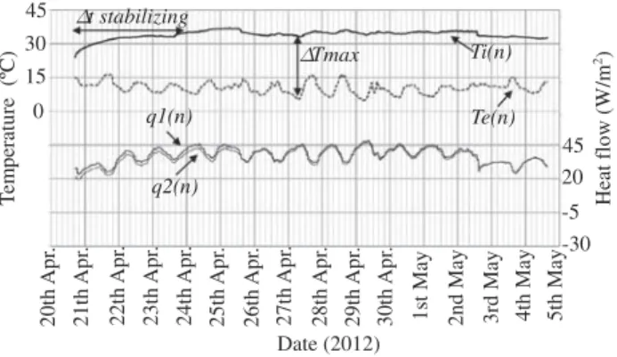
The thermal insulation test was performed during April and May of 2012, having duration of 14 days,Figure 13. Therefore, the 3 days recommended minimum test duration was guaranteed. In fact, 3 days was approxi-mately the required time to stabilize the interior tem-perature (Δt stabilizing) of the room. As it was stated earlier, this interior thermal condition was achieved by using a domestic heater in the test room which was constantly switched on during the test. It was possible to stabilize the interior temperature of the test room around 35ºC. In terms of exterior temperature, the collected data is in accordance with the expected tem-perature in the northeast part of Portugal and for the respective period of time of the year according to the Portuguese Institute of the Sea and Atmosphere (Portuguese Institute of the Sea and Atmosphere
2014). For these conditions (region and time of the year), the data concerning the exterior temperature also express clearly the natural variation of temperature in a day time (day and night periods), Figure 13. The interior temperature is more stable and higher than the exterior temperature. Therefore, the achieved thermal gradient between interior and exterior temperatures (ΔT) during the tests is adequate to apply the metho-dology already presented. These thermal conditions provided the occurrence of a desirable continuous heat flow across the wall sample from the inside to the outside. It is important to guarantee this thermal particularity in order to evaluate the thermal insulation performance of the analyzed building systems.
thermal transmission coefficient (U). Therefore, the thermal transmission coefficient of the wall sample (U´) of 1.59 W/m2°C was estimated, by applying the data of Figure 13 in Equation (1), followed by the application of Equation (2).
Comparing this value with the other obtained for con-structive solutions currently used in building construction, it can be concluded that the testedtabiquewall has a good thermal performance taking into account its thickness. For example, a single exterior wall made by regular drywall concrete blocks with 20 cm has aUvalue of 1.9 W/m2oC, which demonstrates a better performance in the case of the tabique wall.
The knowledge of theUvalue of this traditional solution can also be useful to define energy rehabilitation solutions to improve the thermal performance of this type of build-ings and to achieve the current thermal requirements.
5. Conclusions
A granite related earth formed by 20% of thin particles and 80% of medium sized particles is a commonly applied soil in the tabique context. Traditionally, a simple earth render is an applied solution of filling of the timber frame oftabiquecomponents.
A local soil sample was used to conduct the experi-mental work related to this research. Its selection was based on a granulometric analysis in which a real filling of a tabique wall was used as reference. Six different mixes of earth render were studied. The amount of water to incorporate, the inclusion of a hydraulic bin-der and the type of the hydraulic binbin-der were the main parameters analyzed. Traditionally, simple lime-based
earth renders are the building solutions applied in the tabique construction.
An evaluation procedure of the performance of earth renders for tabique application purposes is proposed and conducted in this research work. Mechanical prop-erties (e.g., flexural and compressive strengths), work-ability, drying shrinkage cracking and water resistance were considered the main material properties of the characterization of the performance of this type of render.
The mechanical behavior of an earth render, in particular the bending and the compressive strengths, tends to improve when the water content is reduced or when a hydraulic binder is considered. The inclusion of lime rather than cement seems to be a better option. It is also a traditional building practice. A methodology of evaluating the workability of earth render for tabique building applications is proposed. An earth render pro-cess according the ratio of 5:1 (soil:water) has shown a proper workability in this building context. Alternatively, the ratios of 20:3.8:1 and 12.5:2.5:1 (soil: water:lime) have also behaved adequately in terms of workability.
In this case, an inclusion of a hydraulic binder such as lime or cement did not seem to improve the beha-vior of an earth render in terms of the susceptibility of appearance of cracks due to the drying shrinkage phe-nomenon. In contrast, simple earth render behaved adequately and independently of the amount of water considered in the mixture.
An earth render of tabiqueconstruction tends to be susceptible to water. A water resistance test was per-formed in order to simulate in laboratory the mechan-ical effect of the rain falling on a tabique wall. The
Te(n) q1(n) q2(n) Ti(n) 0 15 30 45 T em p eratu re (ºC) Date (2012) ∆Tmax
∆t stabilizing
-30 -5 20 45 20th Apr . 21th Ap r. 22th Apr . 23th Apr . 24th Apr . 25th Apr . 26th A pr . 27th Apr . 28th Ap r. 29th Apr . 30th Ap r.
1st May 2nd May 3rd M
ay 4th M ay 5th M ay Heat flow (W/m 2)
Key: Ti(n) – Interior temperature; Te(n) – Exterior temperature; q1(n) and q2(n) – Heat
flow measured by the heat flowmeters 1 and 2, respectively; ∆Tmax – Maximum
thermal gradient; ∆t stabilizing - required time to stabilize the interior temperature of
the test room.
obtained results indicate that the inclusion of a hydrau-lic binder as a constituent may improve significantly the water resistance of a tabique wall. In particular, if the hydraulic binder is lime.
A simple earth render having a composition (ratio in terms of weight) of 5:1 (soil:water) was selected to be applied in the process of a traditional tabique wall sample to be tested in terms of thermal insulation behavior. This type of earth render proved to be ade-quate for this application. The thermal transmission coefficient (U´) of a typical traditional tabique wall sample has been estimated as 1.59 W/m2°C. In this case, the thermal behavior of a system (timber structure and earth filling) was assessed in spite of the thermal behavior of a single material. It is important that future research work consider different types of renders and timber structures oftabiquewall systems.
ORCID
Sandra Cunha http://orcid.org/0000-0003-2630-7900
Vítor M. C. F. Cunha
http://orcid.org/0000-0003-3580-4271
Ana Briga Sá http://orcid.org/0000-0002-4451-0446
References
Brás, A., F. Gonçalves, and P. Faustino. 2014. Cork-based mortars for thermal bridges correction in a dwelling:
Thermal performance and cost evaluation. Energy and
Buildings72:296–308. doi:10.1016/j.enbuild.2013.12.022.
Bui, Q. B., J. C. Morel, B. V. Venkatarama Reddy, and W. Ghayad. 2009. Durability of rammed earth walls exposed
for 20 years to natural weathering. Building and
Environment 44 (5):912–19. doi:10.1016/j.
buildenv.2008.07.001.
Cardoso, R. 2013. Caracterização da construção em tabique de Lamego e Alto Douro. PhD thesis, University of Beira Interior, Covilhã, Portugal (in Portuguese).
Cherki, A., B. Remy, A. Khabbazi, Y. Jannot, and D. Baillis. 2014. Experimental thermal properties characterization of
insulating cork–gypsum composite. Construction and
Building Materials 54:202–09. doi:10.1016/j.
conbuildmat.2013.12.076.
Ciancio, D., P. Jaquin, and P. Walker. 2013. Advances on the
assessment of soil suitability for rammed earth.
Construction and Building Materials 42:40–47.
doi:10.1016/j.conbuildmat.2012.12.049.
Coroado, J., H. Paiva, A. Velosa, and V. M. Ferreira. 2010. Characterization of renders, joint mortars, and adobes from traditional constructions in Aveiro (Portugal). International Journal of Architectural Heritage: Conservation, Analysis, and
Restoration4 (2):177–95. doi:10.1080/15583050903121877.
Escamilla, E. Z., and G. Habert. 2014. Environmental impacts of bamboo-based construction materials representing
global production diversity. Journal of Cleaner Production
69:117–27. doi:10.1016/j.jclepro.2014.01.067.
Feio, A. O., D. Félix, V. M. C. F. Cunha, and J. S. Machado. 2013. Selected solutions for rehabilitation of wooden
struc-tures: Some Portuguese case studies. Periodical of
Advanced Materials Research778:731-738.
Guffroy, J. 2008. Cultural Boundaries and Crossings: Ecuador and Peru. InHandbook of South American Archeology, eds. H. Silverman, and W. Isbell, New York, NY: Springer. 889–902. ISBN: 978-0-387-74906-8.
Hendry, E. A. W. 2001. Masonry walls: Materials and con-struction.Construction and Building Materials15 (8):323–
30. doi:10.1016/S0950-0618(01)00019-8.
ISO 9869. 1994. Thermal insulation–Building elements - In–
situ measurement of thermal resistance and thermal trans-mittance, Geneva, Switzerland: International Organization for Standardization (ISO).
Jaquin, P. A., C. E. Augarde, and C. M. Gerrard. 2008. Chronological Description of the Spatial Development of
Rammed Earth Techniques. International Journal of
Architectural Heritage: Conservation, Analysis, and
Restoration 2 (4):377–400. doi:10.1080/
15583050801958826.
Livesey, P. 2002. Succeeding with Hydraulic Lime Mortars.
Journal of Architectural Conservation 8 (2):23–37.
doi:10.1080/13556207.2002.10785317.
NP EN 196-1 – Methods of testing cement. 1996.
Determination of strength. Lisboa, Portugal: Instituto
Português de Qualidade (in Portuguese).
Paiva, A., S. Pereira, A. Sá, D. Cruz, H. Varum, and J. Pinto. 2012. A contribution to the thermal insulation performance characterization of corn cob particleboards.
Energy and Buildings 45:274–79. doi:10.1016/j.
enbuild.2011.11.019.
Pinto, J., G. Gülay, J. Vieira, V. Meltem, H. Varum, I. E. Bal, and A. Costa. 2014. Save the Tabique Construction. In
Structural Rehabilitation of Old Buildings, Building
Pathology and Rehabilitation, eds. A. Costa et al., Vol. 2,
157–85. Berlin Heidelberg: Springer. ISBN:
978-3-642-39685-4.
Portuguese Institute of the Sea and Atmosphere. Instituto
Português do Mar e da Atmosfera (IPMA). https://www.
ipma.pt/pt/(accessed June 1, 2014).
Robben, A. C. G. M. 1989. Habits of the Home: Spatial Hegemony and the Structuration of House and Society in
Brazil. American Anthropologist 91 (3):570–88.
doi:10.1525/aa.1989.91.3.02a00020.
Silva, R. A., D. V. Oliveira, T. F. Miranda, N. Cristelo, M. C. Escobar, and E. Soares. 2013. Rammed earth construction with granitic residual soils: The case study of northern Portugal. Construction and Building Materials47:181–91. doi:10.1016/j.conbuildmat.2013.05.047.
Veiga, M. R., A. Fragata, A. L. Velosa, A. C. Magalhães, and G. Margalha. 2010. Lime-based mortars: Viability for use as substitution renders in historical buildings.
International Journal of Architectural Heritage:
Conservation, Analysis, and Restoration 4 (2):177–95.