2018-10-10
Deposited version:
Post-print
Peer-review status of attached file:
Peer-reviewed
Citation for published item:
Santos, F., Kwiecinski, K., de Almeida, A., Eloy, S. & Taborda, B. (2018). Alternative shaper: a model for automatic design generation. Formal Aspects of Computing. 30 (3-4), 333-349
Further information on publisher's website:
10.1007/s00165-018-0452-8
Publisher's copyright statement:
This is the peer reviewed version of the following article: Santos, F., Kwiecinski, K., de Almeida, A., Eloy, S. & Taborda, B. (2018). Alternative shaper: a model for automatic design generation. Formal Aspects of Computing. 30 (3-4), 333-349, which has been published in final form at
https://dx.doi.org/10.1007/s00165-018-0452-8. This article may be used for non-commercial purposes in accordance with the Publisher's Terms and Conditions for self-archiving.
Use policy
Creative Commons CC BY 4.0
The full-text may be used and/or reproduced, and given to third parties in any format or medium, without prior permission or charge, for personal research or study, educational, or not-for-profit purposes provided that:
• a full bibliographic reference is made to the original source • a link is made to the metadata record in the Repository • the full-text is not changed in any way
The full-text must not be sold in any format or medium without the formal permission of the copyright holders. Serviços de Informação e Documentação, Instituto Universitário de Lisboa (ISCTE-IUL)
Av. das Forças Armadas, Edifício II, 1649-026 Lisboa Portugal Phone: +(351) 217 903 024 | e-mail: [email protected]
Alternative Shaper - A Model for Automatic
Design Generation
Filipe Santos
12, Krystian Kwiecinski
3, Ana de Almeida
124, Sara Eloy
12, Bruno
Taborda
131 Instituto Universitário de Lisboa (ISCTE-IUL)
2 Information Sciences, Technologies and Architecture Research Center (ISTAR-IUL) 3 Warsaw University of Technology (WAPW)
4 Center for Informatics and Systems of the University of Coimbra
{filipe.santos, ana.almeida, bruno_taborda, sara.eloy}@iscte-iul.pt [email protected]
Abstract. This paper discusses the formalization of Alternative Shaper, a Spatial Grammar supplemented with
procedural knowledge for supporting design generation. The nondeterministic process style perspective supports an exploratory and flexible specification of designs and the use of predicates relating shapes allow the confirmation of shape spatial restrictions on design processes. Although simple at this stage, Alternative Shaper actually offers interesting potentialities on design generation that may be improved soon with convenient abstractions.
Keywords: shape grammar, spatial grammar, automatic design generation, formal specification, applied formal
methods.
1. Introduction
We are particularly interested in the automatic generation of designs based on spatial grammars as a descriptive method for shapes [StG72]. We have been developing computational tools for shape computing and working on its application in the generation of urban and architecture designs [ATS16, KSA16, PRS11, PRL12, SaR13, SaE15].
One of the main challenges we face in our project is to find out convenient generic concepts for providing easy design specification and fully automatic design generation. These objectives compelled us to propose an extension of traditional spatial and shape grammars [SaR13, SaE15] that we called Alternative Shaper. Alternative Shaper differs from conventional shape grammars in the following aspects: i. emphasis is made on symbols, not on shapes; and ii. there is a detachment of procedural knowledge from shape knowledge. The first characteristic allows for an exhaustive use of identifiers for representing shapes and easily supports shape properties by using predicates relating those symbols. We use the term spatial grammar instead of shape grammar because Alternative Shaper does not operate directly with shapes but with images (fixed shapes) that act as a symbol during the operation as in set grammars [Sti82, KrS93, MCS12]. The second is important since detaching procedural knowledge from shape knowledge facilitates convenient abstraction and modularization for algorithmic development, one of most desirable properties in computer science.
This paper proceeds by clarifying the formal model of Alternative Shaper. An overview of the rest of the paper follows. We start by presenting the conventional shape grammar formalism followed by our approach based on
symbols and supplemented with procedural primitives for describing design processes. The approach is further extended with conditional grammar rules. Next we explore an example of design specification and sketch its formalization. Finally, we conclude by mentioning immediate research directions.
2. Spatial and Shape Grammars
Shape grammar formalism was originally proposed by Stiny and Gips [StG72] for creating and understanding designs through computations with shapes, rather than through computations with text or symbols. Stiny and Gips have proposed that the computation of shapes should be carried out in two steps: the recognition of a particular shape and its possible replacement by another shape.
A shape grammar consists of: - a vocabulary of primitive shapes;
- shape rules of the form AB, where A and B are shapes; - an initial shape.
Two shapes s and u may be combined and form a new shape s + u (shapes in s or in u) or s - u (shapes in s not in
u). Given an appropriate vocabulary of shapes we may form an algebra where both operations are closed on the
space of all possible shape combinations. Given a shape combination u, the recognition of a particular shape s in u can be supported by a sub-shape operation, s<u denoting s is a sub-shape of u. Application of a Euclidean transformation (translation, rotation, reflection and scale) t to a shape A provides the production of a new shape t(A).
Shapes replacement is obtained through application of shape grammar rules. A shape grammar rule AB applies to a shape s whenever there is an Euclidean transformation t such that t(A)<s. The result of the rule application is
s-t(A)+t(B), the shape obtained by replacing the sub-shape t(A) of s by the shape t(B).
Given a shape grammar, shapes may be generated (derived) starting from the initial shape and sequentially applying shape rules to the obtained shapes, i.e., a sequence of shapes s0, s1, …, sn, where s0 is the initial shape and
si+1 is the shape obtained from si (i=0, …, n) by applying a rule of the shape grammar. Each possible generated
shape forms the shape language defined by the shape grammar.
The sub-shape operation is crucial for supporting shape grammar rules application to shapes and mainly depends on the primitive vocabulary of shapes. For 2D shapes, Stiny proposed a canonical representation of shapes [Sti80a] – the maximal lines form – based on lines. In this representation, a line is determined by a set of two distinct end points and a shape is a finite set of lines. The maximal line representation of a shape is the unique smallest set of lines that represent the shape.
While shape grammars operate directly in spatial forms, the term spatial grammars is a wider term used to describe computation design systems that, beside shapes represented by maximal lines, can also operate with strings, sets and graphs [Sti82, KrS93, MCS12].
During past decades research in Shape Grammars has been focused in conceptual and theoretical aspects namely by authors like Stiny, Knight, Stouffs and others [StG72, Sti80a, Sti90, Sti92, Sti01, Kni93, Sto16], in design analysis both in architecture and art related areas [StG77, StM78, StM80, Kni89, KoE81, DRS07] and in design generation of industrial products and buildings [AgC98, McC04, Dua05, ElD12]. Work has been done developing computer representations and algorithms for shape manipulation in the rule application processes [Kri80, Kri81, Kri92, KrE92, KrS97, KuK12] and in computer implementation of interfaces and specific and generic interpreters of shape grammars, either 2D or 3D, either with straight lines and planar surfaces or curved lines and curved surfaces and even parametric grammars [Fle87, Tap99, Li02, Lie04, McK04, Dua05, Jow06, DRS07, LCW09, BDS10, GrE13]. Extensions of the original model have also been proposed for dealing with material descriptions of shapes using formalisms as weights [Sti90, Sti92, Kni89]. Spatial grammar computer design systems can be divided into general shape grammar interpreters (e.g. Grape [GrE11] and SG development system [Li02]) and the ones which goal is to act has specific design domain interpreters.
Research on developing computer generative design systems have been done although encountering difficulties both related to technical considerations and to the ways grammatical rules are presented to designers. These difficulties have been already communicated by several authors as Krishnamurti & Stouffs [KrS93], Tapia [Tap99], Gips [Gip99], Mckay et al [MCS12] and Grasl & Economou [GrE11]. Among the difficulties these authors refer to enabling emergence, including semantics rather than just geometry in shape rules, providing an evaluation system for automated selection of designs and creating an intuitive and user-friendly system for users.
For a panoramic perspective on shape grammars’ implementation see [Gips99, Cha04, Cha10, MCS12].
Figure 1. A shape grammar with lines and circles. (a) shape rule, (b) initial shape.
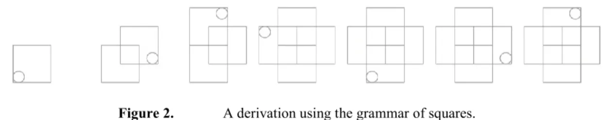
Let us consider the following example of a shape grammar with lines and circles as a vocabulary of shapes. The shape grammar of Figure 1 yields the derivation shown in Figure 2.
Figure 2. A derivation using the grammar of squares.
Each shape generated by the application of this grammar is obtained starting from the initial shape and repeatedly applying the shape grammar rule to the square with a circle in the left bottom corner. Each of the applications uses a different Euclidean transformation combining translation and rotation applied to the left side of the shape rule.
Note that the circle in the previous shape grammar prevents the achievement of crossed squares in all directions. It also blocks the application of the shape rule to the reached emergent smaller squares.
Within shape grammars emergence is a foundational feature mentioned and discussed by many researchers [Mit93, Sti94, Kni03]. Emergent shapes may be seen as shapes that are not added by shape rule applications, i.e. any shape that is not a shape t(B) added by a previous application of a shape rule AB.
The conventional shape grammar formalism employs labeled points as a way of controlling the application of shape rules during the design process. This control may avoid the application of particular Euclidean transformations or even completely block the application of one or more shape rules. Moreover, by using labeled points, a sequential programming style can be used to describe the design process. Shape rules with labeled points on their right hand side must be used before other shape rules with the same labeled points on their left hand side. This strategy has been used within shape grammars to generate a variety of designs [AgC98, Dua05, Hei94, Sti80a, Sti80b]. However, shape knowledge within these specific design applications is represented in a procedural and ad hoc way and is therefore too rigid for generic automation.
We believe that shape knowledge and procedural knowledge should be detached from each other if we want to obtain a framework for flexible design generation and quick design specification. Detaching this knowledge would facilitate convenient abstraction and modularization for algorithmic development. An approach for design
generation should thus provide convenient abstractions for representing shape knowledge, procedural knowledge and also the definition of other relevant application concepts.
As pointed out in [RBB14], design models and tools need to support expert knowledge specification in the form of design requirements that can be used to evaluate solutions or to guide the exploration or generation of designs. A designer should express design specifications not only by visual knowledge in the form of shape rules but also by logic requirements. A tool allowing such a design specification should then support evaluation of the requirements during the generation process.
The main feature of Alternative Shaper is to explicitly detach shape knowledge from procedural knowledge. This, together with the use of a nondeterministic process style perspective supports an exploratory and flexible specification of designs that may be generated according to design requirements.
3.
Alternative Shaper
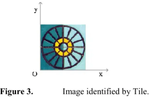
In Alternative Shaper [SaR13, SaE15] the emphasis is made on symbols, not on shapes. Each symbol may identify a different shape, starting from a set of basic shapes, whether they are dots, lines, geometric or solid shapes or even images, i.e. a square 2D image. In this paper we explore this last possibility. We foresee that the other possibilities may be explored in the same fashion. For instance, the identifier Tile may be associated with a square image of a tile from Maria Keil of Figure 3 defined in the respective coordinate system xOy. This image can assume a fixed size as in the grammar defined in Section 5 when it represents a modular part of a house.
Positioning a shape within a different coordinate system x’O’y’ (Figure 4) is represented by a pair (shape, transformation) specifying the transformation (translation, rotation, scale, etc.) required for positioning the coordinate system xOy associated to the defined shape into the new coordinate system x’O’y’. Note that each shape is represented by the identity transformation Id when the shape is defined and, in this case, the identity transformation may be omitted within the representation. Note also that, given a shape s and an Euclidean transformation t, (s,t) and t(s) represent the same shape. However, the first representation emphasizes the need for registering the Euclidean transformation applied to the original shape definition. Both notations will be used below.
Figure 3. Image identified by Tile.
For instance, in Figure 4 Tile is positioned into the coordinate system x’O’y’ by a scaling S(c,d) and rotation R()
followed by a translation T(a,b) and thus represented by (Tile, T(a,b)R()S(c,d)).
Formally, the set Transf of 2D Euclidean transformations is defined by:
Definition 1: 𝑇ℎ𝑒 𝑠𝑒𝑡 𝑇𝑟𝑎𝑛𝑠𝑓 𝑜𝑓 𝑎𝑙𝑙 2𝐷 𝐸𝑢𝑐𝑙𝑖𝑑𝑒𝑎𝑛 𝑡𝑟𝑎𝑛𝑠𝑓𝑜𝑟𝑚𝑎𝑡𝑖𝑜𝑛𝑠 𝑖𝑠 𝑖𝑛𝑑𝑢𝑐𝑡𝑖𝑣𝑒𝑙𝑦 𝑑𝑒𝑓𝑖𝑛𝑒𝑑 𝑏𝑦 1. 𝐼𝑑 𝑇𝑟𝑎𝑛𝑠𝑓, the identity transformation;
2. 𝑅(𝜃) 𝑇𝑟𝑎𝑛𝑠𝑓, 𝜃[0°, 360°], a rotation of o;
3. 𝑇(𝑣) 𝑇𝑟𝑎𝑛𝑠𝑓, 𝑣𝑅2, a translation on v; 4. 𝑆(𝑣) 𝑇𝑟𝑎𝑛𝑠𝑓, 𝑣𝑅2, a scale on v.
Figure 4. Positioning Tile into a new coordinate system x’O’y’. Using a matrix representation within a 2D homogeneous coordinate system, we have, 𝑇(𝑎, 𝑏) = [1 0 𝑎0 1 𝑏 0 0 1 ] 𝑅(𝜃) = [𝑠𝑒𝑛 𝜃𝑐𝑜𝑠 𝜃 −𝑠𝑒𝑛 𝜃 0𝑐𝑜𝑠 𝜃 0 0 0 1 ] 𝑆(𝑐, 𝑑) = [𝑐 0 00 𝑑 0 0 0 1 ]
Shape compositions may be represented by sets of shapes positioned in the same coordinate system. For instance, for a 1x1 unit Tile, the shape composition of two units Tile in Figure 5 is represented by {(𝑇𝑖𝑙𝑒, 𝑆(1/2,1/2)), (𝑇𝑖𝑙𝑒, 𝑇(1/2 − √2/4, 1/2 + √2/4) 𝑅(315°) 𝑆(1/2,1/2)}.
Figure 5. A shape composition of two units Tile.
Formally, given a vocabulary of identified basic shapes 𝑉 ≠ Ø, the set Shape of shape compositions can be defined as:
Definition 2: 𝑇ℎ𝑒 𝑠𝑒𝑡 𝑆ℎ𝑎𝑝𝑒 𝑜𝑓 𝑎𝑙𝑙 𝑠ℎ𝑎𝑝𝑒 𝑐𝑜𝑚𝑝𝑜𝑠𝑖𝑡𝑖𝑜𝑛𝑠 𝑖𝑠 𝑖𝑛𝑑𝑢𝑐𝑡𝑖𝑣𝑒𝑙𝑦 𝑑𝑒𝑓𝑖𝑛𝑒𝑑 𝑏𝑦 1. {𝑡(𝑆)} 𝑆ℎ𝑎𝑝𝑒,𝑆𝑉,𝑡𝑇𝑟𝑎𝑛𝑠𝑓;
2. 𝐼𝑓 𝑆𝐻1, 𝑆𝐻2 𝑆ℎ𝑎𝑝𝑒 𝑡ℎ𝑒𝑛 𝑆𝐻1 𝑆𝐻2 𝑆ℎ𝑎𝑝𝑒.
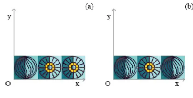
The same shapes positioned differently yields different shape compositions, as can be easily seen by shape {(𝑇𝑖𝑙𝑒, 𝑆(1/2,1/2)), (𝑇𝑖𝑙𝑒, 𝑇(1/2,1/2) 𝑅(45°) 𝑆(1/2,1/2)} of Figure 6 when compared to shape of Figure 5. However, different shapes may look similar given a suitable symmetry of the used image.
Figure 6. A diffent shape composition of two units Tile.
Using this representation and given two shape compositions A and B, A is a sub-shape of B if and only if (iff) all the shapes in A are also in B.
Definition 3: The subshape operation < : 𝑆ℎ𝑎𝑝𝑒 𝑆ℎ𝑎𝑝𝑒 𝑏𝑜𝑜𝑙𝑒𝑎𝑛 is defined by 𝐴 < 𝐵 𝑖𝑓𝑓 𝐴𝐵.
The formal model is easily extended with shape definitions such as 𝑆 = {𝑡1(𝑆1), … , 𝑡𝑘(𝑆𝑘)} for identifying elaborated shape compositions, e.g. 𝐹𝑖𝑟𝑠𝑡2𝑇𝑖𝑙𝑒𝑠 = {(𝑇𝑖𝑙𝑒, 𝑆(1/2,1/2)), (𝑇𝑖𝑙𝑒, 𝑇(1/2 − √2/4, 1/2 + √2/4)𝑅(315°) 𝑆(1/2,1/2)} and 𝑆𝑒𝑐𝑜𝑛𝑑2𝑇𝑖𝑙𝑒𝑠 = {(𝑇𝑖𝑙𝑒, 𝑆(1/2,1/2)), (𝑇𝑖𝑙𝑒, 𝑇(1/2,1/2)𝑅(45°)𝑆(1/2,1/2)}.
To obtain a shape according to Definition 2, when such defined shapes are positioned, the Euclidean transformations applied to the identifiers should be composed with the Euclidean transformations applied to the components, i.e 𝑡(𝑆) = {𝑡 ∘ 𝑡1(𝑆1), … , 𝑡 ∘ 𝑡𝑘(𝑆𝑘)}.
With this extension, the representation of shape compositions turns out to be a set of sets of positioned shapes. However, this representation could easily be flattened for comparing shape compositions using just the basic shapes. In this case, sub-shape operation of Definition 3 should be adapt to 𝐴 < 𝐵 iff 𝑓𝑙𝑎𝑡𝑡𝑒𝑛(𝐴) 𝑓𝑙𝑎𝑡𝑡𝑒𝑛(𝐵), for an more adequate defined operation 𝑓𝑙𝑎𝑡𝑡𝑒𝑛: 𝑆ℎ𝑎𝑝𝑒 𝑆ℎ𝑎𝑝𝑒.
In this approach, Shape Grammar Rules are represented by pairs of shape compositions. For instance, for a 1x1 unit Tile, the shape grammar rule of Figure 7 is represented by {(𝑇𝑖𝑙𝑒, 𝑆(1/2,1/2))} {(𝑇𝑖𝑙𝑒, 𝑆(1/2,1/ 2)), (𝑇𝑖𝑙𝑒, 𝑇(1/2 − √2/4, 1/2 + √2/4)𝑅(315°)𝑆(1/2,1/2))} or {(𝑇𝑖𝑙𝑒, 𝑆(1/2,1/2))} 𝐹𝑖𝑟𝑠𝑡2𝑇𝑖𝑙𝑒𝑠.
Figure 8. t=t2t1-1transforms shape t1(Tile) into shape t2(Tile).
Discovering a Euclidean transformation t such that t(A)<s for the application of a shape grammar rule AB is simply finding a transformation able to transform every shape of A into shapes within s. A Euclidean transformation
t able to transform shape 𝑡1(𝑖) into shape 𝑡2(𝑖) is easily obtained by 𝑡 = 𝑡2𝑡1−1 (see Figure 8, for i=Tile).
One main advantage of our approach is that it easily supports shape composition properties. Note that these properties may be used to define design objectives and characterize the control of design processes. Although it may be generalized in the usual way, in this paper we just use quantifications over identified basic shapes. The quantification allows the confirmation that some or all the shapes identified by A (AV) verify a specific property.
Definition 4: The set LF of all predicate formulas on shapes is inductively defined by
1. 𝑇𝑟𝑢𝑒 𝐿𝐹;
2. 𝑃(𝐴1, … , 𝐴𝑘) 𝐿𝐹 for every k-ary (𝑘 ≥ 0) atomic predicate P and every (𝐴1, … , 𝐴𝑘) 𝑆ℎ𝑎𝑝𝑒𝑘; 3. If 𝜑𝐿𝐹 then 𝜑𝐿𝐹;
4. If 𝜑1, 𝜑2𝐿𝐹 then (𝜑1𝜑2)𝐿𝐹; 5. If 𝜑1, 𝜑2𝐿𝐹 then (𝜑1𝜑2)𝐿𝐹; 6. If 𝜑𝐿𝐹, 𝐴𝑉 then 𝑎𝑙𝑙 (𝐴, 𝜑)𝐿𝐹 ; 7. If 𝜑𝐿𝐹, 𝐴𝑉 then some(𝐴, 𝜑)𝐿𝐹.
The interpretation of these formulas [End72] is based on the interpretation I(P,s) of each atomic predicate P within a shape composition s, that characterizes property P depending on number and the relative positions of shapes in s. For instance, the unary predicate eight, representing 8 occurrences of a given identified shape identifier within a shape composition, is interpreted by I(eight, s) = {𝑖| ⋕ {(𝑖, 𝑡)|𝑡𝑇𝑟𝑎𝑛𝑓 (𝑖, 𝑡) 𝑠} = 8}.
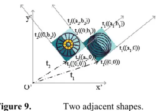
Note that certain interpretations are universal and do not depend on a specific shape composition. For instance the binary predicate next, representing the adjacency of a 𝑎1× 𝑏1 shape 𝑠1, positioned by transformation𝑡1,with a 𝑎2 × 𝑏2shape 𝑠2, positioned by transformation 𝑡2, is interpreted by I(next, s)= { (𝑠1, 𝑡1), (𝑠2, 𝑡2) | ∃ 𝑙1∈ {𝑙𝑖𝑛𝑒(𝑡1(0,0), 𝑡1(𝑎1, 0)), 𝑙𝑖𝑛𝑒(𝑡1(𝑎1, 0), 𝑡1(𝑎1, 𝑏1)), 𝑙𝑖𝑛𝑒(𝑡1(𝑎1, 𝑏1), 𝑡1(0, 𝑏1)), 𝑙𝑖𝑛𝑒(𝑡1(0, 𝑏1), 𝑡1(0,0)), ∃ 𝑙2∈ {𝑙𝑖𝑛𝑒(𝑡2(0,0), 𝑡2(𝑎2, 0)), 𝑙𝑖𝑛𝑒(𝑡2(𝑎2, 0), 𝑡2(𝑎2, 𝑏2)), 𝑙𝑖𝑛𝑒(𝑡2(𝑎2, 𝑏2), 𝑡2(0, 𝑏2)), 𝑙𝑖𝑛𝑒(𝑡2(0, 𝑏2), 𝑡2(0,0)), 𝑙1 𝑎𝑛𝑑 𝑙2 are collinear and share two points}}see Figure 9).
Figure 9. Two adjacent shapes.
Given an interpretation I of each atomic predicate P within a shape composition s, a Boolean valuation represents the truth value of each formula for a shape composition.
Definition 5: The Boolean valuation 𝑣: 𝐿𝐹 𝑆ℎ𝑎𝑝𝑒 𝑏𝑜𝑜𝑙𝑒𝑎𝑛 is recursively defined by 1. 𝑣(𝑇𝑟𝑢𝑒, 𝑠) = 𝑡𝑟𝑢𝑒;
2. 𝑣(𝑃(A1, …,Ak), 𝑠) = 𝑡𝑟𝑢𝑒 iff (A1, …,Ak)𝐼(𝑃, 𝑠);
3. 𝑣(𝜑, 𝑠) = 𝑡𝑟𝑢𝑒 iff 𝑣(𝜑, 𝑠) = 𝑓𝑎𝑙𝑠𝑒;
4. 𝑣((𝜑1 𝜑2), 𝑠) = 𝑡𝑟𝑢𝑒 iff 𝑣(𝜑1, 𝑠) = 𝑡𝑟𝑢𝑒 𝑎𝑛𝑑 𝑣(𝜑2, 𝑠) = 𝑡𝑟𝑢𝑒; 5. 𝑣((𝜑1 𝜑2), 𝑠) = 𝑡𝑟𝑢𝑒 iff 𝑣(𝜑1, 𝑠) = 𝑡𝑟𝑢𝑒 𝑜𝑟 𝑣(𝜑2, 𝑠) = 𝑡𝑟𝑢𝑒;
6. 𝑣(𝑎𝑙𝑙(𝐴,𝜑), 𝑠) = 𝑡𝑟𝑢𝑒 iff 𝑣(𝜑[𝐴𝑡(𝐴)]), 𝑠) = 𝑡𝑟𝑢𝑒, ∀𝑡 ∈ 𝑇𝑟𝑎𝑛𝑠𝑓 𝑡(𝐴) < 𝑠; 7. 𝑣(𝑠𝑜𝑚𝑒(𝐴,𝜑), 𝑠) = 𝑡𝑟𝑢𝑒 iff 𝑣(𝜑[𝐴𝑡(𝐴)], 𝑠) = 𝑡𝑟𝑢𝑒, ∃𝑡 ∈ 𝑇𝑟𝑎𝑛𝑠𝑓 𝑡(𝐴) < 𝑠;
In the previous definition, 𝜑[𝐴𝑡(𝐴)] is the formula obtained from by uniform substitution of each free occurrence of A in by t(A). For instance, 𝑛𝑒𝑥𝑡(𝑇𝑖𝑙𝑒, (𝑇𝑖𝑙𝑒, 𝑖))[𝑇𝑖𝑙𝑒(𝑇𝑖𝑙𝑒, 𝑇(1/2,1/2)𝑅(45°))] is 𝑛𝑒𝑥𝑡((𝑇𝑖𝑙𝑒, 𝑇(1/2,1/2) 𝑅(45°)), (𝑇𝑖𝑙𝑒, 𝑖)).
Note that, given a formula referring a shape A, the truth value within a shape s of the formulas some(A,) and all(A,) depends on all sub-shapes t(A) of s. More precisely, some(A,) (resp. all(A,)) is true if and only if there is
a (resp. for all) sub-shapes t(A) of s the formula is true for t(A) in s, i.e., 𝜑[𝐴𝑡(𝐴)] is true in s.
As previously mentioned, our approach detaches procedural knowledge from shape knowledge using procedural notions that capture sequences, alternatives and tests for the application of shape grammar rules to the initial shape during design process. Thus we define the set of processes – Proc - using Definition 6.
Definition 6: The set Proc is inductively define by
1. nothing Proc (empty rule process);
2. If p1,p2Proc then (p1orp2)Proc (alternative rule process);
3. If p1,p2Proc then (p1;p2)Proc (sequential rule process);
4. Verify(𝜑)Proc, 𝜑LF (test rule process);
5. ABProc, A,BShape (general shape rule).
We may also extend the previous definition by using additional identifiers to represent elaborated processes composed by other processes, e.g. 𝑠𝑟1 = {(𝑇𝑖𝑙𝑒, 𝑆(1/2,1/2))} 𝐹𝑖𝑟𝑠𝑡2𝑇𝑖𝑙𝑒𝑠 , 𝑠𝑟2 = {(𝑇𝑖𝑙𝑒, 𝑆(1/2,1/ 2))} 𝑆𝑒𝑐𝑜𝑛𝑑2𝑇𝑖𝑙𝑒𝑠 and 𝑟𝑜𝑡𝑎𝑡𝑒𝑇𝑖𝑙𝑒𝑠1 = (𝑠𝑟1; (𝑠𝑟1; (𝑠𝑟1; (𝑠𝑟1; (𝑠𝑟1; (𝑠𝑟1; 𝑠𝑟1)))))).
Shapes generated by the application of shape rule processes are characterized by the following function
Definition 7: 𝑇ℎ𝑒 𝑓𝑢𝑛𝑐𝑡𝑖𝑜𝑛 𝑒𝑥𝑒𝑐: 𝑃𝑟𝑜𝑐 𝑆ℎ𝑎𝑝𝑒 2𝑆ℎ𝑎𝑝𝑒 𝑖𝑠 𝑟𝑒𝑐𝑢𝑟𝑠𝑖𝑣𝑒𝑙𝑦 𝑑𝑒𝑓𝑖𝑛𝑒𝑑 𝑏𝑦 1. 𝑒𝑥𝑒𝑐(𝑛𝑜𝑡ℎ𝑖𝑛𝑔, 𝑠) = {𝑠}; 2. 𝑒𝑥𝑒𝑐((𝑝1𝑜𝑟𝑝2), 𝑠) = 𝑒𝑥𝑒𝑐(𝑝1, 𝑠) 𝑒𝑥𝑒𝑐(𝑝2, 𝑠); 3. 𝑒𝑥𝑒𝑐((𝑝1; 𝑝2), 𝑠) = ⋃𝑢∈𝑒𝑥𝑒𝑐(𝑝1,𝑠)𝑒𝑥𝑒𝑐(𝑝2, 𝑢); 4. 𝑒𝑥𝑒𝑐(𝑉𝑒𝑟𝑖𝑓𝑦(𝜑), 𝑠) = {𝑠 | 𝑣(𝜑, 𝑠) = 𝑡𝑟𝑢𝑒}; 5. 𝑒𝑥𝑒𝑐(𝐴𝐵, 𝑠) = {𝑠– {𝑡(𝐴)}{𝑡(𝐵)}|𝑡𝑇𝑟𝑎𝑛𝑠𝑓 𝑡(𝐴) < 𝑠}.
Processes apply shape rules repeatedly to the intermediate shapes so far obtained, according to the order sequentially established in the process.The test process checks if certain conditions are met. The shape grammar rules and the alternative compositions of the processes offer the possibility to generate a shape composition among different alternatives. This means that we follow a non-deterministic perspective in the characterization of design processes.
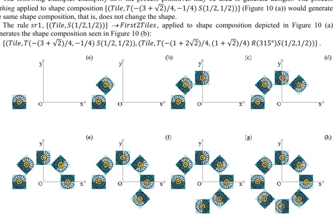
The following examples exemplify how the process primitives may be used to generate designs. The process
nothing applied to shape composition {(𝑇𝑖𝑙𝑒, 𝑇(−(3 + √2)/4, −1/4) 𝑆(1/2, 1/2))} (Figure 10 (a)) would generate the same shape composition, that is, does not change the shape.
The rule 𝑠𝑟1, {(𝑇𝑖𝑙𝑒, 𝑆(1/2,1/2))} 𝐹𝑖𝑟𝑠𝑡2𝑇𝑖𝑙𝑒𝑠, applied to shape composition depicted in Figure 10 (a) generates the shape composition seen in Figure 10 (b):
{(𝑇𝑖𝑙𝑒, 𝑇(−(3 + √2)/4, −1/4) 𝑆(1/2, 1/2)), (𝑇𝑖𝑙𝑒, 𝑇(−(1 + 2√2)/4, (1 + √2)/4) 𝑅(315°)𝑆(1/2,1/2))} .
Figure 10. Designs generated by process rotateTiles1 applied to shape composition {(𝑇𝑖𝑙𝑒, 𝑇(−(3 +
√2
)/4, 1/4) 𝑆(1/2, 1/2))}.The same rule - 𝑠𝑟1 - applied to this last shape composition, i.e. (𝑠𝑟1; 𝑠𝑟1), applied to the initial shape would generate again the same compositions if applied to shape composition {(𝑇𝑖𝑙𝑒, 𝑇(−(3 + √2)/4, −1/4) 𝑆(1/2, 1/2))} or would generate {(𝑇𝑖𝑙𝑒, 𝑇(−(3 + √2)/4, −1/4) 𝑆(1/2, 1/2)) ,
(𝑇𝑖𝑙𝑒, 𝑇(−(1 + 2√2)/4, (1 + √2)/4)𝑅(315°)𝑆(1/2, 1/2)) , (𝑇𝑖𝑙𝑒, 𝑇(−1/4, (3 + √2)/4)𝑅(270°) 𝑆(1/ 2,1/2))} (Figure 10 (c)) if applied to shape composition {(𝑇𝑖𝑙𝑒, 𝑇(−(1 + √2)/4, (1 + √2)/ 4) 𝑅(315°)𝑆(1/2, 1/2))}. The possibility to generate one shape composition among different alternatives gives an idea of the non-deterministic perspective considered in the Alternative Shaper model.
Not surprisingly, the process 𝑟𝑜𝑡𝑎𝑡𝑒𝑇𝑖𝑙𝑒𝑠1 applied to shape composition {(𝑇𝑖𝑙𝑒, 𝑇(−(3 + √2)/4, −1/ 4) 𝑆(1/2, 1/2))} would generate one of the designs of Figure 10 (with the exception of the first one). However, (𝑟𝑜𝑡𝑎𝑡𝑒𝑇𝑖𝑙𝑒𝑠1; 𝑉𝑒𝑟𝑖𝑓𝑦(𝑒𝑖𝑔ℎ𝑡(𝑇𝑖𝑙𝑒))) applied to shape composition {(𝑇𝑖𝑙𝑒, 𝑇(−(3 + √2)/4, −1/4) 𝑆(1/2, 1/2))} would just generate the design Figure 10 (h). This gives an idea of the use of the test process for selecting specific designs. This control of design generation could also be made using conditional shape rules to be discussed in the next section. Moreover, repetitions of previous obtained designs could also be avoided using strategies like the last one or using conditional shape rules.
Finally, the alternative process (𝑠𝑟1𝑜𝑟𝑠𝑟2) applied to shape composition {(𝑇𝑖𝑙𝑒, 𝑆(1/2,1/2)} would generate one of the designs 𝐹𝑖𝑟𝑠𝑡2𝑇𝑖𝑙𝑒𝑠 or 𝑆𝑒𝑐𝑜𝑛𝑑2𝑇𝑖𝑙𝑒𝑠, once again in a non-deterministic way.
Processes are considered equal if they generate the same shapes, i.e.,
Definition 8: 𝐺𝑖𝑣𝑒𝑛 𝑝𝑟𝑜𝑐𝑒𝑠𝑠𝑒𝑠 𝑝1,𝑝2𝑃𝑟𝑜𝑐,𝑝1=𝑝2𝑖𝑓𝑓 𝑒𝑥𝑒𝑐(𝑝1, 𝑠) = 𝑒𝑥𝑒𝑐(𝑝2, 𝑠) 𝑓𝑜𝑟 𝑒𝑣𝑒𝑟𝑦 𝑠𝑆ℎ𝑎𝑝𝑒. On the other hand, some of the usual conventional commands can be written using the previous ones and we may consider the following abbreviations:
𝑖𝑓(𝜑, 𝑝1, 𝑝2) = ((𝑣𝑒𝑟𝑖𝑓𝑦(𝜑); 𝑝1) 𝑜𝑟 (𝑣𝑒𝑟𝑖𝑓𝑦(𝜑); 𝑝2)) 𝑤ℎ𝑖𝑙𝑒(𝜑, 𝑝) = 𝑖𝑓(𝜑, (𝑝; 𝑤ℎ𝑖𝑙𝑒(𝜑, 𝑝)), 𝑛𝑜𝑡ℎ𝑖𝑛𝑔)
We may now define formally a spatial grammar in the context of Alternative Shaper with the previous introduced concepts.
Definition 9: 𝐴 𝑠𝑝𝑎𝑡𝑖𝑎𝑙 𝑔𝑟𝑎𝑚𝑚𝑎𝑟 𝑖𝑠 𝑎 3 𝑡𝑢𝑝𝑙𝑒 𝐺 = (𝑉, 𝑠0, 𝑝) 𝑤ℎ𝑒𝑟𝑒: 1. 𝑉 ≠ Ø 𝑖𝑠 𝑡ℎ𝑒 𝑣𝑜𝑐𝑎𝑏𝑢𝑙𝑎𝑟𝑦 𝑜𝑓 𝑖𝑑𝑒𝑛𝑡𝑖𝑓𝑖𝑒𝑑 𝑏𝑎𝑠𝑖𝑐 𝑠ℎ𝑎𝑝𝑒𝑠; 2. 𝑠0𝑆ℎ𝑎𝑝𝑒 𝑖𝑠 𝑡ℎ𝑒 𝑖𝑛𝑖𝑡𝑖𝑎𝑙 𝑠ℎ𝑎𝑝𝑒;
3. 𝑝𝑃𝑟𝑜𝑐 𝑖𝑠 𝑡ℎ𝑒 𝑟𝑢𝑙𝑒 𝑝𝑟𝑜𝑐𝑒𝑠𝑠.
Given a spatial grammar G = (V, s0, p), the language L(G) of all designs generated by G is the set of
the shapes that may be obtained starting from the initial shape s0 and applying shape rules to the obtained
shapes according to the process p.
Definition 10: 𝐺𝑖𝑣𝑒𝑛 𝑎 𝑠𝑝𝑎𝑡𝑖𝑎𝑙 𝑔𝑟𝑎𝑚𝑚𝑎𝑟 𝐺 = (𝑉, 𝑠0, 𝑝), 𝐿(𝐺) = {𝑠| 𝑠𝑒𝑥𝑒𝑐(𝑝, 𝑠0)}.
For instance, the G1 = ({Tile},{(Tile,T(-(3+ √2 )/4,-1/4) S(1/2,1/2))},(nothing or ((sr1;(sr1;(sr1;(sr1;(sr1; (sr1;sr1))))))); Verify(eight(Tile))), would generate the language L(G1) = {{(3+ √2 )/4,-1/4)S(1/2, 1/2))}, {(3+ √2 )/4,-1/4)S(1/2,1/2)), (Tile,T(-(1+2 √2 )/4,(1+ √2 )/4)R(315ᵒ)S(1/2,1/2)), (Tile,T(-1/4, (3+ √2 )/4)R(270ᵒ)S(1/2,1/2)),
(Tile,T((1+2√2)/4,(1+√2)/4)R(225ᵒ)S(1/2,1/2)), (Tile,T((3+2√2) /4,1/4)R(180ᵒ)S(1/2,1/2)), (Tile,T((1+2√2)/4,-(1+√2)/4) R(135ᵒ)S(1/2,1/2)), (Tile,T(1/4,-(3+√2)/4) R(90ᵒ) S(1/2,1/2)), (Tile,T(-(1+2√2)/4,-(1+√2)/4)R(45ᵒ)S(1/2,1/2))}} (Figure 10 (a) and Figure 10 (h)).
Given a spatial grammar G = (V, s0, p), the language L(G) of all designs generated by G may be
produced by a computer program by forward chaining using some operational preference in the choice of the alternatives. Each time a test process Verify fails or a shape grammar rule fails to apply, the system backtracks trying to build a different solution.
4.
Conditional Shape
RulesAs in many other applications of shape grammars for the characterization of designs [Dua05, ElD12, GAK08], we also find out the need to use conditional shape rules, i.e. shape rules with a logical pre-condition restricting the rule application. However, these types of rules are informal extensions of the original concept of Shape Rule characterized by Stiny and Gips [StG72] and thus need further formal clarification.
A general shape grammar rule AB applies to a shape s whenever there is an Euclidean transformation t such that t(A)<s. For each such Euclidean transformation t, the result of the rule application is the shape obtained by replacing the sub-shape t(A) of s by the shape t(B). Since there may be many instances of A on s, in order to restrict the application of the rule AB to each instance t(A) satisfying a certain condition, a conditional shape rule is needed as well as a way to refer to a shape t(C) on the condition of the rule during a specific application of the shape spatial rule.
On the one hand, for dealing with conditional shape rules, consider the additional inductive rule in the definition of the set Proc of Definition 6:
6. 𝐴𝐵 𝑖𝑓 𝜑𝑃𝑟𝑜𝑐,𝐴, 𝐵𝑆ℎ𝑎𝑝𝑒 𝜑𝐿𝐹+ (𝑐𝑜𝑛𝑑𝑖𝑡𝑖𝑜𝑛𝑎𝑙 𝑠ℎ𝑎𝑝𝑒 𝑟𝑢𝑙𝑒).
On the other hand, the use of the relative positioning shapes matched(C) in such conditions (CShape) supports this important additional expressivity. Thus, in the previous definition, LF+ differs
from LF proposed in Definition 4 with respect to the possible use of the relative positioning shapes
matched(A) (AShape) in the first inductive rule:
1. 𝑃(𝐴1, … , 𝐴𝑘)𝐿𝐹, 𝑓𝑜𝑟 𝑒𝑣𝑒𝑟𝑦 𝑘 − 𝑎𝑟𝑦 (𝑘 ≥ 0) 𝑎𝑡𝑜𝑚𝑖𝑐 𝑝𝑟𝑒𝑑𝑖𝑐𝑎𝑡𝑒 𝑃
𝑎𝑛𝑑 𝑒𝑣𝑒𝑟𝑦 (𝐴1, … ,𝐴𝑘) (𝑆ℎ𝑎𝑝𝑒{𝑚𝑎𝑡𝑐ℎ𝑒𝑑(𝐴)|𝐴𝑆ℎ𝑎𝑝𝑒})𝑘
Let us consider the additional inductive rule in the recursive definition of the function exec of Definition 7:
6. 𝑒𝑥𝑒𝑐(𝐴𝐵 𝑖𝑓 𝜑, 𝑠) = {𝑠– {𝑡(𝐴)}{𝑡(𝐵)}| 𝑡𝑇𝑟𝑎𝑛𝑠𝑓 𝑡(𝐴) < 𝑠 𝑣(𝑡(𝜑), 𝑠) = 𝑡𝑟𝑢𝑒} In the new definition, t() represents the formula obtained from by the previous substitution of each relative positioning shapes. Formally:
Definition 11: 𝑇ℎ𝑒 𝑓𝑢𝑛𝑐𝑡𝑖𝑜𝑛 ( ): 𝑇𝑟𝑎𝑛𝑠𝑓 𝐿𝐹+ 𝐿𝐹 𝑖𝑠 𝑟𝑒𝑐𝑢𝑟𝑠𝑖𝑣𝑒𝑙𝑦 𝑑𝑒𝑓𝑖𝑛𝑒𝑑 𝑏𝑦 1. t(True) = true; 2. t(P(A)) = P(A); 3. t(P(matched(A))) = P(t(A)); 4. t(φ) = t(φ); 5. t((𝜑1𝜑2)) = (t(𝜑1) t(𝜑2)); 6. t((𝜑1𝜑2)) = (t(𝜑1) t(𝜑2)); 7. t(all(A, 𝜑)) = all(A, t(𝜑)); 8. t(some(A, 𝜑)) = some(A, t(𝜑)).
Let us consider the following example of a conditional shape rule in Figure 11 that may be applied to a
Tile if it is not adjacent to a 𝑇𝑖𝑙𝑒2, i.e. {(Tile,S(1/2,1/2))} {(Tile2,S(1/2,1/2)) if some(Tile2, next(matched((Tile, S(1/2,1/2))),Tile2)).
Figure 11. A conditional shape grammar rule.
When applied to shape composition 𝑠 = {(𝑇𝑖𝑙𝑒2, 𝑆(1/2, 1/2)), (𝑇𝑖𝑙𝑒, 𝑇(1/2,0)𝑆(1/2,1/ 2)), (𝑇𝑖𝑙𝑒, 𝑇(1,0)𝑆(1/2,1/2))} (Figure 12 (a)), there are two Euclidean transformations t such that t({(Tile,S(1/2,1/2))})<s: t1 = T(1/2,0) and t2 = T(1,0).
Figure 12. Application of the conditional shape grammar rule.
However, for transformation t1 matched((Tile,S(1/2,1/2))) = (Tile,T(1/2,0)S(1/2,1/2)) and
v(next((Tile,T(1/2,0)S(1/2,1/2)),(Tile2,S(1/2,1/2)),s) = true and thus the shape rule condition fails. For transformation t2, matched((Tile, S(1/2,1/2))) = (Tile,T(1,0) S(1/2,1/2)) and v(next((Tile,T(1,0) S(1/2,1/2)),
(Tile2,S(1/2, 1/2)),s) = false and thus the shape rule may be applied to s obtaining {(Tile2,S(1/2,1/2)),(Tile, T(1/2,0)S(1/2,1/2)),(Tile2,T(1,0)S(1/2,1/2))} (Figure 12 (b)).
Note that general shape rules are conditional shape rules with conditions always true, i.e. AB = AB if True. Note also that in general AB if ≠ Verify();AB only due to the fact that shape rule conditions use logic formulas with relative positioning shapes that are absent within logic formulas used in test processes. However, the equality holds for conditions belonging to LF.
Theorem 1: 𝐴𝐵 𝑖𝑓 𝜑 = 𝑉𝑒𝑟𝑖𝑓𝑦(𝜑); 𝐴𝐵,𝜑𝐿𝐹. Proof: straightforward, since = t() for LF.
Turning back to the design Figure 10 (h) generated by the process (rotateTiles1;Verify(eight(Tile)))
applied to shape composition {(𝑇𝑖𝑙𝑒, 𝑇(−(3 + √2)/4, −1/4)𝑆(1/2,1/2))}, it could be obtained by the process 𝑟𝑜𝑡𝑎𝑡𝑒𝑇𝑖𝑙𝑒𝑠2 = (𝑠𝑟3; (𝑠𝑟3; (𝑠𝑟3; (𝑠𝑟3; (𝑠𝑟3; (𝑠𝑟3; 𝑠𝑟3)))))) applied to the same shape composition, but using now the conditional shape rule 𝑠𝑟3 = {(𝑇𝑖𝑙𝑒, 𝑆(1/2,1/2))} {(𝑇𝑖𝑙𝑒, 𝑆(1/2,1/ 2)), (𝑇𝑖𝑙𝑒, 𝑇(1/2,1/2)𝑅(45ᵒ)𝑆(1/2,1/2)} 𝑖𝑓 𝑒𝑥𝑖𝑠𝑡𝑠( 𝑚𝑎𝑡𝑐ℎ𝑒𝑑((𝑇𝑖𝑙𝑒, 𝑇(1/2,1/2)𝑅(45º) 𝑆(1/2,1/ 2))) and considering the unary predicate exists, representing that a given shape w occurs within a shape composition, interpreted by 𝐼(𝑒𝑥𝑖𝑠𝑡𝑠, 𝑠) = {𝑤|𝑤𝑠}. Note that sr3 is sr2 with the application of an additional condition avoids the production of already obtained designs.
Operationally, there is a big advantage in considering the last alternative since it avoids repetitions of previous obtained designs during the generation process.
These examples illustrate the level of additional control available in Alternative Shaper model, detaching shape knowledge from procedural knowledge.
5.
Example of DesignA workbench automating the Alternative Shaper model has been implemented in SWI-prolog to explore a depth first search strategy of the design solution space. This first tool has been used for producing house layouts in a constructive modular system with wooden modules [SaR13, SaE15] and producing house layouts of mass-customized wooden single family houses [KSA16].
House layouts are guided by a set of design principles representing the spatial relations that should be fulfilled according to correct housing standards, the designer’s language of design and specific customers’ needs. The following rules represent an attempt to explicitly characterize one floor plan design principles that may be used in the context of the design system proposed in [KSA16]:
1. Privacy Rules – there are 3 main areas: entrance, semi-public and private;
2. Area Constitution Rules – the entrance area comprises a vestibule, a technical room, a garage, a toilet and a storage; the semi-public area comprises a home office, a kitchen, a dining room and a living room; the private area comprises a double bedroom, one or two single bedrooms and a bathroom;
3. Area Positioning Rules – areas should be placed from the entrance into deeper in the house; the public area should be placed in the front corner; the private area should be placed in the back corner; 4. Room Positioning Rules – the rooms are placed freely respecting the following principles:
4.2 the vestibule should be placed next to the garage;
4.3 the toilet and the technical room should be placed next to the garage;
4.4 the kitchen should be placed at the front corner, or next to dining room, or next to the home office;
4.5 the dining room should be placed in the front corner or next to the kitchen;
4.6 the living room should be placed in the front corner, or next to the kitchen, or next to the dining room;
4.7 the home office should be placed in the front corner or next to the living room;
4.8 the bathroom should be placed next to the double bedroom or next to a single bedroom; 4.9 one double bedroom and one single bedroom are placed in the back corner.
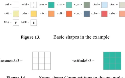
Below is a sketch of the application of the Alternative Shaper approach in the representation of this design system. The identifier explained in section 3 was here used as a color square that represents a part of the house layout. Depending on the type and size of room different color and number of squares are used, e.g. a Vestibule is composed by nine blue squares (Figure 14). Each square represents a module of 0.6x0.6m size.
Figure 13. Basic shapes in the example
Figure 14. Some shape Compositions in the example.
Using the basic shapes of Figure 13 to represent front and back markers (fron and back), empty space and house ridge (cell and wrid) and 0.6x0.6m cells for different room occupation – vestibule, garage, technical room, home office, hall, living room, dining room, kitchen, toilet, bathroom, single bedroom and double bedroom (respectively, cves, cgar, ctec, coff, chal, cliv, cdin, ckit, ctoi, cbat, csbe and cdbe), the following shape compositions of Figure 14 are represented respectively by
basement3x3 = {(cell,Id), (cell,T(0.6,0)), (cell,T(1.2,0)), (cell,T(0,0.6)), (cell,T(0.6,0.6)), (cell,T(1.2,0.6)),(cell,T(0,1.2)), (cell,T(0.6,1.2)), (cell, T(1.2, 1.2))} and
vestibule3x3 = {(cves,Id), (cves,T(0.6,0)), (cves,T(1.2,0)), (cves,T(0,0.6)), (cves,T(0.6,0.6)), (cves, T(1.2,0.6)), (cves,T(0,1.2)), (cves,T(0.6,1.2)), (cves, T(1.2,1.2))}.
Given the dimensions of the house and respective rooms, shape rules are considered for occupying an initial grid of empty cells.
Figure 15. A conditional shape grammar rule.
For instance, for a 3x3 vestibule, the following conditional shape grammar rule of Figure 15 is represented by
placeVestibule = basement3x3 vestibule3x3
if some( fron, next(matched(basement3x3),fron))
which condition characterizes that vestibule should be placed on the front of the house.
The following process describes steps for producing house layout solutions according to the design principles rules:
home = placeBasement; placeEntrance; placeSemipublic; placePrivate ; verify(homeRestrictions).
placeEntrance = placeVestibule; placeGarage; placeTechRoomandToilet.
placeSemipublic = placeHomeOffice and placeKitchen and placeDiningRoom and placeLivingRoom.
placePrivate = placeDoubleBedroom and placeSingleBedrooms and placeBathroom. placeSingleBedRooms = placeSingleBedRoom or placeSingleBedRoomwithHall.
The main process home characterizes the mentioned one floor plan design sequence. PlaceGarage, placeHomeOffice, placeTechRoomandToilet, placeKitchen, placeDiningRoom, placeLivingRoom, placeBathroom, placeDoubleBedroom, placeSingleBedroom and placeSingleBedRoomwithHall are shape grammar rules similar to the previous one.
Note that, for economy of space, in the previous formalization we use processes of the form (p1 and
p2) for denoting all the alternative sequential processes with shape rules of p1 and shape rules of p2, i.e. an
interleaving between p1 and p2.
The mentioned one floor plan design principles are characterized by the following logical formula identified by homeRestrictions.
homeRestrictions = (next(vestibule, garage) next(toilet, garage) next(technicalRoom, garage) (next(fron, homeOfice) next(fron, homeOfice) next(fron, homeOfice)) (next(diningRoom, fron) next(dinningRoom, kitchen) (next( homeOfice, fron)
next(homeOfice, livingRoom)) (next(bathRoom, doubleBedroom) next(bathRoom, singleBedroom)) some(doubleBedroom, next(doubleBedroom, back)) some(singleBedroom, next(singleBedroom, back)) (next( kitchen, fron) next(kitchen, dinningRoom) next(kitchen, homeOfice)) (next(livingRoom,fron) next(livingRoom, kitchen) next(livingRoom, dinningRoom)).
Note that, within the formalization of the previous restriction, vestibule, technicalRoom, garage, homeOfice, toilet, kitchen, diningRoom, livingRoom, doubleBedroom, singleBedroom, and bathroom identify the exact positioned shapes of the respective rooms. Without such identifiers, the exact positioned shapes must be identified by existential quantifiers, e.g., instead of next(vestibule,garage) we must write some(vestibule, some(garage, next(vestibule, garage))).
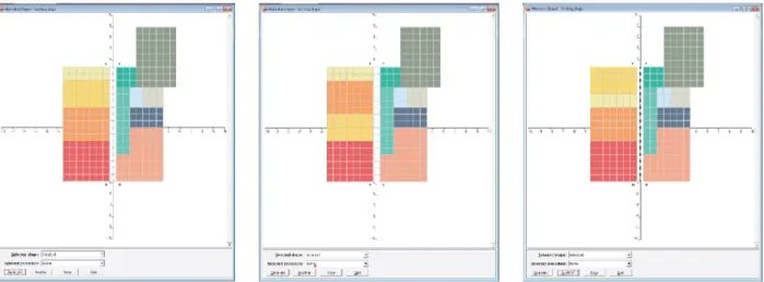
For a 17x14 house, the generation starts using the initial shape composition basement17x14 of 17x14 empty cells with front and back markers. The solutions of Figure 14 exemplify the generation process of house layouts fulfilling the design rules present so far for a 17x14 house with the following rooms and dimensions: 3x3 vestibule, 3x3 technical room, 9x6 garage, 3x2 toilet, 3x3 storage, 2x7 kitchen, 4x7 dining room, 5x7 living room, 4x7 double bedroom, 4x7 single bedroom, 4x7 single bedroom with hall and 3x5 bathroom.
Figure 16. Example of generated designs of a 17x14 house
The last process Verify(homeRestrictions) of the main process home select among all the designs those who verify the design principles. In such a layout only those three possibilities exist. Operationally, the searching process could be optimized if those design principles where adopted within conditions of conditional shape grammar rules.
6.
Conclusionsintention of providing easy design specification and fully automatic design generation. Alternative Shaper differs from conventional shape grammars with respect to emphasis being made on symbols instead of on shapes. This allows for an exhaustive use of identifiers for representing shapes and easily supports shape properties by using predicates relating those symbols. Alternative Shaper differs also on the detachment of procedural knowledge and shape knowledge and facilitates convenient abstraction and modularization for algorithmic development.
The model herein presented is further extended with conditional shape rules to increase additional expressivity and additional control for operationalizing the searching of design solutions within an exponential search space.
However, there are other issues that need further research, namely: 1. a complete development of a case study in order to find out approach limitations and propose other convenient abstractions; 2. study of an appropriate representation of parametric shapes; 3. study of appropriate computational forms for the representation of shapes and processes in order to avoid employing intractable algorithms.
For the purpose of the designs we want to generate, emergence is not the main issue in this model. Without any further mathematical machinery, the formalization of the sub-shape operation proposed in definition 3 does not allow the detection of emergent sub-shapes. However, we believe that the introduction of a shape hierarchy as well as an equality operation on shape compositions allows this approach to surpass this limitation in the same fashion that the maximal line form does by presenting an alternative representation of the same shapes. There are various possibilities for defining sub-shape operation in this approach. For instance, given two shape compositions A and B: A<B iff A’=A B’=B such that A’B’. This possibility proposes finding a common representation for shapes to which the sub-shape operation may apply, in the same fashion of maximal line representation proposed by Stiny [Sti80a], but not necessarily a canonical form in the bottom of the hierarchy of shapes. A. This is also a topic for further research.
Acknowledgements
The authors wish to thank the anonymous referees for their suggestions and criticisms on the submitted version of this paper.
This research has been carried out under research centre ISTAR-IUL (UID/MULTI/0446/2013). References
[AgC98] Agarwal, M. and Cagan, J.: A blend of different tastes: the language of coffeemakers. Environment and Planning B, 25, pp. 205-226, 1998.
[ATS16] Almeida, A., Taborda, B., Santos, F., Kwiecinski, K. and Eloy, S.: A genetic algorithm application for automatic layout design of modular residential homes. Proc. IEEE International Conference on Systems, Man, and Cybernetics, SMC2016, 2016.
[BDS10] Beirão, J., Mendes, G., Duarte, J. and Stouffs, R.: Implementing a Generative Urban Design Model. Grammar-based patterns for urban design. Proc. 28th conference on eCAADe, 28, pp. 265-274, 2010.
[Cha10] Chase, S.C.: Shape grammar implementations: the last 36 years (Shape grammar implementation: from theory to useable software). Presentation in Design Computing and Cognition workshop, Stuttgart, 2010.
[Cha04] Chau, H.H.: Evaluation of a 3D Shape Grammar Implementation. J.S. Gero (ed.), Design Computation and Cognition ’04, pp. 357-376, 2004.
[DRS07] Duarte, J.P., Rocha, J.M. and Soares, G.D.: Unveiling the Structure of the Marrakech Medina: A Shape grammar and an Interpreter for Generating Urban Form. Artificial Intelligence for Engineering Design, Analysis and Manufacturing, 21, pp. 317-349, 2007. [Dua05] Duarte, J.P.: A Discursive Grammar for Customizing Mass Housing: the case of Siza's
houses at Malagueira. Automation in Construction, 14(2), Elsevier Science, pp. 265-275, 2005.
[ElD12] Eloy, S. and Duarte, J.P.: A transformation grammar-based methodology for housing rehabilitation. Design Computing and Cognition, DCC’12, J.S. Gero (ed), Springer, 2012 [End72] Enderton, H.B.: A Mathematical Introduction to Logic. Academic Press, 1972.
[Fle87] Flemming. U.: More than the sum of its parts: the grammar of Queen Anne houses. Environment and Planning B, 14, pp. 323-350, 1987.
[Gip99] Gips, J.: Computer Implementation of Shape Grammars. In Workshop on Shape
Computation (pp. 1–11), 1999. Retrieved from http://www.shapegrammar.org/implement.pdf
[GAK08] Grobler, F., Aksamija, A., Kim, H., Krishnamurti, R. and Hickerson, C.: Ontologies and Shape Grammars: Comunication between Knowledge-Based and Generative Systems. Springer Science + Business Media B.V., pp. 23-80, 2008.
[GrE11] Grasl, T. and Economou, A.: GRAPE: using graph grammars to implement shape grammars. Proc. of the 2011 Symposium on Simulation for Architecture and Urban Design, 21-28, 2011.
[GrE13] Grasl, T. and Economou, A.: From topologies to shapes: parametric shape grammars implemented by graphs. Environment and Planning B: Planning and Design, 40, pp. 905-922, 2013.
[Hei94] Heisserman, J.: Generative Geometric Design. IEEE Computer Graphics and Applications, 14, pp. 37-45, 1994.
[Jow06] Jowers, I.: Computation with curved shapes:Towards freeform shape generation in design. PhD thesis, The Open University, 2006.
[Kni89] Knight, T.W.: Transformations of De Stijl art: the paintings of Georges Vantongerloo and Fritz Glarner. Environment and Planning B, 16, pp. 51-98, 1989.
[Kni93] Knight, T.W.: Color Grammars: the Representation of Form and Color in Design. Leonardo, 26,pp. 117-124, 1993.
[Kni03] Knight, T.: Computing with Emergence. Environment and Planning B: Planning and Design, 30, pp. 125-155, 2003.
[KoE81] Koning, G. and Eisenberg, J.: The language of the prairie: Frank Lloyd Wright’s prairie houses. Environment and Planning B, 8, pp. 295-323, 1981.
[Kri80] Krishnamurti, R.: The arithmetic of shapes. Environment and Planning B, 7, pp. 463-484, 1980.
[Kri81] Krishnamurti, R.: The construction of shapes. Environment and Planning B, 8, pp. 5-40, 1981.
[Kri92] Krishnamurti, R.: The maximal representation of a shape. Environment and Planning B, 19, pp. 267-288, 1992.
[KrS93] Krishnamurti, R., & Stouffs, R: Spatial Grammars : Motivation, Comparison, and New Results. In CAAD Futures ’93 (pp. 57–74), 1993.
[KrE92] Krishnamurti R., Earl C. F.: Shape recognition in three dimensions. Environment and Planning B: Planning and Design, 19, pp. 585–603, 1992.
[KrS97] Krishnamurti, R. and Stouffs, R.: Spatial change: continuity, reversibility, and emergent shapes. Environment and Planning B, 24, pp. 359-384, 1997.
[KSA16] Kwiecinski, K., Santos, F., Almeida, A., Taborda, B. and Eloy, S.: Wood mass-customized housing: A dual computer implementation design strategy. Proc. Conference eCAADe2016, 2016.
[KuK12] Kui,Y. and Krishnamurti, R.: A Paradigm for Interpreting Tractable Shape Grammars. Environment and Planning B: Planning and Design, 41, 1, pp. 110-137, 2012.
[LCW09] Li, A. I., Chen, L., Wang, Y. and Chau, H. H.: Editing Shapes in a Prototype Two- and Three-dimensional Shape Grammar Environment, Computation: The New Realm of Architectural Design. Proc. of the 27th Conference on eCAADe, pp. 243-250, 2009.
[Li02] Li, A. I.: A prototype interactive simulated shape grammar. Design e-ducation: Connecting the Real and the Virtual. Proc. of the 20th Conference on eCAADe, pp. 314-317, 2002. [Lie04] Liew, H.: SGML: A Meta-Language for Shape Grammars, PhD thesis, MIT, 2004.
[McK04] McGill, M. and Knight, T.: Designing Design-Mediating Software - The Development Of Shaper2D. Proc. of the 22th Conference on eCAADe, pp. 119-127, 2004. [MCS12] McKay, A., Chase, S., Shea, K., & Chau, H. H.: Spatial grammar implementation: From
theory to useable software. Artificial Intelligence for Engineering Design, Analysis and Manufacturing, 26(2), 143–159, 2012.
[McC04] McCormack, J. P., & Cagan, J.: Speaking the Buick language: capturing, understanding and exploring brand identity with shape grammars. Design Studies, 25(1), 1–29, 2004.
[Mit93] Mitchell, W.: A Computational View of Design Creativity. Modelling Creativity and Knowledge-Based Design, J. Gero and M. Maher (ed), Lawrence Erlbaum Associates, pp. 25-42, 1993.
[PRS11] Paio, A., Reis, J., Santos, F., Lopes, P., Eloy, S. and Rato, V.: Emerg.cities4all: Towards a shape grammar bases computational system tool for generating a sustainable and integrated urban design. Proc. Conference eCAADe2011 respecting Fragile Places, eCAADe (Education and Research in Computer Aided Architectural Design in Europe) , pp. 133-139, 2011.
[PRL12] Santos, F., Reis, J., Lopes, P., Paio, A., Eloy, S. and Rato, V.: A Multi-Agent Expert System Shell for Shape Grammars. Proc. 17th International Conference of the Association for
Computer-Aided Architectural Design Research in Asia, CAADRIA 2012, pp. 409-414, 2012.
[RBB14] Ruiz-Montiel, M., Belmonte, M., Boned, J., Mandow, L., Millán, E., Badillo, A. and Pérez-de-la-Cruz, J.: Layered shape grammars. Computer-Aided Design 56 pp. 104-119, 2014.
[SaR13] F. Santos, J. Reis, “A Language for Automatic Design Generation. Proc. International Conference on Information Systems and Design of Communication, ISDOC 2013, pp. 64-68, 2013.
[SaE15] Santos, F. and Esmerado, J.: A Different Shape Grammar Approach for Automatic Design Generation”, Proc. International Journal of Advances in Computer Science & Its Applications – IJCSIA vol 5-1, B. Al-Diri (ed), IRED, pp. 90-97, 2015.
[StG72] Stiny, G. and Gips, J.: Shape Grammars and the Generative Specification of Painting and Sculpture. C. V. Freiman (ed.), Information Processing, 71, Amsterdam: North- Holland, pp. 1460-1465, 1972.
[Sti77] Stiny, G.: Ice-ray: a note on Chinese lattice designs. Environment and Planning B, 4, pp. 89-98, 1977.
[Sti80a] Stiny, G.: Introduction to shape and shape grammars. Environment and Planning B, 7(3) , pp. 343-351, 1980.
[Sti80b] Stiny, G.: Kindergarten grammars: designing with Froebel’s building gifts. Environment and Planning B, 7, pp. 409-462, 1980.
[Sti82] Stiny, G.: Spatial Relations and Grammars.. Environment and Planning B, 9:113-114, 1982. [Sti90] Stiny, G.: What is a design?. Environment and Planning B, 17, pp. 97-103, 1990.
[Sti92] Stiny, G.: Weights. Environment and Planning B, 19, pp. 413-430, 1992.
[Sti94] Stiny G.: Shape Rules: closure, continuity and emergence. Environment and Planning B, 21, pp. S49-S78, 1994.
[Sti01] Stiny, G.: How to Calculate with Shapes, in Formal engineering design synthesis. Cambridge University Press New York, 2001.
[StM78] Stiny, G. and Mitchell, W. J.: The Palladian grammar. Environment and Planning B, 5, pp. 5-18, 1978.
[StM80] Stiny, G. and Mitchell, W. J.: The grammar of paradise: on the generation of Mughul gardens. Environment and Planning B, 7, pp. 209-226, 1980.
[Sto16] Stouffs, R. : Description grammars : A general notation. Environment and Planning B: Planning and Design, 2016. Available at
http://journals.sagepub.com/doi/abs/10.1177/0265813516667300
[Tap99] Tapia, M.: A visual implementation of a shape grammar system. Environment and Planning B, 26, pp. 59–73, 1999.