i
UNIVERSIDADE DA BEIRA INTERIOR
Engenharia
Control of Modular Multilevel Converters in High
Voltage Direct Current Power Systems
Majid Mehrasa
Tese para obtenção do Grau de Doutor em
Engenharia Electrotécnica e de Computadores
(3º ciclo de estudos)
Orientador:
Doutor João Paulo da Silva Catalão
Co-orientador: Doutora Maria do Rosário Alves Calado
Co-orientador:
Doutor Edris Pouresmaeil
ii
UNIVERSITY OF BEIRA INTERIOR
Engineering
Control of Modular Multilevel Converters in High
Voltage Direct Current Power Systems
Majid Mehrasa
Thesis submitted in fulfillment of the requirements for the Ph.D. degree in
Electrical and Computer Engineering
(3
rdcycle of studies)
Supervisor:
Dr. João Paulo da Silva Catalão
Co-supervisor: Dr. Maria do Rosário Alves Calado
Co-supervisor: Dr. Edris Pouresmaeil
iii This work was supported by FEDER funds through COMPETE 2020 and by Portuguese funds through FCT, under Projects SAICT-PAC/0004/2015 - POCI-01-0145-FEDER-016434 (ESGRIDS) and 02/SAICT/2017 - POCI-01-0145-FEDER-029803 (UNiTED).
iv
Acknowledgments
Firstly, I would like to express my sincere gratitude to my Ph.D. advisors, Dr. João Catalão, Dr. Maria Calado and Dr. Edris Pouresmaeil, for the continuous support of my Ph.D. studies and related research, for their patience, motivation and immense knowledge. Their constructive guidance, advice, and comments helped me at all times during the research and writing of this thesis.
I would like to thank to my fellow colleagues in the “Sustainable Energy Systems Lab” especially Dr. Sérgio Santos, Dr. Gerardo Osório, Dr. Radu Godina and Dr. Eduardo Rodrigues for providing a great environment and dealing with all needs in the Lab during the past years.
Last but not least, I would like to thank my family, especially my mother, my wife and all my friends who have been beside me in the last years.
v
Resumo
Esta tese visa proceder a uma análise abrangente de conversores multinível modulares (MMC) para transmissão a alta tensão em corrente contínua (HVDC), almejando apresentar novos modelos matemáticos em sistemas dinâmicos e projetar novas estratégias de controlo. Na primeira etapa são introduzidos dois novos modelos matemáticos dinâmicos que usam differential flatness theory e as componentes de correntes circulantes. Ainda, é estabelecida uma modelação matemática para o controlo preciso dos MMCs, operando em modo inversor ou modo retificador. Depois de apresentar as novas equações matemáticas, as técnicas de controlo mais adequadas são delineadas. Devido às características não lineares dos MMCs, são projetadas duas estratégias de controlo não-lineares baseadas no método direto de Lyapunov e no controlo do tipo passivity theory-based combinado com controlo por modo de deslizamento através do uso de modelos dinâmicos baseados em correntes circulantes para fornecer uma operação estável aos MMCs em aplicações de HVDC sob várias condições de operação. Os efeitos negativos das perturbações de entrada, erros de modelação e incertezas do sistema são suprimidos através da definição da função de controlo de Lyapunov para alcançar os termos de integração-proporcionalidade dos erros de saída para que possam finalmente ser adicionados às entradas iniciais. Os resultados da simulação computacional realizados em ambiente MATLAB/SIMULINK verificam os efeitos positivos dos modelos dinâmicos propostos e das novas estratégias de controlo em todas as condições de operação dos MMCs no modo inversor, retificador e em aplicações HVDC.
Palavras Chave
Conversor Multinível Modular, Potência Ativa e Reativa, Método de Lyapunov, Controlo por Modo de Deslizamento, Transmissão a Alta Tensão em Corrente Contínua.
vi
Abstract
This thesis focuses on a comprehensive analysis of Modular Multilevel Converters (MMC) in High Voltage Direct Current (HVDC) applications from the viewpoint of presenting new mathematical dynamic models and designing novel control strategies. In the first step, two new mathematical dynamic models using differential flatness theory (DFT) and circulating currents components are introduced. Moreover, detailed step-by-step analysis-based relationships are achieved for accurate control of MMCs in both inverter and rectifier operating modes. After presenting these new mathematical equations-based descriptions of MMCs, suitable control techniques are designed in the next step. Because of the nonlinearity features of MMCs, two nonlinear control strategies based on direct Lyapunov method (DLM) and passivity theory-based controller combined with sliding mode surface are designed by the use of circulating currents components-based dynamic model to provide a stable operation of MMCs in HVDC applications under various operating conditions. The negative effects of the input disturbance, model errors and system uncertainties are suppressed by defining a Lyapunov control function to reach the integral-proportional terms of the flat output errors that should be finally added to the initial inputs. Simulation results in MATLAB/SIMULINK environment verify the positive effects of the proposed dynamic models and control strategies in all operating conditions of the MMCs in inverter mode, rectifier mode and HVDC applications.
Keywords
Modular Multilevel Converter, Active and Reactive Power, Lyapunov Method, Sliding Controller, High Voltage Direct Current Transmission.
vii
Contents
Acknowledgments... iv Resumo ... v Abstract ... vi Contents ... viiList of Figures ... xii
List of Tables ... xviii
List of Symbols ... xix
Relevant Acronyms ...xxviii
Chapter 1 ... 1
Introduction ... 1
1.1Background ... 1
1.2 Research Motivation and Problem Definition ... 2
1.3 Research Questions, Objectives and Contributions of the Thesis ... 4
1.4 Methodology ... 8
1.5 Notation... 8
1.6 Organization of the Thesis ... 8
Chapter 2 ... 11
Novel Control Strategy for Modular Multilevel Converters Based on Differential Flatness Theory ... 11
2.1 Introduction ... 11
2.2 Proposed Control Technique ... 13
2.2.1 Dynamic Analysis of the Proposed MMC-based Model ... 13
viii
2.3 Effects of the Control Inputs Perturbations ... 20
2.4 Simulation Results ... 24
2.4.1 Control Technique Effect Assessment ... 24
2.4.2 Load Variation Evaluation ... 26
2.4.3 Parameters Variation Evaluation ... 28
2.5 Chapter Conclusions ... 31
Chapter 3 ... 32
A Multi-Loop Control Technique for the Stable Operation of Modular Multilevel Converters in HVDC Transmission Systems ... 32
3.1 Introduction ... 32
3.2 The Proposed Differential Equation of MMC ... 34
3.2.1 Proposed Six Order Dynamic Model of MMCs ... 35
3.2.2 Capability Curve Analysis of MMCs Active and Reactive Power ... 38
3.3 Control Discussion ... 40
3.3.1 The Design of Outer Loop Controller (OLC) ... 41
3.3.2 Design of the Central Loop Controller (CLC) ... 43
3.3.3 The Design of Inner Loop Controller (ILC) ... 46
3.4 Convergence Evaluation and Stability Analysis ... 47
3.4.1 The Load Compensation Capability Analysis of MMC2 ... 47
3.4.2 Dynamic Model Analysis of the DC-Link Voltage ... 48
3.5 Convergence Evaluation and Stability Analysis ... 50
3.5.1 The Load Variations Based Assessment of the Proposed Control Technique ... 51
3.5.2 The Parameter Variations Based Assessment of the Proposed Control Technique ... 55
ix
Chapter 4 ... 61
Function-Based Modulation Control for Modular Multilevel Converters under Varying Loading and Parameters Conditions ... 61
4.1 Introduction ... 61
4.2 The Proposed Modulation Functions ... 63
4.2.1 Calculation of The MMC’ Arms Currents ... 63
4.2.2 The Proposed Modulation Function ... 65
4.3 Evaluation of the Instantaneous Power of the MMC Arms ... 67
4.3.1 Calculation of The MMC’ Arms Currents ... 67
4.3.2 Instantaneous Power of the Arm’s Resistance and Inductance ... 68
4.4 Determination of and ... 70
4.5 Accurate Sizing of the Equivalent Sub-Module Capacitors ... 71
4.6 Simulation Results ... 73
4.6.1 Load Changes Evaluation ... 75
4.6.2 Parameters Changes Evaluation ... 79
4.7 Chapter Conclusions ... 83
Chapter 5 ... 84
A Novel Modulation Function-Based Control of Modular Multilevel Converters for High Voltage Direct Current Transmission Systems ... 84
5.1 Introduction ... 84
5.2 Modular Multilevel Converter’s Alternating Current-Side Voltages ... 86
5.3 Analysis of Proposed Modulation Function ... 88
5.3.1 Parameters Variation Effects on the Proposed Modulation Function ... 90
5.3.2 Input Current Variation Effects on the Proposed Modulation Function ... 92
x
5.4.1 Parameter Variation Evaluation ... 95
5.4.2 Evaluation of Modular Multilevel Converter Input Current Variation ... 97
5.5 Chapter Conclusions ... 99
Chapter 6 ... 100
Dynamic Model, Control and Stability Analysis of MMC in HVDC Transmission Systems ... 100
6.1 Introduction ... 100
6.2 The Proposed MMC-Based HVDC Model ... 102
6.3 Steady State Analysis ... 105
6.4 Dynamic Stability Analysis ... 107
6.5 Capability Curve Analysis of the MMCs ... 111
6.6 DC-Link Voltage Stability Analysis ... 113
6.7 Simulation Results ... 116
6.7.1 DC-Link and AC Voltages Evaluation ... 117
6.7.2 Analysis of MMC Currents ... 119
6.7.3 Active and Reactive Power Sharing Assessment ... 123
6.8 Chapter Conclusions... 126
Chapter 7 ... 127
Conclusions, Directions for Future Work and Contributions ... 127
7.1 Main Conclusions ... 127
7.2 Directions for Future Works ... 130
7.3 Relevant Contributions of this Work ... 130
7.3.1 Publications in Peer-Reviewed Journals ... 130
7.3.2 Publications in International Conference Proceedings ... 131
Bibliography ... 132
xi
Appendix A ... 149 Appendix B ... 150 Appendix C ... 151
xii
List of Figures
Figure 2.1 The circuit diagram of the proposed MMC-based model
……….
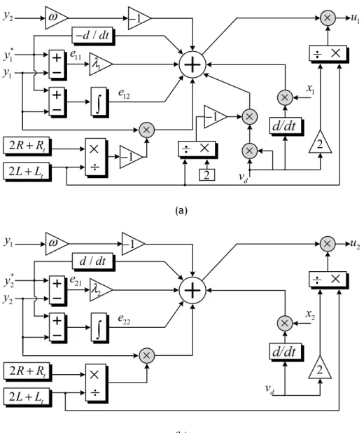
14Figure 2.2 The proposed control technique of DFT (a) the component of (b) the component of
……….
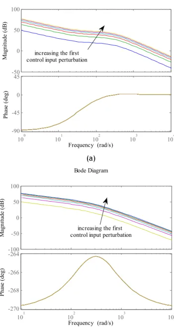
20Figure 2.3 The perturbation effect of first control input on (a) the first flat output (b) the second flat output
………
22Figure 2.4 The effects of second control inputs on (a) the first flat output (b) the second flat output
………
23Figure 2.5 The single diagram of simulated model
……….
24Figure 2.6 SM’s voltages of MMC
……….
25Figure 2.7 Voltage at PCC in phase “a”
………
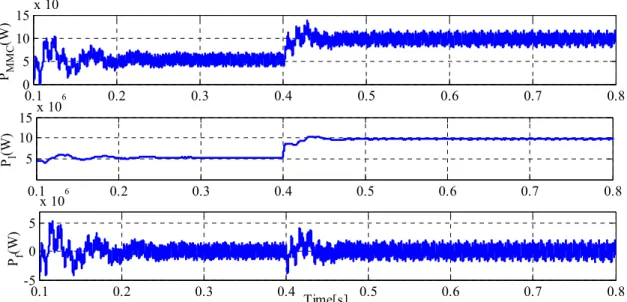
25Figure 2.8 Active power of MMC, load and AC filter
………
… 25Figure 2.9 Reactive power of MMC, load and AC filter
……….
26Figure 2.10 SM’s voltages of MMC with load variations at t=0.4 s
……….………….
27Figure 2.11 PCC voltage of phase “a” with load variations at t=0.4 s
……….
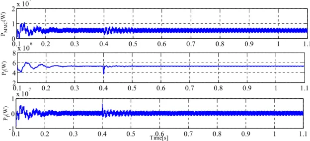
27Figure 2.12 Active power of MMC, load and AC filter with load variations at t=0.4
……
28Figure 2.13 Reactive power of MMC, load and AC filter with load variations at t=0.4s
………
28Figure 2.14 SM’s voltages of MMC with parameters variations at t=0.4 s
………
29Figure 2.15 PCC voltage of phase “a” with parameters variations at t=0.4 s
………
29Figure 2.16 Active power of MMC, load and AC filter with parameters variations at t=0.4 s
……….
30xiii Figure 2.17 Reactive power of MMC, load and AC filter with parameters variations at
t=0.4 s
……….
30Figure 3.1 Schematic diagram of the MMC-HVDC system. (a) Single-line diagram model and (b) circuit diagram of the back-to-back MMC
……….……….
35Figure 3.2 (a) Power curve of MMCs (b) R and L changes effects on MMCs power
curve
……….
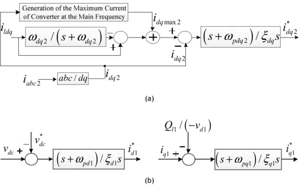
40Figure 3.3 The proposed outer loop controller for (a) MMCs currents (b) MMCs circulating currents
………
44Figure 3.4 The Proposed Central Loop Controller for (a) MMCs currents (b) MMCs circulating currents
………
46Figure 3.5 The Proposed Inner Loop Controller for (a) the MMC2 reference currents (b) the MMC1 reference currents
……….
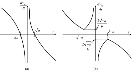
47Figure 3.6 The phase diagrams of the DC-link voltage (a) a>0 and (b) a<0
………
49Figure 3.7 Block diagram of the proposed control technique for the MMC-HVDC system in Figure 3.1
……….……….
51Figure 3.8 The upper and lower switching functions of phase “a’ of (a) MMC1 (b) MMC2, under load changes
……….
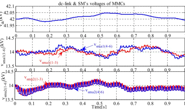
53Figure 3.9 MMCs DC-link and Sub-Module’s voltages with load changes
…….…………
53Figure 3.10 MMCs AC voltages with load changes
………
54Figure 3.11 MMCs Circulating currents with load changes
……….
54Figure 3.12 Active and reactive power of MMCs, load, and AC filter with load
changes
………
55Figure 3.13 Parameters changes for (a) the resistance of MMCs (b) the inductance of
MMCs
……….………
56Figure 3.14 The upper and lower switching functions of phase “a’’ of (a) MMC1 (b) MMC2, under MMC parameters changes
……….
57xiv Figure 3.15 MMCs DC-link and SM’s voltages with parameters changes
………
58Figure 3.16 MMCs AC voltages with the parameters changes
………
58Figure 3.17 MMCs circulating currents with parameters changes
………
59Figure 3.18 Active and reactive power of MMCs, load, and AC filter with parameters
changes
………
59Figure 4.1 (a) The proposed MMC, (b) sub-module
……….
64Figure 4.2 The equivalent capacitor of (a) upper modules (b) lower
sub-modules
………
72Figure 4.3 The overall structure of the proposed controller
……….
73Figure 4.4 In load changes process, a) The proposed three-phase upper and lower modulation functions with its carrier waves, b)the generated switching signals for upper sub-modules in phase “a” c) the generated switching signals for lower sub-modules in phase “a”
……….
75Figure 4.5 (a) The sub-module voltages of phase “a” (b) The output voltages of MMC before and after connecting AC filter capacitor under load change
condition
……….
76Figure 4.6 (a) The output and circulating currents of the MMC. (b) Active and reactive power of the MMC under load changes condition
………
77Figure 4.7 Angle Difference between output MMC voltages and Currents under load changes condition
………
78Figure 4.8 In parameters changes condition, a) The proposed three-phase upper and lower modulation functions with its carrier waves, b)the generated switching signals for upper sub-modules in phase “a” c) the generated switching signals for lower sub-modules in phase “a”
……….
79Figure 4.9 (a) The sub-modules voltages of phase “a” (b) Output voltages of MMC before and after connecting AC filter under parameters change
xv Figure 4.10 (a) Output and circulating currents of the MMC (b) Active and reactive
power of the MMC under parameters changes condition
………
81Figure 4.11 Angle Difference between output MMC voltages and Currents under parameters changes condition
………
82Figure 5.1 (a) The proposed three-phase modular multilevel converter (MMC) based model; and (b) sub-module (SM)
………
85Figure 5.2 The proposed modulation functions for phase “a”
………
89Figure 5.3 The proposed modulation index and function as to parameters given in
Table 5.1
……….………
89Figure 5.4 The proposed modulation index and function based on parameters variations given in Table 2
……….
90Figure 5.5 A typical shifted-level pulse width modulation (PWM) for proposed upper modulation function with parameter changes
………
91Figure 5.6 A typical shifted-level PWM for proposed lower modulation function with parameter changes
……….
91Figure 5.7 The proposed modulation index and function based on input variable
variations
………
92Figure 5.8 A typical shifted-level PWM for proposed upper modulation function with input current changes
………..
92Figure 5.9 A typical shifted-level PWM for proposed lower modulation function with input current changes
………
93Figure 5.10 The overall structure of the proposed modulation functions for MMC
…….
93Figure 5.11 SM voltages of MMC with parameter variations
……….
94Figure 5.12 DC-link voltage of MMC with parameter variations
……….……….
95Figure 5.13 MMC current of phase “a” with parameter variations
……….
95xvi Figure 5.15 Circulating current of MMC in phase “a” with parameter
variations
………
96Figure 5.16 SM voltages of MMC with input MMC current
variation
……….
97Figure 5.17 DC-link voltage of MMC with input MMC current
variations
……….……….
97Figure 5.18 MMC current of phase “a” with MMC input current
variations
………
97Figure 5.19 The active and reactive power of MMC with MMC input current
variations
………
98Figure 5.20 Circulating current of MMC in phase “a” with input MMC current
variations
……….……….
98Figure 6.1 General model of the proposed MMC-based HVDC system
……….
102Figure 6.2 Equivalent circuits of: (a) Dynamic model based on MMC output currents, (b) dynamic model based on circulating currents
……….
103Figure 6.3 Calculation of MMC output currents
………
105Figure 6.4 Switching functions based on MMC output currents (a) d-component, (b)
q-component
……….
105Figure 6.5 Switching functions based on circulating currents (a) d-component, (b) q-component, (c) 0-component
………
106Figure 6.6 Different states of vdc and dvdc/dt
………
109Figure 6.7 Capability curve of MMCs (a) increasing > 0, (b) decreasing
<
0……….
111Figure 6.8 Nyquist diagram of DC-link voltage variations for > 0 due to (a) d-component variations of MMC current ( ) (b) q-d-component variations of MMC current ( ) (c) DC-link current variations
( )……….
113xvii Figure 6.9 Nyquist diagram of DC-link voltage variations for < 0 due to: (a)
d-component variations of MMCs currents ( ), (b) q-d-component variations of MMCs currents ( ), and (c) DC-link current variations
( )………….
114Figure 6.10 Overall structure of the proposed controller
……….
115Figure 6.11 SM voltages and DC and AC side voltages of MMCs without DLM
………
116Figure 6.12 SM voltages and DC and AC side voltages of MMCs with DLM
……….
117Figure 6.13 Circulating, DC-link and AC-side currents of the interfaced MMCs without
DLM
……….……….
118Figure 6.14 Circulating, DC-link and AC-side currents of the interfaced MMCs with
DLM
……….……….
119Figure 6.15 d and q components of MMCs currents without DLM
……….………….
120Figure 6.16 d and q components of MMCs currents with DLM
………
121Figure 6.17 MMC1 and MMC2 active and reactive power waveforms without DLM
…….
122xviii
List of Tables
Table 2.1 The proposed MMC model specifications with related loads
……….
26Table 2.2 The second parameters for the proposed MMC model
……….
29Table 3.1 Simulation Parameters
………
50Table 4.1 The parameters of the proposed MMC in load changes conditions
……….
73Table 4.2 The parameters of the proposed MMC in parameters changes
conditions
………
74Table 5.1 Simulated system parameters. AC: alternating current; DC: direct
current
……….………
90Table 5.2 Changes in MMC parameters in Condition 2
……….
90xix
List of Symbols
The main notations used in Chapters 2, 3, 4, 5 and 6 are listed below. Other symbols are defined where they first appear.
Chapter 2
Sets and Indices i 1,2 j 1,2 k a,b,c Parameters L Output inductance of MMC R Output resistance of MMC Lt Arm’s inductance of MMC Rt Arm’s resistance of MMC Cf AC Filter Capacitor Cdc DC-link Capacitor
N Sub modules numbers in per arm Variables
ik Output Currents of MMC
iuk Upper’s arm Currents of MMC
ilk Lower’s arm Currents of MMC
icirk Circulating Currents of MMC
idq Output Currents of MMC in d-q reference frame
icir0 Circulating Currents of MMC in 0dq reference frame
vdc DC link voltage of MMC
vuk Upper’s SM voltages of MMC
vlk Lower’s SM voltages of MMC
xx udq The control factors of MMC in d-q reference frame
vk PCC voltages
vm The maximum magnitude of PCC voltages
vdq PCC voltages in d-q reference frame
P Instantaneous active power of MMC Q Instantaneous reactive power of MMC y12 Flat Outputs
x123 The state variables
u12 The control inputs
ei1 The proportional errors of the flat outputs
ei2 The integral errors of the flat outputs
i
y
Δ The perturbations of flat outputs
i
u
Δ The perturbations of control inputs
Chapter 3 Indices K a, b, c J 1,2 Parameters ( )
1/
ξ
dq Proportional gainL
Inductance of the MMCsR
Resistance of the MMCs p L Arm’s inductanceCeq Equivalent DC-link capacitor
Rdc Equivalent DC-link resistance
0
dq j
R Injection resistances
xxi
fs Switching frequency
n Numbers of SMs in each arm
C Capacitor of SM Cfi Capacitor of AC filter ( )dq2
,
( )dqmax 2ω
ω
Cut-off frequency ( )2/
( ) p dq dqω
ξ
Integral gain ( )dq jk
Positive constant of CLC ( ) cir dq jψ
Positive constant of CLC ( )dq jψ
Positive constant of CLC Variables * jQ
Reference values of Reactive power of MMCs( )dq j( )
H s Transfer function
dqj
Z
Error vectordqj
E
Total saved energydqj
S
Time-variable sliding surfacec
v
Rated capacitor voltage( )ul jk
S
Switches of the MMCs( )ul kj
v
Lower and upper arms voltageskj
v
Output voltages of the MMCsvdc DC-link voltage
1
kj
u
First equivalent modulation function of therespective SM stacks 2
kj
u
Second equivalent modulation function of thexxii ( ) sm ul kj
v
SMs voltages ( ) t dq jv
AC-side voltages of the MMCs( )*dq j
v
Reference value of output voltages of the MMCs*
dc
v
Reference value of DC-link voltagekj
i
Currents of MMCscirkj
i
Circulating currents of the MMCs( )ul kj
i
Lower and upper arms currentsdcj
i
MMCs DC-link currents ( ) sm ul kji
Currents of SMs ( )*dq ji
Reference values of MMCs currents( )
*
cir dq j
i
Reference values of circulating currents( )
l dq j
i
Load currents( )
av dq j
I
Average currents of the MMCs( )dqmaxj
i
Maximum value of MMCs currents( ) 1 l d q h h i ∞ =
Total harmonic current components of loadsj
P
Injected active power of MMCsj
Q
Injected reactive power of MMCs*
j
xxiii Chapter 4 Indices k a,b,c j 0,-1,1 i u,l Parameters L Output inductance of MMC R Output resistance of MMC Lt Arm’s inductance of MMC Rt Arm’s resistance of MMC Leq Equivalent inductance of MMC Req Equivalent resistance of MMC
ω
Angular frequency of MMCβi(012) Harmonically coefficients of sub-module powers
βxi(012) Harmonically coefficients of arm’s inductance and resistance powers
α Angle Difference between output MMC voltages and Currents ϴi Phase angle of modulation functions
Variables
ik Input MMC Currents
ilk Arm Currents of MMC
icirk Circulating Currents of MMC
dc
i
MMC DC-link Currentvdc MMC DC-link Voltage
vik Sub-modules Voltages of MMC
vk Output voltages of MMC
vix The voltage of arm’s resistance and inductance
xxiv pix The power of arm’s resistance and inductance
p3φ Output Active power of MMC
q3φ Output Reactive power of MMC
Idc DC component of DC-link current
idcrip Ripple parts of DC-link current
dcrip
i
Derivative of DC-link current ripple partsIm Magnitude of output MMC Currents
Vm Maximum Magnitude of output MMC Voltages
Vmi Magnitude of the proposed modulation functions
Chapter 5
Parameters
Lk Input inductance of MMC
Rk Input resistance of MMC
Lkul Arm’s inductance of MMC
Rkul Arm’s resistance of MMC
Lkt Equivalent arm’s inductance of MMC
Rkt Equivalent arm’s resistance of MMC
ω Angular frequency of MMC
Variables
ik Input MMC currents
Imk Magnitude of input MMC currents
iku Upper arm currents
ikl Lower arm currents
* mk
I Reference values of input MMC currents vks Input MMC voltages
xxv vkl AC-side voltages
vm Magnitude of input MMC voltages
* m
v Reference value of input MMC voltage vku Upper arm voltages
vkl Lower arm voltages
vDC MMC DC-link voltage
uku Switching function for Upper’s arms
ukl Switching function for Lower’s arms
mk Proposed modulation index
αk Angle between input MMC voltages and currents
*
αk Reference value of α
Vkt Magnitude of upper and lower voltage difference
θkt Angle of upper and lower voltage difference
Chapter 6 Indices k a,b,c i 1,2 Parameters L MMC inductance R MMC resistance
Lul Upper and lower arm inductance Rul Upper and lower arm resistance Lt Equivalent inductance of MMC arm Rt Equivalent resistance of MMC arm Cdc The equivalent capacitance of MMCs Rdc The total switching loss of MMCs ω Angular frequency of MMC voltage
xxvi
α(1-5)i Coefficients of DLM controller
Variables
iki MMC currents
iulki Upper and Lower arm currents
icirki Circulating currents of MMCs
idci DC link currents of MMCs idqi MMC currents in dq frame
icirdq0i Circulating currents in dq0
* dqi i Reference currents of MMC * 0 cirdq i
i Reference circulating current
* dci
i Reference DC link current Δ idqi MMC currents variations
Δ idci DC link currents variations
Iavdqi Average values of MMC currents
vki Output voltages of MMC
vulki Upper and Lower arm voltages of MMC vdc, DC link voltage
vdqi MMC output voltages in dq frame
* dqi
v Reference MMC output voltages
* dc
v Reference DC link voltage
vtdqi Terminal voltages of MMC
Δvdc DC link voltage variation
Δvdci MMC effects on DC link voltage Pi MMC active power
ΔPi MMC active power variation Qi MMC reactive power
ΔQi MMC reactive power variation
uk(1,2)i MMC switching functions
* 0(12)
dq i
u
Reference MMC switching functionsxxvii
Δudq0(1,2)i Dynamic of MMC switching function
(-ψ, -χ) The center of idi-iqicurve r The radius of idi-iqicurve
(-ψ’, -χ’) The center of Pi-Qicurve r’ The radius of Pi-Qicurve
xxviii
Relevant Acronyms
AC Alternating Current
ASD Adjustable-Speed Drive
AVM Average-Value Model
CB-PWM Carrier-Based Pulse With Modulation
CC Capability Curve
CCSC Circulating Current Suppression Control CHB Cascaded H-bridge Converters
CLC Central Loop Controller CM Common-Mode
CPS-PWM Carrier-Phase-Shift Pulse-Width-Modulation DERs Distributed Energy Resources
DFT Differential Flatness Theory
DLM Direct Lyapunov Method
FACTS Flexible Alternating Current Transmission Systems HVDC High-Voltage, Direct Current
ILC Inner Loop Controller KCL Kirchhoff's Current Law
KVL Kirchhoff's Voltage Law
LPF Low Pass Filter
MIMO Multi-Input Multi-Output MMC Modular Multilevel Converter
MMCC Modular Multilevel Cascade Converter
MPC Model Predictive Control
MSHE Multilevel Selective Harmonic Elimination
MSHE-PWM Multilevel Selective Harmonic Elimination Pulse-Width Modulation NLC Nearest Level Control
NLM Nearest Level Modulation OLC Outer Loop Controller
PCC Point of Common Coupling
PD Phase-Disposition PI Proportional-Integral
PSC Phase-Shifted Carrier
PWM Pulse-Width-Modulation RESs Renewable Energy Resources
xxix SM Sub-Modules
SMC Sliding Mode Control
SMO Sliding Mode Observer
SS Switching Signals
STATCOM Static Synchronous Compensator
SUPWM SM unified PWM
SV Singular Value
THD Total Harmonic Distortion
VSC Voltage-Source Converter
1
Chapter 1
Introduction
1.1 Background
HVDC (high-voltage direct current) is a highly efficient alternative for transmitting the electricity generated through the large scale of renewable energy resources (RESs) included off/on-shore wind farms over long distances and for special purpose applications. For this reason, HVDC transmission systems have been becoming more and more important in an energy landscape that is featured by enhancing the controllers for the used distributed generations. In fact, HVDC systems are able to help three-phase grids get more stabilized and also connected to green power. The future grid can hopefully rely on such systems because of their aforementioned key roles.
Due to the stated issues, HVDC systems have been widely investigated in recent years. To pursue more recent literatures, both control and protection of multi-terminal HVDC systems have been an important research topic that is accomplished in [1]. Optimized algorithms-based methods have also been considered for reaching more stability for HVDC systems [2], [3]. Another important theme related to HVDC systems is the harmonic elimination that has been discussed in [4], [5]. Moreover, unbalanced grid conditions have been realized at solving this challenge for HVDC system [6]. As a good selection for HVDC systems, among the power converters used for HVDC applications, modular multilevel converters (MMCs) have been recently chosen as the main core of HVDC structures because of their characteristics, such as high reliability capability, modular structure, high efficiency, seamlessly DC link, effective redundancy, and excellent output with eliminated harmonic components and minimum passive filter.
Reference [7] has presented several reduced-order small-signal models for MMC in HVDC applications to investigate the criteria including singular values (SVs) of the frequency response, dynamic response in the time domain, and the largest absolute error of SVs. Some MMC energy-based control strategies have been analyzed in [8], VSC-HVDC Links. The expansion of renewable energy resources and their various structures have been involved with MMCs. The subjects pertaining to RERs such as high penetration problems [9], [10], integration of small-scale renewable energy sources into power grid [11], the harmonic current and reactive power compensation [12], microgrid systems [13], etc., will show the importance of an accurate analysis of MMCs for RERs-based applications.
2 For instance, a Static Synchronous Compensator (STATCOM) has been designed for offshore wind farm applications based on a modular multilevel cascade converter (MMCC) in which its asymmetrical reactive power capability has been accurately analyzed as well [14]. Various modulation strategies applied to MMCs have been investigated in [15] for renewable energy integration. The carrier-based pulse with modulation (CB-PWM) techniques, the CB-PWM methods adapted with an additional cell ranking and selection algorithm, the state-of-the-art of zero sequence signals (ZSS) applied on three-phase inverters, the alliance between the ZSS with the CB-PWM, as well as the nearest level modulation (NLM) have been discussed in [15]. As another use of MMCs for RERS [16], the conception of MMCs for high-scale photovoltaic generation based on efficiency criteria has been studied in [17].
1.2 Research Motivation and Problem Definition
The necessity of choosing a suitable converter for high power generation and transmission, especially HVDC systems, has led to proposing a modular converter in [18]. For the full investigation and stable operation of the converter that has been named MMC, many dynamic models have been considered to be proposed [19]. Thus, in the first step, the best mathematical-based description for MMC should be defined from the viewpoint of differential equations.
A phasor format-based model in the rotating d-q coordinate frame has been proposed in [20] for MMC that the modelled for power-flow and parameter studies. The coordinate frame has been shaped at double the fundamental frequency, in steady state. Also, a substantial analytical basis is presented to facilitate direct mathematical manipulations of nonlinear terms in the rotating frame [20].
The reference [21] has designed a continuous model to accurately simulate the blocked state that is very important for accurate simulation of faults. This model is very useful in high-voltage DC applications [21].
Three dynamic linear state-space models of the modular multilevel converter (MMC), which are suitable for small-signal dynamic studies and controller design, have been proposed in [22]. The three models consist of two, six and ten states, respectively. The 2nd- and 6th-order models ignore the dynamics of the second harmonics and circulating current suppression control (CCSC). As the main challenges of dynamic analytical modelling of MMC, the multiplication nonlinear terms are directly converted to the rotating d-q frame.
3 An average-value model (AVM) of the MMCs considering the sub-module capacitor voltage ripple is proposed in [23] to investigate the control dynamic performance of MMCs. In addition, the sub-module capacitors voltage ripple on the MMC dynamic behavior is explored. Also, the equivalent impedances of the DC and AC sides of the MMC are accurately evaluated [23]. Moreover, using the achieved equivalent impedances, a particular AVM of MMCs, consisting of the equivalent capacitors reflecting the capacitor voltage ripple, has been proposed in [23].
Accurate investigation of the aforementioned dynamic models shows that some of them lack circulating current parts with the aim of suppressing this current. also, other dynamic models have not considered step-by-step analysis of all state variables of MMC. Considering both mentioned features is crucial for presenting an appropriate controller for MMC.
Another important issue related to MMC is the nonlinearity features that should be considered for designing any controller for MMC. Many nonlinear control techniques included input-output feedback linearization [24], [25], direct Lyapunov method [26]–[28], sliding mode controller [29], passivity theory-based control technique [30], [31], etc.
A nonlinear robust multi-loop controller has been designed in [32] for two shunt MMC-based voltage source converters and one series capacitor, via control Lyapunov function to reach fast tracking performance, and robustness against system uncertainties and disturbances. By the use of Lyapunov theorem, stability of the closed-loop nonlinear system is proved as well. In addition, the proposed controller has been decentralized using adaptive observer to estimate the nonlocal system parameters [32].
Since MMCs are multi-input multi-output (MIMO) nonlinear systems, a feedback linearization-based current control strategy can be a suitable option for applying to an MMC system, which has been proposed in [33]. In the first step, the nonlinear state function model of the MMC has been driven and then transformed to a linearized and decoupled form with the help of the input-output feedback linearization technique [33]. Based on the linearized system, simple linear controllers are employed to regulate the output and inner differential currents of the MMC.
Reference [34] has proposed a fault detection method based on a sliding mode observer (SMO) and a switching model of a half-bridge for modular multilevel converters which is capable of locating a faulty semiconductor switching device in the circuit. This method can appropriately address the whole stable operations of MMC.
4 A sliding mode control (SMC) based method has been proposed for the MMC in [35]. The analyses accomplished for the system dynamics under the proposed control method, relations among control parameters and their validity conditions can be driven providing a guidance for systematic controller design [35]. The proposed SMC-based method provides comparable steady state performance and fast dynamic responses, without compromising the computational effort or requirement for a precise system model.
As it can be understood from the mentioned literatures with the role of designing nonlinear controllers, considering both load and parameters variations in the duties frame of their proposed control technique were not carefully discussed. Thus, it is necessary to design a comprehensive nonlinear control technique for simultaneously reaching the aforementioned aims in which a complete dynamic model is also used.
1.3 Research Questions, Objectives and Contributions of the
Thesis
This thesis presents two new mathematical models including the flat outputs-based dynamic model with active and reactive power state variables, as well as a comprehensive six-order dynamic model by considering all effects of d-q components of circulating currents. Also, to describe the best performance of MMC, two comprehensive analyses regarding all MMC currents and voltages, as well as the ultimate reference switching functions, are executed in this thesis. In addition, using comprehensive analyses, two novel control strategies have been proposed for MMC so that the controllers have the robustness feature against parameters and load variations. Except for the analysis-based control techniques, several nonlinear control strategies have been designed for MMC in HVDC applications to stabilize the behaviors of all considered state variables. It should be stated that the stable response for MMC is aimed to reach in both steady state and dynamic operating conditions in all accomplished researches.
In particular, the following research questions are addressed:
• How can various parts of the dynamic model of the MMC impact on providing an accurate power sharing of renewable energy resources-based HVDC in the presence of model uncertainties and errors?
• What are the results of using the proposed multi-loop control technique on the stable operation of MMCs in HVDC Transmission Systems, and how will each loop with its duties be appropriately led to stable outputs in various operating conditions?
5 • Which state variables should be more important in a detailed analysis of the MMC structure at reaching flexible modulation functions when the parameter alterations exist in the overall performance of the power system?
• How much considering detailed calculations of MMC PWM modulation functions can ease reaching the desired values for the modulation index and phase, and also what is the effect of the system parameters considered by proposing the modulation index and phase?
• Whether by considering the circulating currents components can cause that the ultimate designed controller shows positive results at controlling MMC in the HVDC system or not?
• What results can be achieved by accurately analyzing the proposed detailed curve based on the active and reactive power generated through MMC and which factors can be used to show other aspects of the proposed curve?
The main objectives of this thesis are as follows:
• To investigate on existing mathematical dynamic models of renewable energy resources-based MMC in various applications and inquire the nonlinearity features of MMC along with their proportional nonlinear control techniques;
• To present a different statement for the dynamic model of MMC based on the defined flat outputs enhanced with robustness ability against both load and parameters variations;
• To develop an appropriate control method by considering sliding mode surface for approaching the state variables errors of MMC to zero for the steady state and dynamic operation of a renewable energy resources-based HVDC transmission while parameters changes are taken into account;
• To present a detailed step-by-step analysis of MMC for achieving the appropriate switching functions that are able to provide the control aims with very high accuracy; • To extract the detailed specifications of various parts of MMC switching functions ignored by existing related works that can enhance the stability of both sides of the HVDC transmission system;
• To develop the existing dynamic models by considering the circulating currents effects in both steady and dynamic states operations;
• To provide a global asymptotical stability for renewable energy resources-based HVDC systems by considering total saved energy of the system in the presence of load changes in both AC sides;
• To present a new algorithm for both MMC currents and power that leads to a new capability curve employed for both steady state and dynamic analysis.
6 The contributions of this thesis (all already published in prestigious venues) are summarized as follows:
• A novel control strategy for MMC is designed based on differential flatness theory (DFT), in which instantaneous active and reactive power values are considered as the flat outputs. Using this model, the flat outputs-based dynamic model of MMC is obtained to reach the initial value of the proposed controller inputs. In order to mitigate the negative effects of input disturbance, model errors and system uncertainties on the operating performance of the MMC, the integral-proportional terms of the flat output errors are added to the initial inputs. This can be achieved through defining a control Lyapunov function which can ensure the stability of the MMC under various operating points. This contribution is published in “IEEE Journal
of Emerging and Selected Topics in Power Electronics” [36];
• A multi-loop control strategy based on a six-order dynamic model of the modular multilevel converter (MMC) is presented for the high-voltage direct current (HVDC) applications. For the initial analysis of the operation of MMC, a capability curve based on active and reactive power of the MMC is achieved through a part of the six order dynamic equations. According to the MMC’s control aims, the first loop known as the outer loop is designed based on passivity control theory to force the MMC state variables to follow their reference values. As the second loop with the use of sliding mode control, the central loop should provide appropriate performance for the MMC under variations of the MMC’s parameters. Another main part of the proposed controller is defined for the third inner loop to accomplish the accurate generation of reference values. By implementing an accurate coordination between the designed control loops, stable responses for all involved state variables are achieved. This contribution has been published in “International Journal of Electrical Power &
Energy Systems” (ELSEVIER) [37].
• A new function-based modulation control technique for modular multilevel converters (MMC) is proposed. The main contributions of the proposed controller are: 1) two separate modulation functions to attain the switching signals of upper and lower sub-modules; 2) the simplicity of the designed controller, especially in comparison with the existing methods; and 3) maintaining stable operation during parameters varying condition due to its structure. Moreover, the effects of the MMC parameters and currents changes are considered as the assessment factors of the proposed modulation functions performance in both steady-state and dynamic conditions. In addition, using the proposed functions, the instantaneous powers of the MMC arms and the equivalent capacitors of the upper and lower sub-modules are evaluated. This contribution is published in “IET Generation, Transmission and Distribution” [38].
7 • A novel modulation function-based method including analyses of the modulation index and phase is proposed for operation of modular multilevel converters (MMCs) in high voltage direct current (HVDC) transmission systems. The proposed modulation function-based control technique is developed based on thorough and precise analyses of all MMC voltages and currents in the a-b-c reference frame in which the alternating current (AC)-side voltage is the first target to be obtained. Using the AC-side voltage, the combination of the MMC upper and lower arm voltages is achieved as the main structure of the proposed modulation function. The main contribution of the proposed work is to obtain two very simple new modulation functions to control MMC performance in different operating conditions. The features of the modulation function-based control technique are as follows: (1) this control technique is very simple and can be easily achieved in a-b-c reference frame without the need of using Park transformation; and (2) in addition, the inherent properties of the MMC model are considered in the proposed control technique. Considering these properties leads to constructing a control technique that is robust against MMC parameters changes and also is a very good tracking method for the components of MMC input currents. These features lead to improving the operation of MMC significantly, which can act as a rectifier in the HVDC structure. This contribution published in “Energies” [39]. • A dynamic model, control and stability analysis of MMC-HVDC transmission systems is
presented. The main contributions are fourfold: (1) obtaining a comprehensive dynamic model in d-q frame for MMC-based HVDC system with six independent dynamical state variables, including two AC currents, three circulating currents, and the DC-link voltage, (2) developing the dynamic parts of switching functions by the use of DLM to reach globally asymptotical stability, (3) deriving a detailed capability curve (CC) based on active and reactive power of the MMC for the proposed system, investigating the impacts of various values of the DC-link currents on CC; it can be used to verify the maximum capacity of interfaced MMC for the injection of active and reactive power into the power grid, (4) performing a comprehensive investigation of MMC output and DC-link current variations effects on DC-link voltage stability by using small-signal analysis. This contribution published in “IEEE Transactions on
8
1.4 Methodology
The mathematical models developed in this thesis are based on the MMC state variables included output voltages, output currents, circulating currents, input voltages, input currents, DC link voltage, active power and reactive power. In order to achieve the main research objectives, beyond the simulation models, this thesis develops the existence of dynamic models by considering circulating currents components and detailed step-by-step analysis of MMC state variables to reach stable responses for the HVDC power system under uncertainty, and a dramatically changing power generation scheme over time.
On the other hand, because of the nonlinearity characteristics of MMC dynamics, the proposed nonlinear control techniques include Flatness theory, direct Lyapunov method, passivity theory-based method, and sliding mode controller, all implemented in MATLAB© SIMULINK environment to considered MMCs in various structures.
1.5 Notation
The present thesis uses the notation commonly used in the scientific literature, harmonizing the common aspects in all sections, wherever possible. However, whenever necessary, in each section, a suitable notation may be used. The mathematical formulas will be identified with reference to the subsection in which they appear and not in a sequential manner throughout the thesis, restarting them whenever a new section or subsection is created. Moreover, figures and tables will be identified with reference to the section in which they are inserted and not in a sequential manner throughout the thesis.
Mathematical formulas are identified by parentheses (x.x.x) and called “Equation (x.x.x)” and references are identified by square brackets [xx]. The acronyms used in this thesis are structured under synthesis of names and technical information coming from both the Portuguese or English languages, as accepted in the technical and scientific community.
1.6 Organization of the Thesis
This thesis encompasses seven chapters that are organized as follows:
Chapter 1 presents a background of the work in the first step. Then, the research motivations and the problem definition are discussed. Subsequently, the next part of this chapter focuses on the research questions and contributions of this thesis. Also, the used methodologies of the thesis are given. In addition, the adopted notations are discussed in the next part. Finally, the chapter concludes by outlining the structure of the thesis.
9 Chapter 2 concentrates on a novel control strategy based on differential flatness theory (DFT) for MMC. Introduction is the first section of this chapter. Then, the second section consists of two sub-sections of dynamic analysis of the proposed MMC-based model as well as the proposed DFT-based control technique. The stability analysis of this chapter is provided by investigating the effects of the control inputs perturbations as the next section. Simulation results and the highlighted points of the chapter are provided afterwards.
Chapter 3 presents a multi-loop control technique for the stable operation of MMCs in HVDC transmission systems. Except for the introduction which is the first section of this chapter, the next section discusses about the proposed differential equation of MMC. This section contains two subsections including the proposed six order dynamic model of MMCs and capability curve analysis of MMCs active and reactive power. Three loops of the proposed control technique are discussed in the control section that encompasses the issues of the design of the outer loop controller (OLC), the design of the central loop controller (CLC) and the design of the inner loop controller (ILC). Convergence evaluation and stability analysis are regarded as the evaluation section of this chapter. The load compensation capability analysis of MMC and dynamic model analysis of the DC-link voltage are discussed in the evaluation section in detail. Finally, simulation results in MATLAB/Simulink environment are presented.
Chapter 4 presents a function-based modulation control for MMCs under varying loading and parameters conditions. Introduction and the proposed modulation functions discussion are the first sections of the chapter. Second section investigates the calculation of the MMC’ arms currents, and the proposed modulation function. Then, the evaluation of the instantaneous power of the MMC arms are executed by calculation of the MMC’ arms currents and instantaneous power of the arm’s resistance and inductance. Next section focuses on the determination of and . Accurate sizing of the equivalent sub-module capacitors is also provided in the next section. Simulation results and highlighted points of this chapter are the last sections, respectively.
Chapter 5 proposes a novel modulation function-based control of MMCs for HVDC transmission systems. Introduction is written in the first section. Then, the detailed calculation of the alternating current-side voltage is accomplished in the next section. The analysis section includes parameters and input current variations effects on the proposed modulation function are accurately discussed. Simulation results are discussed as well.
10 Chapter 6 discusses about dynamic Model, control and stability analysis of MMC in HVDC transmission systems. After introduction, the model of MMC-based HVDC system is proposed. Steady state and dynamic stability analysis are presented in two other sections, respectively. In the next section, capability curve analysis of the MMCs is presented. DC-link voltage stability analysis is placed in the next section. Simulation results and highlighted points of this chapter are given in the next sections.
Chapter 7 presents the main conclusions of this work. Guidelines for future works in this field of research are provided. Moreover, this chapter reports the scientific contributions that resulted from this research work and that have been published in journals, book chapters or in conference proceedings of high standard (IEEE).
11
Chapter 2
Novel Control Strategy for Modular Multilevel
Converters Based on Differential Flatness Theory
This chapter aims to present a novel control strategy for Modular Multilevel Converters (MMC) based on differential flatness theory (DFT), in which instantaneous active and reactive power values are considered as the flat outputs. To this purpose, a mathematical model of the MMC taking into account dynamics of the AC-side current and the DC-side voltage of the converter is derived in a d-q reference frame. Using this model, the flat outputs-based dynamic model of MMC is obtained to reach the initial value of the proposed controller inputs. In order to mitigate the negative effects of the input disturbance, model errors and system uncertainties on the operating performance of the MMC, the integral-proportional terms of the flat output errors are added to the initial inputs. This can be achieved through defining a control Lyapunov function that can ensure the stability of the MMC under various operating points. Moreover, the small-signal linearization method is applied to the proposed flat output-based model to separately evaluate the variation effects of controller inputs on flat outputs. The proficiency of the proposed method is researched via MATLAB simulation. Simulation results highlight the capability of the proposed controller in both steady-state and transient conditions in maintaining MMC currents and voltages, through managing active and reactive power.2.1 Introduction
Considering the issues concerning to the renewable energy resources [41], [42], investigating high-power and Medium-voltage converters has been attracted attention more and more. High-power and Medium-voltage High-power electronics-based converters have been continuously employed in high-technology industries, traction systems and regenerative energy sources, since they offer effective power structures, flexible designed controllers, various dynamic models, and effective pulse-width-modulation (PWM) techniques [43]–[46]. These features can lead to low harmonic components, fast responses against dynamic changes, improved power factors as well as power quality in grid-connected systems, not to mention a ride-through capability and/or a redundant converter design in various operating conditions [47]–[49]. Among existing power electronic-based converters, modular multilevel converters (MMCs) have been gaining popularity due to their full modularity and easy extend ability to meet different voltage and power level requirements in various applications i.e., photovoltaic systems, large wind turbines, AC motor drives, HVDC systems, DC-DC transformers, battery electric vehicles, distributed energy resources (DERs), and flexible alternating current transmission systems (FACTS) [50]–[55].
12 However, the MMCs commonly demand complex control configurations in compression with other converter topologies. Therefore, designing an appropriate control technique for the control and operation of the MMC in power systems is essential. To this end, several studies in the literature have addressed the control concept of the MMCs in power systems which will be briefly presented as follows [56]–[66]. A nearest level control (NLC) along with an optimized control strategy is proposed to govern the MMC operation in [56], which is based on the dynamic redundancy and the utilization ratio of the sub-modules.
A model predictive direct current control is provided for the MMC in [57]. The proposed control technique can maintain the load current within strict bounds around sinusoidal references and minimize capacitor voltage changes and circulating currents. In recent years, dynamic models for MMCs have been the topics of several work [58]–[60]. In [60], a new switching-cycle state-space model is designed for a MMC in which a respective switching-cycle control approach is also proposed by considering the unused switching states of the converter. Through using the average voltage of all the sub-modules (SMs) in each control cycle, a fast voltage-balancing control along with a numerical simulation model are proposed for the MMC in [61]. The sinusoidal common-mode (CM) voltage and circulating currents are employed for designing various control techniques in MMCs. In fact, in order to attenuate the low-frequency components of the SM capacitor voltage, the sinusoidal common-mode voltage and circulating current are used to design a control strategy for the MMC in [62]. In [63], optimized sinusoidal CM voltage and circulating current are used to limit the SM capacitor voltage ripple and the peak value of the arm current. Also, for adjustable-speed drive (ASD) application under constant torque low-speed operation, two control techniques based on injecting a square-wave CM voltage on the AC-side and a circulating current are proposed to reduce the magnitude of the SM capacitor voltage ripple [64]. Furthermore, a control strategy based on a sinusoidal CM voltage and circulating current is proposed for an MMC-based ASD over the complete operating speed region [65]. In addition, the peak value of the sinusoidal common mode voltage can be a key solution for analyzing the SM capacitor voltage ripple [66].
In this chapter, a novel control strategy based on differential flatness theory (DFT), inspired by that was used for the control of converters in [36], [67]–[70], is presented to control the operation of MMC in power systems. The flat outputs required for the DFT based control technique are the instantaneous active and reactive power of the MMC. The initial values of the proposed controller inputs can be driven by a new dynamic equation of the MMC, achieved as per the flat outputs. Then, a control Lyapunov function based on the respective integral-proportional errors of flat output is utilized to provide a stable operation against input disturbance, model errors, and system uncertainties.
13 Also, in order to evaluate the variation effects of controller inputs on flat outputs, the relevant transfer functions are obtained through the small signal model of the flat outputs-based dynamic equations. In comparison with other existing control techniques for MMC, the proposed controller exhibits several considerable advantages in terms of the stability issues for robustness enhancement, highly improvements of MMC power sharing ability, less overshoot and undershoot for SM voltages and transient through considering simultaneously all the input disturbance, model errors, and system uncertainties and applying directly the MMC active and reactive power as the state variables. The simulation analysis using Matlab/Simulink clearly demonstrates the effectiveness of the DFT-based control strategy in the proposed MMC-based model under different operating modes.
2.2 Proposed Control Technique
Figure 2.1 depicts a circuit diagram of the proposed MMC-based model. The MMC consists of six sub-modules in series in each upper and lower arm. Each sub-module can be modeled as a half-bridge IGBT-diode switch-based rectifier. Two resistance-inductance loads are connected to the PCC in which the second load enters in operating mode by means of the switch at a determined time. Also, a capacitor filter is considered at the PCC of the MMC to improve output AC voltages. Since the dynamic equations of the proposed model are considered in the design of the proposed control strategy; thus, these basic equations as well as a new dynamic model based on the outputs of DFT are extracted in this section.
2.2.1 Dynamic Analysis of the Proposed MMC-based Model
As can be seen in Figure 2.1, the series connection of sub-modules in both upper and lower arms of the MMC are represented by the controllable voltage sources of and respectively. These voltages play a key role in controlling the MMC in different operating conditions. As per Figure 2.1, the relationships between arm’s currents and AC voltages of the MMC, taking into account the DC-link voltage and controllable voltage sources, can be expressed as,
0
2
k uk dc k k t t uk ukdi
di
v
v
L
Ri
L
R i
v
dt
dt
+
+
+
+
−
+
=
(2.1)0
2
dc k lk k k t t lk lkv
di
di
v
L
Ri
L
R i
v
dt
dt
+
+
+
+
+
−
=
(2.2)14
2
dcv
2
dcv
dci
i
uc ai
L
R
tL
tR
+
−
uav
av
ubi
i
ua lai
lbi
lci
bv
bi
v
c ci
tL
tR
+
−
lav
PCC
fC
A
B
2
C
dc2
C
dcFigure.2.1. - The circuit diagram of the considered MMC-based model.
By summing (2.1) and (2.2), the basic dynamic model of the proposed MMC-based model can be obtained as, 2 2 0 2 2 t k t k k k L L di R R i u v dt + + + + + = (2.3)
where + = . The control factor of is equal to = ( − )/2 which reflects the effect of both controllable voltage sources. In addition, the DC-link voltage term is eliminated in (2.3). By applying KCL’s law in the determined points of A and B in Figure 2.1, the relationships between the MMC’s arm currents and the DC-link voltage are stated respectively as,