Effect of Bead Overlapping on the Microstructure and Mechanical Properties of CoCrWC
Alloy Coatings
Rodrigo Metz Gabriel Paesa, Douglas Martinazzib , Tiago Falcadeb , Adriano Scheida*
Received: April 17, 2018; Revised: July 09, 2018; Accepted: August 23, 2018
In order to protect industrial components, cobalt base alloys are applied as hardfacing material through welding techniques. A large number of papers have shown that controlling the chemical composition is a key point regarding the wear and corrosion resistance of coatings. This paper investigated the effect of bead overlapping on the microstructure and properties of CoCrWC alloy coatings. Mechanical properties were determined by hardness, sliding wear and microtensile tests. Bead overlapping reduces dilution during the previous bead melting, which in turn induces lower iron content. From the second bead on, an increase in the amount of interdendritic carbides and solid solution alloying was verified, accounting for the higher mechanical properties of the coatings.
Keywords: Cobalt-based Alloy, Coatings, Microstructure, Hardness, Bead Overlapping (BO), Deposition Current.
*e-mail: scheid@ufpr.br.
1. Introduction
Surface engineering continuously seeks to protect industrial components in order to improve their service life, either with new alloys or advanced manufacturing processes. Oil and gas, chemical and petrochemical, nuclear and steelmaking facilities are examples of important industrial usages. Nuclear power plants have reported the risk resulting from the conversion of cobalt wear debris into radioactive
60Co, and have therefore demanded a reduction of wear
rate. Another typical harsh environment is met in hot-dip galvanizing lines. Bushings and bearings are exposed to a complex degradation mechanism, which involves abrasive wear, high temperature and molten metal corrosion, reducing the service life of parts1-6.
In light of this, cobalt base alloys can be applied when these operational requirements are present. Hence, alloys can be selected as wear-resistant bulk or hardface material. Among the options, the carbide reinforced alloy system can be selected for its inherent high strength, wear and corrosion resistance and ability to retain hardness at elevated temperatures7. Its microstructure consists of hard carbide
particles dispersed in a cobalt-rich solid solution matrix (Co-SS)7,8.Therefore, chemical composition considerably
influences microstructure and, of course, mechanical properties and resistance to abrasion, since it dictates the volume fraction of carbides1-3,7,8.
Moreover, the hardfacing of steel substrates has been considered for their attractive properties and relatively low
cost. In fact, dilution should be kept as low as possible, since higher dilution induces a decrease in hardness often associated with microstructure changes, that is, a lower fraction of strengthening carbides and lower alloying in the Co-SS8,11-15. Halstead and Rawlings16 have investigated the
effect of iron additions on Co-based alloys microstructure, and many recent welding papers8,12,14,15 have confirmed a
larger fraction of Co-rich solid solution phase as higher dilution in the steel substrate is achieved8.
Furthermore, since applying welded coatings may optimize the wear resistance of a mechanical component, selecting the appropriate composition of the feeding material is considered the first critical step. Thereafter, substrate and processing parameters arise as decisive factors regarding the microstructure, hardness and wear behavior of coatings8,9.
Despite being widely cited as a potential and attractive process to obtain protective coatings10, plasma transferred
arc requires the adjustment of coating parameters in order to optimize properties. Thus, attempting to understand how to control the interaction with the substrate (dilution) has been addressed most frequently by means of deposition current or heat input11-14.
Finally, many papers have been investigating and modeling the bead-cross section profile and bead overlapping (BO) on the characteristics of a welded surface. Bead width and height, in addition to the area of the cross-section of a single bead and the overlapping degree, have great influence on surface quality and dimensional accuracy17-19, but limited research
on the effect of BO on coatings properties is available15. The aLaboratório de Testes Micromecânicos - LTM, Programa de Pós-Graduação em Engenharia Mecânica,
PGMEC, Departamento de Engenharia Mecânica, Universidade Federal do Paraná, Av. Cel. Francisco H. dos Santos, 210, Curitiba, PR, Brasil
bLaboratório de Metalurgia Física - LAMEF, Programa de Pós-Graduação em Engenharia de Minas,
aim of this study is to assess the effect of bead overlapping on the microstructure and mechanical properties of carbides reinforced Co-based alloy coatings.
2. Materials and Methods
Table 1 shows the chemical composition of the atomized CoCrWC alloy studied. Alloy powder with particle size range between 90 and 150 µm was deposited on a 400 x 400 x 12.5 mm AISI 316L stainless steel plate with no substrate pre-heating or torch oscillation, as seen in Table 2.
Several studies have altered the intensity of the deposition current as a way to investigate the effect of interaction with the substrate (dilution) on single bead coatings8,11-14. Therefore,
it was decided to test the effect of bead overlapping for two current intensities (or two levels of heat input), as shown in Table 3. The first idea behind the experimental approach adopted was to determine the effect of 25 % overlapping on coatings features for the chosen heat inputs (conditions #1 and #2). This overlapping is equivalent to d = 0.75W, where “d” is the distance between the center of two adjacent beads and W is the bead width, according to the methodology proposed by Xiong et al.17. Afterward, the bead overlapping
was increased to 50 % (d = 0.50W 17) for deposits with larger
heat input (Condition #3). It is worth highlighting that the larger width of single bead obtained for the latter induced a productivity equivalent to condition #1, i.e. similar coated width (~40 mm) for a constant bead number.
In a preliminary step to the overlapping tests, a single bead geometry characterization of the coatings processed with 120 and 180 A deposition current (wettability angle, reinforcement thickness and width) was done in accordance with previous papers8,11,13,14.
Fig. 1 schematically shows the coated areas produced, emphasizing the positioning adopted for iron measurements (a), microstructure and hardness evaluation (b). Considering the iron content, the dilution was determined according to the Toyserkani standard methodology cited by Abioye, McCartney and Clare20.
Microstructure was evaluated in the middle of the bead cross-section using Scanning Electron Microscopy (see Fig. 1b). Carbide volume fraction was determined on coatings cross-sections by way of digital analysis of the microstructure using Image J(TM) software21, with sequential stages in order to
obtain binary images. X-ray diffraction analysis using Kα-Cu from 20 to 120º supported the microstructure description.
Micromechanical tensile and abrasive sliding wear tests were used to correlate the deposition current and overlapping with the mechanical properties of the coatings, as can be seen in Fig. 2 and Fig. 3. Pins measuring 4 mm diameter were prepared from coatings by spark erosion cutting technique
Table 1. Chemical composition (wt %) of the materials.
Alloy /
Element Co Cr W C Fe Ni
CoCrWC Bal. 27.9 4.7 1.3 1.8 2.1
Substrate /
Element Fe Cr C Ni PMax. SMax. AISI 316L Bal. 16.78 0.02 10.12 0.04 0.008
Table 2. Processing parameters.
PTA Parameters Conditions
Shielding gas (l/min) 2
Protection gas (l/min) 15
Powder feeding gas (l/min) 2
Deposition rate (Kg/h) 1.3
Travel speed (mm/min) 100
Distance torch / substrate (mm) 10
Electrode diameter (mm) 3.13
Table 3. Evaluating matrix.
# Current (A)Deposition Overlapping (%)Bead Beads Number
Coated Width (mm)
1 120 25
4
38
2 180 25 52
3 180 50 40
Figure 1. Schematic showing coated area: (a) Positioning of Spectrometry Analysis and (b) Microstructure and Hardness Tests.
Figure 2. Schematic positioning of microtensile specimens and
wear pins (a) and detail showing the top of the pins with the hardface coatings (b).
(see Fig. 2). They were weighted before the test, worn out against SiC paper #600 with 5 N load and 1.5 m/s tangential speed and re-weighted after each 125 m sliding distance, in order to determine the mass loss coefficient.
Tensile tests were used to assess the yield and tensile strength for the fourth deposited bead (Fig. 2a). Elongation was also determined using MTS laser strain gauge, model LX500, bonding a reflective tape on the specimens with a known distance of 6 mm gauge length (Lo). Then, the distance between tapes was monitored and recorded in order to calculate elongation (ε = δL/L0 (%)).
3. Results
3.1 Dilution and bead geometry
Table 4 presents the geometry of single bead coatings, including wettability angle, width and reinforcement thickness. Visual inspection revealed sound coatings with no cracks or porosity, as shown in Fig. 4. Fig. 5 shows the iron content
bead by bead and dilution curves of the coatings. It is worth noting that bead overlapping promoted a reduction in the iron content, thus reducing the dilution of coatings.
3.2 Coatings microstructure
Coatings microstructure was comprised of cobalt-rich solid solution dendrites and an interdendritic region containing carbides, as seen in Figs. 6-8. Higher carbide fraction was measured for lower heat input8,10,11,14 and higher
bead overlapping.
Two different carbides were formed on coatings: dark gray color M7C3 type (where M: Chromium) in the interdendritic
eutectic lamellar structure, and dispersed M2C white blocky
(where M: Tungsten), as previously reported by literature and shown in Fig. 98.
Fig. 10 and Table 5 present the results of the additional punctual semi-quantitative Energy Dispersive Spectrometry (EDS), used to better describe the microstructure and the effect of interaction with the substrate on carbides and
Co-Table 4. Single bead geometry.
Substrate Geometry Parameter Deposition Current (A)
120 180
AISI 316L
Wettability Angle, θ (0) 42.0 38.6
Reinforcement
Thickness, t (mm) 3.0 2.7
Width, W (mm) 12.5 16.0
Figure 4. Typical macrography of the coatings.
Figure 5. Measured Iron Content (a) and Dilution bead by bead (b).
Figure 6. Typical coatings microstructure: 120 A, 25 % overlapping.
Figure 7. Typical coatings microstructure: 180 A, 25 % overlapping.
Figure 9. Typical difractograms for multiple bead coatings.
Figure 10. Typical EDS punctual analysis on the carbides.
Table 5. Punctual analysis of Iron Content in cobalt-rich solid solution
Phase NumberBead 120 A - Iron – wt %
25% 180 A - 25% 180 A - 50%
Co-rich
Solid Solution
1 17.6 32.6 33.8
2 15.2 27.0 25.8
3 14.2 26.8 23.2
4 11.1 26.7 23.3
rich solid solution. Punctual analyses were carried out bead by bead on the carbides, and confirmed that the dark gray are Chromium-rich and the white blocky are Tungsten base carbides (see Fig. 10). Further analysis involved punctual evaluation of iron content in Co-rich solid solution (Table 5).
3.3 Mechanical behavior of the coatings
In accordance with previous papers8,11-15, coatings showed
hardness dependence in relation to the deposition current, associated with the heat input on welding. The higher the heat input, the larger the microstructure coarsening (higher DAS - dendrite arm spacing) and dilution, accounting for the lower hardness verified for the 180 A deposition current. Furthermore, bead overlapping induces an increase in hardness from the second bead on, as shown in Fig. 11.
Figure 11. Coatings Hardness.
Linear correlation between sliding distance and mass loss and a near constant wear rate were measured with increasing sliding distance, in agreement with previous results6,8,23.
Mass loss rate was influenced by the differences in the microstructure and hardness due to processing, as shown in Fig. 12 and Fig. 13. Results indicate that either deposition
Figure 12. Mass loss versus distance for 25 % overlapping: (a) 120 A and (b) 180 A.
Figure 13. Mass loss versus distance for 180 A / 50 % overlapping and (b) Mass Loss Coefficient Summary.
current or overlapping have influenced the performance of the coatings.
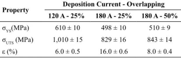
Figure 14. Typical tensile testing curves of the coatings.
Table 6. Summary of the tensile results with standard deviation
Property Deposition Current - Overlapping 120 A - 25% 180 A - 25% 180 A - 50%
σYS(MPa) 610 ± 10 498 ± 10 510 ± 9
σUTS (MPa) 1,010 ± 15 829 ± 16 843 ± 14
ε (%) 6.0 ± 0.5 16.0 ± 0.6 8.0 ± 0.4
4. Discussion
Figure 5 clearly shows the effect of deposition current and bead overlapping on the dilution of coatings, i.e. high values can be observed for the first bead and, of course, for a higher deposition current. In fact, an interesting finding concerning the overlapping-dilution correlation is that as a new bead is applied for a constant heat input, a decrease in dilution is observed. Such drop in dilution is most pronounced in the second and third beads. Paes and Scheid8 evaluated
a CoCrWC alloy by PTA on stainless steel AISI 316 L and reported a drop in dilution as a lower deposition current was adopted for single bead coatings. Similar effect of deposition current on dilution was confirmed in this research.
Apart from the dilution gradient observed in the coatings from the first to the fourth bead and also different dilution levels as a result of deposition current, differences in the chemical composition did not lead to the development of distinct phases in the coatings. A comparative approach of the XRD analysis indicated a cobalt-rich solid solution, M7C3
(M: chromium) and M2C (M: tungsten) carbides (Fig. 9) and
hence, processing parameters have fundamentally influenced phase fraction in the alloy system studied (see Figs. 6-8). An investigation of the chemical distribution by EDS (Fig. 10) also pointed out the main phases in the microstructure and confirmed the results obtained in the chemical composition (spectrometry), showing a similar tendency regarding the iron content punctually analyzed in the Co-SS (Table 5).
In fact, it is believed that for the materials and conditions of testing employed here, the phase fraction in the microstructure is actually governed by a competitive
process, which involved overlapping and deposition current. Considering the two levels of deposition current and bead overlapping evaluated, it is evident that deposition current showed to be the most relevant in relation to coatings dilution and microstructure. In addition, it is also worth highlighting the effect of overlapping when processing coated areas, once significant differences were observed, especially at the beginning of coatings (see Fig. 6-8). Regarding the effect of overlapping, it is reasonable to propose a model for the experimentally verified influence, as shown in Fig. 15.
Fig. 15 clearly shows that the dilution of multi-bead coatings is partially related with the previous bead melting (P) and substrate melted area (S). Hence, both “P” and “S” are directly dependent on the overlapping degree. This is a quite straightforward claim if the iron content is compared bead by bead for 120 and 180 A with 25% overlapping. Still, results become even more interesting if we compare the iron content of the specimens processed with 180 A for overlapping of 25 and 50%.
One of the main objectives of this research was also to correlate the effect of processing with the microstructure and mechanical behavior, and in effect it seems to inevitably not consider the effect of overlapping and deposition current (i. e. iron content) on hardness and wear behavior. Indeed, as the dilution increases, higher iron content tends to decrease the alloying elements such as Chromium, Tungsten and Carbon (see Fig. 9). Therefore, lower deposition current and higher overlapping degree promoted an increase in hardness, associated with higher volume fraction of carbides and solid solution strengthening (see Fig. 11).
Moreover, wear evaluation also confirmed important differences, which can be directly associated with microstructure (seeFigs. 12 and 13). Higher mass loss rate was measured for 180 deposition current, associated with lower carbide fraction. Likewise, better wear performance or lower mass loss rate was verified as a new bead was processed. Carbide fraction was clearly influenced bead by bead, accounting for the differences in performance observed for both 25 and 50 % overlapping. Finally, the best wear performance was obtained for the fourth bead at 120 A (25 %), due to higher quantity of interdendritic eutectic carbides.
Although differences were observed bead by bead, it was decided to evaluate tensile properties in the fourth deposited bead. It is now clear that, despite the larger differences correlated with the deposition current, significant
4. Zhang K, Battiston L. Friction and wear characterization of
some cobalt- and iron-based superalloys in zinc alloys baths. Wear. 2002;252(3-4):332-344. DOI: https://doi.org/10.1016/
S0043-1648(01)00889-4
5. Zhang K. Effects of test conditions on the tribological behavior
of a journal bearing in molten zinc. Wear. 2005;259(7-12):1248-1253. DOI: https://doi.org/10.1016/j.wear.2005.01.003
6. Scheid A, D'Oliveira ASCM. Effect of temperature and reactivity of molten 55Al-Zn alloy on Co based alloy coatings.
Materials Science and Technology. 2010;26(12):1487-1493. DOI: http://dx.doi.org/10.1179/174328409X428954
7. Çelik H, Kaplan M. Effects of silicon on the wear behaviour
of cobalt-based alloys at elevated temperature. Wear.
2004;257(5-6):606-611. DOI: https://doi.org/10.1016/j.
wear.2004.03.008
8. Paes RMG, Scheid A. Effect of deposition current on microstructure and properties of CoCrWC alloy PTA coatings.
Soldagem & Inspeção. 2014;19(3):247-254. DOI: http:// dx.doi.org/10.1590/0104-9224/SI1903.07
9. Venkatesh B, Sriker K, Prabhakar VSV. Wear Characteristics
of Hardfacing Alloys: State-of-the-art. Procedia Materials Science. 2015;10:527-532. DOI:10.1016/j.mspro.2015.06.002
10. Gonçalves e Silva RH, Dutra JC. PTA-P process - a literature
review as basis for innovations. Part 1 of 2: constructive elements. Soldagem & Inspeção. 2012;17(1):76-85. DOI: 10.1590/S0104-92242012000100011
11. Antoszczyszyn TJ, Paes RMG, de Oliveira ASCM, Scheid
A. Impact of dilution on the microstructure and properties of Ni-based 625 alloy coatings. Soldagem & Inspeção.
2014;19(2):134-144. DOI:
http://dx.doi.org/10.1590/0104-9224/SI1902.05
12. Yaedu AE, D'Oliveira ASCM. Cobalt based alloy PTA hardfacing on different substrate steels. Materials Science and Technology. 2005;21(4):459-466. DOI: https://doi.org /10.1179/174328413X13789824293380
13. Ferreira LS, Graf K, Scheid A. Microstructure and Properties of Nickel-based C276 Alloy Coatings by PTA on AISI 316L
and API 5L X70 Steel Substrates. Materials Research.
2015;18(1):212-221. DOI:
http://dx.doi.org/10.1590/1516-1439.332914
14. Bohatch RG, Athayde JN, Siqueira JCM, D´Oliveira ASCM, Scheid A. Influence of Processing on the Microstructure and Properties of CoCrMoSi Alloy PTA Coatings. Soldagem & Inspeção. 2015;20(2):219-227. DOI: 10.1590/0104-9224/ SI2002.09
15. Bohatch RG, Graf K, Scheid A. Effect of Track Overlap on the Microstructure and Properties of the CoCrMoSi PTA Coatings. Materials Research. 2015;18(3):553-562. DOI: http://dx.doi.org/10.1590/1516-1439.340014
16. Halstead A, Rawlings RD. The effect of iron additions on the microstructure and properties of the "Tribaloy" Co-Mo-Cr-Si wear resistant alloys. Journal of Materials Science.
1985;20(5):1693-1704. DOI: https://doi.org/10.1007/
BF00555273 differences due to the overlapping degree were observed in
the mechanical behavior (see Fig. 14 and Table 6). On the one hand, dilution increase led to lower yield and ultimate tensile strengths, in contrast with the positive effect on ductility of coatings (higher elongation). Tensile properties were altered basically due to different carbide fraction and solid solution strengthening. Evidently, the first altered the free lengths of dislocation lines, modifying the shear stresses required for moving the dislocation line segments, and the latter (solid solution alloying) affected the dislocation mobility 24.
5. Conclusions
The effect of bead overlapping on the microstructure and properties of CoCrWC alloy coatings processed on AISI 316L steel were assessed. The following conclusions can be presented:
• Regarding the same heat input on welding, dilution directly depends on bead overlapping and bead number, although greater differences were verified for beads 1 to 3.
• Properties of carbide reinforced alloys processed by way of coated areas must take into account deposition current and bead overlapping, despite the first parameter being the most influential. • Hardness and wear evaluation indicated that the
overlapping effect was more pronounced in the second and third beads. The greater the overlapping, the higher the hardness and wear resistance of coatings. • Lower dilution induced higher yield and ultimate
tensile properties and lower elongation for CoCrWC alloy coatings, basically due to the effect of iron content on solid solution alloying and carbide fraction.
6. Acknowledgements
The authors would like to thank LAMEF - Physical Metallurgy Laboratory for the characterization support.
7. References
1. Chen J, Li XY, Bell T, Dong H. Improving the wear properties
of Stellite 21 alloy by plasma surface alloying with carbon and nitrogen. Wear. 2008;264(3-4):157-165. DOI: 10.1016/j. wear.2006.12.012
2. Lemaire E, Le Calvar M. Evidence of tribocorrosion wear in
pressurized water reactors. Wear. 2003;249(5-6):338-344. DOI:
10.1016/S0043-1648(00)00544-5
3. Scheid A, Schreiner WH, D'Oliveira ASCM. Effect of temperature on the reactivity between a CoCrMoSi alloy and 55 wt% AlZn
17. Xiong J, Zhang G, Gao H, Wu L. Modeling of bead section profile and overlapping beads with experimental validation for robotic GMAW-based rapid manufacturing. Robotics and Computer-Integrated Manufacturing. 2013;29(2):417-423. DOI: http://dx.doi.org/10.1016/j.rcim.2012.09.011
18. Cao Y, Zhu S, Liang X, Wang W. Overlapping model of beads and curve fitting of bead section for rapid manufacturing by robotic MAG welding process. Robotics and Computer-Integrated Manufacturing. 2011;27(3):641-645. DOI: 10.1016/j.rcim.2010.11.002
19. Suryakumar S, Karunakaran KP, Bernard A, Chandrasekhar U, Raghavender N, Sharma D. Weld bead modeling and process optimization in Hybrid Layered Manufacturing.
Computer-Aided Design. 2011;43(4):331-344. DOI: 10.1016/j. cad.2011.01.006
20. Abioye TE, McCartney DG, Clare AT. Laser cladding of Inconel
625 wire for corrosion protection. Journal of Materials Processing Technology. 2015;217:232-240. DOI: http://dx.doi.org/10.1016/j. jmatprotec.2014.10.024
21. Rasband WS. Image J. Bethesda: U. S. National Institutes of Health; 1997-2015. Available from: <http://imagej.nih.gov/ij/>. Access in: 20/03/2018.
22. Çam G, Erim S, Yeni Ç, Koçak M. Determination of Mechanical and Fracture Properties of Laser Beam Welded Steel Joints. Welding Research Supplement. 1999;193s-201s.
23. Scheid A, de Oliveira ASCM. Analysis of PTA hardfacing with CoCrWC and CoCrMoSi alloys. Soldagem & Inspeção. 2013;18(4):322-328. DOI: http://dx.doi.org/10.1590/S0104-92242013000400004