1 10º CONGRESSO NACIONAL DE SISMOLOGIA E ENGENHARIA SÍSMICA
Assessment of the in-plane nonlinear behaviour of masonry-infilled RC
frames using micro-modelling approaches
Mohamed, H PhD student Faculty of Engineering, University of Porto, Porto, Portugal. Romão, X. Assistant Professor Faculty of Engineering, University of Porto, Porto, Portugal.
ABSTRACT
Experimental tests are considered the most realistic approach to assessing the nonlinear behaviour of masonry-infilled reinforced concrete (RC) frames. Therefore, their results can be used to validate the properties of macro-models such as strut-type models, which are widely used in performance studies of masonry infilled RC frames due to their computational efficiency. However, the significant cost of experimental tests is the main barrier to their use. This paper introduces the use of detailed finite element models as an alternative to experimental tests to model the behaviour of infilled RC frames. The proposed modelling approach was developed using commercial software (ANSYS®) in order to be more easily replicated by other researchers. The
comparison between numerical and experimental results shows the developed numerical models can capture the nonlinear behaviour of the physical specimens and predict their overall strength and failure mechanisms. Therefore, they can be used as an alternative to experimental tests.
Keywords: Infill walls, Reinforced concrete frame, Finite-element, Contact element, ANSYS
Assessment of the in-plane nonlinear behaviour of masonry-infilled RC frames using micro-modelling approaches
2
1. INTRODUCTION
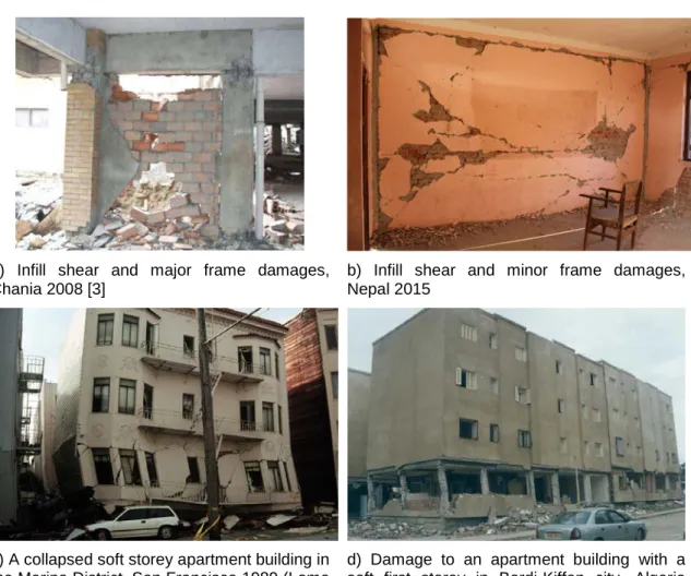
Reinforced concrete (RC) infilled frames are one of most commonly used structural systems in the world, even in earthquake-prone regions. In most designed buildings, the function of the masonry infill does not exceed its architectural function i.e. it is not considered as a structural element. However, past earthquakes (e.g. Turkey, 1999, Chania, 2008 and Nepal 2015) have shown that infill walls interact with the RC structural elements during the earthquake and develop unforeseen failure mechanism as shown in
Figure 1. Therefore, it is important to assess the global structural response of these structures taking into account the effect of the infill walls. Extensive research has been carried out over the years to study the interaction between RC frames and their infill walls. Polyakov [1] conducted the earliest experimental studies which tried to clarify the interaction between these two elements. His study showed that the infill works as diagonal bracing of the RC frame. Accordingly, Holmes [2] replaced the infill panel by a diagonal strut with the same material and thickness of the infill panel. Since then, several attempts were carried out to evaluate the structural properties of the equivalent diagonal strut, which provides a more computationally efficient, though simplified, representation for the behaviour of this type of structures.
a) Infill shear and major frame damages, Chania 2008 [3]
b) Infill shear and minor frame damages, Nepal 2015
c) A collapsed soft storey apartment building in the Marina District, San Francisco 1989 (Loma Prieta Earthquake) [4]
d) Damage to an apartment building with a soft first storey in Bordj-Kiffan city, Algeria 2003 [5]
Figure 1 Damages to masonry infilled RC frames after the several earthquakes
The nonlinear finite element method has been used by many researchers to represent the behaviour of RC infilled frames as an alternative to experimental tests. Stavridis
Assessment of the in-plane nonlinear behaviour of masonry-infilled RC frames using micro-modelling approaches
3 and Shing [6], Mohyeddin et al. [7] and Sattar and Liel [8] are examples of such studies. All of these studies were conducted with different modelling approaches and assumptions according to the potentialities of the selected software packages. ANSYS software has been used by several researchers for the finite element modelling of RC infilled structures and a good match has been obtained between numerical and experimental results representing the behaviour of these structures under monotonic loading [7, 9]. A similar approach is used in the proposed paper in order to develop a detailed FE model for fully and partially infilled RC frames subjected to cyclic loading using ANSYS, thus using this approach as a proxy to the experimental tests. After presenting the characteristics and features of the proposed modelling approach, the results of several experimental tests are used to validate the proposed approach.
2. NUMERICAL MODELLING STRATEGY
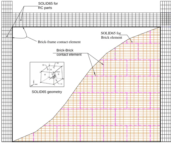
The modelling strategy that was selected involves discretizing the RC-infill structure into individual elements. The ANSYS SOLID65 element was used to represent the brittle components (i.e. concrete and masonry) due to its capability to crack in tension and crush in compression. The longitudinal and transverse steel reinforcement of RC elements was modelled using a smeared approach by using the ability of the SOLID65 element to include reinforcement rebar data in its properties. Finally, in order to model the interaction either between adjacent brick units with themselves or between the brick units and the surrounding RC frame, contact elements were defined between the bricks and between the bricks units the RC frame as shown in Figure 2. According to the type of element, several materials models were used to represent the structural behaviour of each component as described in the following.
Brick-frame contact element Brick-Brick contact element SOLID65 for Brick element SOLID65 for RC parts SOLID65 geometry
Assessment of the in-plane nonlinear behaviour of masonry-infilled RC frames using micro-modelling approaches
4
2.1. Material modelling of reinforced concrete elements
The ANSYS concrete material “CONCR” was used in order to activate the cracking and crushing capabilities of the SOLID65 element. The CONCR material requires the definition of four main parameters. These parameters are the
β
t andβ
c shear coefficients for opened and closed cracks, respectively, the concrete tensile strengtht
f
and the concrete compressive strengthf
c. The value of the tensile strengthf
t, and of the compressive strengthf
c were defined according to experimental data. The parametersβ
t andβ
c control the amount of shear that is transferred across an opened and closed crack, respectively, and their values range from 0 to 1 [10], where 0 represents a smooth crack (i.e. with total loss of shear transfer) and 1 represents a rough crack (i.e. with no loss of shear transfer). The concrete material model CONCR follows the failure surface proposed by William and Warnke [10] where material behaves linearly until crushing or cracking. The cracking follows the stress-stain relation in tension shown in Figure 3, whereT
c is a multiplier accounting for the tensile stress relaxation, E is the initial modulus of elasticity of the concrete, and Rt is the secant modulus of the concrete.Since CONCR material model behaves as a linear elastic material, it is unable to represent the nonlinearity involved in the real behaviour of concrete. For this reason, the constitutive model proposed by Kent and Park [11], known as the “Kent Park model” was used to define a multi-kinematic material model MKIN representing the envelope curve of the hysteretic behaviour for unconfined concrete in compression. For confined concrete, the Kent Park model was replaced by its modified version proposed in [12]. In order to use the multi-kinematic model MKIN to represent the behaviour of concrete in compression, the crushing capability of the SOLID65 element was deactivated to avoid the premature failure of concrete [13], thus guaranteeing that the concrete elements follow the selected constitutive model. The Poisson ratio of the concrete material was considered equal to 0.20.
f t T c ft cr cr 1 E Rt 1 Cracking stress
Figure 3 Stress strain curve of the concrete material model CONCR in tension [14]
The structural behaviour of the steel rebars embedded in the SOLID65 element was modelled using a bilinear stress-strain relation with kinematic hardening. The bilinear material requires the value of the steel yield stress σy, of the initial modulus of elasticity
Es and of the post-yield tangent modulus ET to be fully defined. Under cyclic loading,
the steel material model used considers the Bauschinger effect [15] for the case of the cyclic loading. The tangent modulus ET was assumed to be equal to 2.5% of the initial
modulus of elasticity Es [16]. The Poisson ratio of the steel material was considered
Assessment of the in-plane nonlinear behaviour of masonry-infilled RC frames using micro-modelling approaches
5
2.2. Material modelling of the masonry
The concepts been used to model the concrete material were also used to model the masonry infills material. Therefore, the description provided for the concrete material modelling in terms of tensile behaviour and failure surface is also valid to the modelling of the masonry units. The nonlinear stress–strain curve proposed by Hendry [17] was adopted to model the compression stress state of the brick material:
2 ' 2 m m m m crm crm f ε ε σ ε ε = − (1)
where εm and σm are the compressive strain and the corresponding compressive stress of the masonry,
f
m' is the maximum compressive strength of the masonry andcrm
ε is the maximum compressive strain before failure starts. The Poisson ratio of the masonry material was considered equal to 0.19.
2.3. Modelling of the interface elements
The ANSYS surface contact element pairs CONCTA174 and TARGE170 shown in Figure 4 were used to represent the interaction either between the masonry units or between the masonry infill and the RC frame. The cohesive zone material model (CZM) was used to define the behaviour of the contact elements [14]. The contact pair behaves according to the assigned CZM model. A bilinear model with mixed traction (mode I and mode II) was adopted to account for the possibility of loss of contact in both tension and shear, as shown in Figure 5 a) and b), respectively. This model is based on the model proposed by Alfano and Crisfield [18]. The bilinear relation between the traction stress and its corresponding traction distance δ can be defined by the maximum stress and the maximum traction distance or, alternatively, by the maximum traction stress and the corresponding fracture energy. The input parameters, which are used to define the CZM for the proposed model, are the following: the maximum normal contact stress σmax, the contact gap at full debonding
δ
nc, themaximum equivalent tangential contact stress
τ
max and the tangential slip at fulldebonding
δ
tc.Assessment of the in-plane nonlinear behaviour of masonry-infilled RC frames using micro-modelling approaches
6 max n slope =kn A dn=0 B slope =kn(1-dn) dn=1 C n c n Normal stress (P) max s slope =ks A ds=0 B ds=1 s c s Shear stress ( ) slope =ks(1-ds) in case of cohesion stress (c) interface element Uniform normal displacement
Brick
Brick
interface element Uniform horizontal displacement
Brick
Brick
C
(a) (b)
Figure 5. Bilinear behaviour of the CZM material: a) bilinear definition of cohesive zone model for tensile debonding (mode I); b) bilinear definition of cohesive zone model for
shear debonding (mode II).
3. EXPERIMENTAL DATA OF THE SELECTED CASE STUDIES
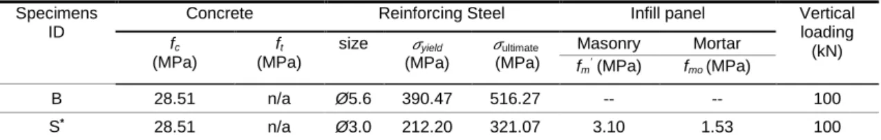
Kakaletsis and Karayannis [19] tested a set of specimens with a 1:3 scale made of single-storey and single-bay frames subjected to reversed cyclic quasi-static horizontal loading up to a drift of 4%. Four specimens from Kakaletsis and Karayannis [19] tests were used to validate the proposed numerical modelling approach. These specimens are the bare RC frame B (Figure 6), the fully infilled RC frame S, the partially infilled RC frame with a centred window opening WO2 and the partially infilled RC frame with a centred door opening DO2. The RC frames of the infilled specimens have the same details of specimen B. Specimen B is used to validate the modelling procedure for the RC elements and the remaining specimens are used to validate the proposed modelling approach for three different configurations of the infill panel. Finally, Table 1 gives the mechanical properties of the selected case studies.
Table 1 - Mechanical properties of the selected case studies and their corresponding numerical terms
Specimens ID
Concrete Reinforcing Steel Infill panel Vertical loading (kN) fc (MPa) ft (MPa) size 𝜎𝜎yield (MPa) 𝜎𝜎ultimate (MPa) Masonry Mortar fm’ (MPa) fmo (MPa) B 28.51 n/a Ø5.6 390.47 516.27 -- -- 100 S* 28.51 n/a Ø3.0 212.20 321.07 3.10 1.53 100
-The tensile strength of concrete ft is computed based on ft=0.623 fc and a similar relation was used between
the compressive and tensile strengths of the masonry. - 𝜎𝜎yield is the steel yield stress
-𝜎𝜎ultimate is the ultimate steel strength
-Based on the 𝜎𝜎yield and 𝜎𝜎ultimate, the tangent modulus ET is defined as 5000 MPa which is 2.38% of the initial Young’s modulus E (200GPa)
- The dimensions of the brick units used in the specimens is 60*60*93 mm3
-The mortar tensile strength was used to represent the normal contact strength σmax between the brick units. * The rest of the specimens (i.e. the partially infilled specimens) have the mechanical properties of specimen S
Assessment of the in-plane nonlinear behaviour of masonry-infilled RC frames using micro-modelling approaches
7 50 0 150 60 800 20 0 100 420 150 1200 150 420 15 0 C C B B A 60 70 100 100 100 70 9Ø3@40 7Ø3@66 9Ø3@40 Ø 3@ 34 Ø3@60 4Ø[email protected] Ø3@60 20 0 100 Sec. B-B 20 0 100 Sec. C-C 3Ø5.6 2Ø5.6 2Ø5.6 2Ø5.6 2Ø5.6 3Ø5.6 Ø3 Ø3 Beam 15 0 150 Sec. A-A 3Ø5.6 2Ø5.6 3Ø5.6 Ø3 Column
Figure 6 Description of specimen B and its reinforcement arrangement [19, 20] (All dimensions are in millimetre).
4. RESULTS OF THE CASE STUDIES AND DISCUSSION
The referred specimens were analysed using the presented modelling approach and using the experimental reversed cyclic quasi-static horizontal loading data as input. All the specimens were analysed for the gravity loading prior to the analyses involving the cyclic loading. In order to assess the ability of the numerical model to capture the failure mechanisms exhibited by the RC frame, Figure 7 compares the crack patterns of specimen B obtained from the numerical model with those from the experimental test. As can be seen, the crack patterns of the numerical model exhibit a reasonable match with the crack propagation pattern found in the columns and beam of the bare frame specimen B.
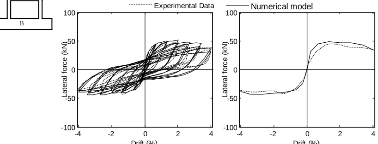
Considering the adequacy of the numerical modelling approach for the RC elements, additional models were then defined for the infilled frames. Given the significant amount of numerical results that were obtained, only a concise presentation of those results in terms of global load-deflection curves is presented herein. The numerical results that were obtained for specimens B, S, WO2, and DO2 are plotted in Figures 8, 9, 10, and 11, respectively. Each figure shows the numerical load-deflection response (where deflection is defined by the lateral drift in %) that was obtained along with the corresponding experimental response. To achieve a better visual comparison, the numerical and experimental hysteretic responses as well as their corresponding envelope curves, are presented for each specimen.
Based on the results obtained for the bare frame specimen that are showed in Figures 7 and 8 the proposed modelling approach for RC frame can be seen to capture the structural behaviour of specimen B adequately, both in terms of failure mechanisms , strength and stiffness. Even though there is an overall good match between the experimental and the numerical cyclic responses, the numerical unloading branches deviate slightly from the experimental results when the drift exceeds 2.5%. This is due to the type of unloading stiffness associated to the material employed in ANSYS to represent the compressive behaviour of concrete, which has an unloading stiffness equal to the initial stiffness, i.e. with no degradation effects. In addition to this effect, the
Assessment of the in-plane nonlinear behaviour of masonry-infilled RC frames using micro-modelling approaches
8 differences between the numerical and the experimental responses can also be the result of other factors such as the existing uncertainty regarding some of the properties of the materials used in the experimental tests. Furthermore, experimental features that are unable to be represented numerically such as the loading rate may also have some influence.
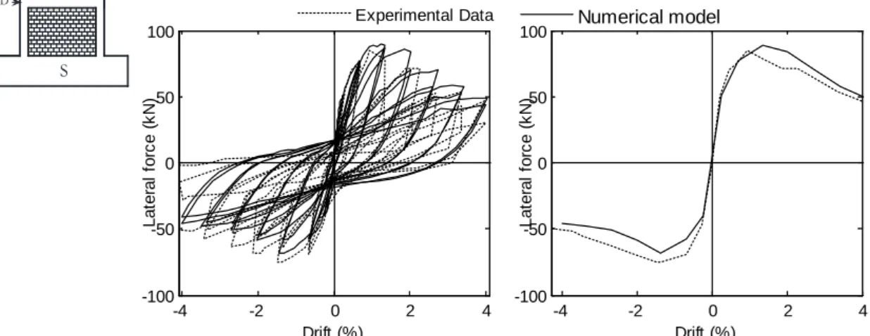
The results obtained for the infilled specimens (i.e. specimens S, WO2 and DO2) are shown in Figures 9 to 11, respectively. From the plots presented, it can be seen that the numerical models are also able to capture the experimental structural response of the infilled specimens with acceptable deviations. Furthermore, the numerical models of the partially infilled specimens (i.e. specimens WO2 and DO2) can be seen to be able capture the strength reduction resulting from the window and door openings.
a) Experimental data b) Numerical model
Figure 7 Crack patterns for the specimen B: a) experimental data; b) numerical model.
B -4 -2 0 2 4 -100 -50 0 50 100 Drift (%) Lat er al f or c e ( k N ) Experimental Data -4 -2 0 2 4 -100 -50 0 50 100 Drift (%) Lat er al f or c e ( k N ) Numerical model
Figure 8. Load–deflection curves obtained from the experimental test and from the numerical model for specimen B.
Assessment of the in-plane nonlinear behaviour of masonry-infilled RC frames using micro-modelling approaches
9 D S -4 -2 0 2 4 -100 -50 0 50 100 Drift (%) Lat er al f or c e ( k N ) Experimental Data -4 -2 0 2 4 -100 -50 0 50 100 Drift (%) Lat er al f or c e ( k N ) Numerical model
Figure 9. Load–deflection curves obtained from the experimental test and from the numerical model for specimen S.
WO2 D -4 -2 0 2 4 -100 -50 0 50 100 Drift (%) Lat er al f or c e ( k N ) Experimental Data -4 -2 0 2 4 -100 -50 0 50 100 Drift (%) Lat er al f or c e ( k N ) Numerical model
Figure 10. Load–deflection curves obtained from the experimental test and from the numerical model for specimen WO2.
D DO2 -4 -2 0 2 4 -100 -50 0 50 100 Drift (%) Lat er al f or c e ( k N ) Experimental Data -4 -2 0 2 4 -100 -50 0 50 100 Drift (%) Lat er al f or c e ( k N ) Numerical model
Figure 11. Load–deflection curves obtained from the experimental test and from the numerical model for specimen DO2.
Assessment of the in-plane nonlinear behaviour of masonry-infilled RC frames using micro-modelling approaches
10
5. CONCLUSION
The proposed paper introduces the use of a detailed finite element modelling strategy to represent the cyclic behaviour of infilled RC frames as an alternative to experimental tests. The proposed modelling approach was developed using commercial software (ANSYS®) in order to be more easily replicated by other researchers.
The presented case study examples show that the proposed micro-modelling approach is able to adequately represent the structural behaviour of masonry infilled RC frame specimens using only the basic mechanical material properties of the structural components. This conclusion is reached based on the ability of the models to capture the failure modes that occurred during the experimental tests, as well as to represent the evolution of the strength and stiffness with a reasonable match with the experimental results. Therefore, the proposed modelling approach can be used as an alternative to experimental tests to evaluate the behaviour of the RC infilled frames in order to get reliable data to calibrate the parameters of simplified strut models that are often used in more simulation-intensive numerical studies (e.g. when analysing the probabilistic behaviour of RC infilled frames under earthquake loading).
6. REFERENCES
[1] S. V. Polyakov, "Masonry in Framed Buildings : An Investigation into the Strength and Stiffness of Masonry Infilling. "Gosudarstvennoe izdatel’stvo Literatury po stroitel’stvu i arkhitekture", Moscow Russia," (English translation by G. L. Cairns, National Lending Library for Science and Technology, Boston, Yorkshire, England, 1963).1956.
[2] M. Holmes. (1961, Steel frames with brickwork and concrete infilling. ICE
Proceedings 19(4), 473-478. Available:
http://www.icevirtuallibrary.com/content/article/10.1680/iicep.1961.11305
[3] B. Li, Z. Wang, K. M. Mosalam, and H. Xie, "Wenchuan Earthquake Field Reconnaissance on Reinforced Concrete Framed Buildings With and Without Masonry Infill Walls," The 14th World Conference on Earthquake Engineering
October 12-17, 2008, Beijing, China, 2008.
[4] P. I. Yanev and A. C. T. Thompson, "Peace of mind in earthquake country," ed, 2008.
[5] N. O. a. A. Administration. (2003). Damage to an apartment building with a soft
first story in Bordj-El-Kiffan city, Algeria. Available:
http://www.ngdc.noaa.gov/hazardimages/picture/show/1108 (accessed
December 2015)
[6] A. Stavridis and P. Shing, "Finite-element modeling of nonlinear behavior of masonry-infilled RC frames," Journal of structural engineering, vol. 136, pp. 285-296, 2010.
[7] A. Mohyeddin, H. M. Goldsworthy, and E. F. Gad, "FE modelling of RC frames with masonry infill panels under in-plane and out-of-plane loading," Engineering
Structures, vol. 51, pp. 73-87, 2013.
[8] S. Sattar and A. B. Liel, "Seismic Performance of Nonductile Reinforced Concrete Frames with Masonry Infill Walls: I. Development of a Strut Model Enhanced by Finite Element Models," Earthquake Spectra, 2015.
[9] A. Mohyeddin, H. M. Goldsworthy, and E. F. Gad, "Sensitivity Analysis of Nonlinear Behaviour of Infill-Frames Under In-Plane and Out-of-Plane Loading,"
Advances in Structural Engineering, vol. 16, pp. 1729-1748, 2013.
[10] K. J. William and E. D. Warnke, "Constitutive model for the triaxial behavior of concrete," in: Proc. of the Int. Association for Bridge and Structural Engineering,
ISMES,, vol. 19, p. 174, 1975.
[11] D. C. Kent and R. Park, "Flexural members with confined concrete," Journal of
Assessment of the in-plane nonlinear behaviour of masonry-infilled RC frames using micro-modelling approaches
11 [12] B. Scott, R. Park, and M. Priestley. (1982, Stress-strain behavior of concrete
confined by overlapping hoops at low and high strain rates. ACI Journal
Proceedings 79(1).
[13] K. Chansawat, D. I. Kachlakev, T. H. Miller, and S. C. Yim, "FE Modeling and Experimental Verification of an FRP Strengthened Bridge," in Proceedings of
the annual conference on experimental and applied mechanics, Portland,
Oregon, USA, 2001, pp. 624-627.
[14] ANSYS "ANSYS theory reference for the mechanical APDL and mechanical applications," in Release 12.1, A. I. Company, Ed., ed. Canonsburg, , Pennsylvania, USA: ANSYS, Inc, 2009.
[15] J. Bauschinger, "Ueber die Veränderung der Elastizitätsgrenze und elastizitätsmodul verschiedener," Metal Civiling N.F., vol. 27 pp. 289-348, 1981. [16] A. Mohyeddin, H. M. Goldsworthy, E. F. Gad, and "FE modelling of RC frames
with masonry infill panels under in-plane and out-of-plane loading," Engineering
Structures, vol. 51, pp. 73-87, 26 February 2013.
[17] A. Hendry, Structural masonry. London, UK: MacMillan Education, Ltd., 1990. [18] G. Alfano and M. Crisfield, "Finite element interface models for the delamination
analysis of laminated composites: mechanical and computational issues,"
International journal for numerical methods in engineering, vol. 50, pp.
1701-1736, 2001.
[19] D. J. Kakaletsis and C. G. Karayannis, "Experimental investigation of infilled reinforced concrete frames with openings," ACI Structural Journal, vol. 106, 2009.
[20] D. J. Kakaletsis and C. G. Karayannis, "Influence of Masonry Strength and Openings on Infilled R/C Frames Under Cycling Loading," Journal of
![Figure 3 Stress strain curve of the concrete material model CONCR in tension [14]](https://thumb-eu.123doks.com/thumbv2/123dok_br/19239233.970791/4.892.257.647.712.922/figure-stress-strain-curve-concrete-material-concr-tension.webp)
![Figure 4 Schematics of the interface elements [14]](https://thumb-eu.123doks.com/thumbv2/123dok_br/19239233.970791/5.892.229.657.778.951/figure-schematics-interface-elements.webp)
![Figure 6 Description of specimen B and its reinforcement arrangement [19, 20] (All dimensions are in millimetre)](https://thumb-eu.123doks.com/thumbv2/123dok_br/19239233.970791/7.892.136.759.116.497/figure-description-specimen-b-reinforcement-arrangement-dimensions-millimetre.webp)