Modelling of a Line-Start Permanent Magnet Synchronous Motor, Using
Empirical Parameters
D. S. B. Fonseca;[email protected]
CISE - Electromechatronic Systems Research Centre
Carlos M. C. Santos - [email protected]
CISE - Electromechatronic Systems Research Centre
Antonio J. Marques Cardoso - [email protected]
CISE - Electromechatronic Systems Research Centre
Abstract
Line-started permanent magnet synchronous motors emerged in the market in response to strict efficiency goals. Despite being a synchronous motor, the rotor of a line-started permanent magnet synchronous motor contains a squirrel cage and, consequently, the behaviour under transient periods and/or faulty operation is not the same as for a conventional synchronous motor. In order to study this kind of electrical machine, it is proposed in this paper an equivalent circuit model and a set of experimental tests to extract the parameters of the equivalent circuit of a line-started permanent magnet synchronous motor. To validate the presented approach, a computer model of the machine, based on the obtained parameters, was developed, and the simulation results were compared with the experimental motor performance.
Keywords
Modelling of a Line-Start Permanent Magnet
Synchronous Motor, Using Empirical Parameters
1. Introduction
Line-started permanent magnet synchronous motors (LS PMSM) emerged in the market in response to strict efficiency goals. Since LS PMSM are able to start directly connected to the grid, they are highly recommended for direct replacement of older Induction Motors (IM). Thus, LS PMSM have been the target of significant technology advances [1, 2].
Regarding the IM, the no-load test and the locked-rotor test are established to extract the equivalent circuit parameters [3]. For synchronous machines, the no-load generator test and the short-circuit generator test are established as the most suitable way to extract the equivalent circuit parameters [3]. For permanent magnet synchronous motors (PMSM), the back electromotive force can also be extracted from the no-load test, and the phase reactances from the locked rotor test [4, 5].
Regarding the estimation of the parameters needed to model LS PMSM, several studies are available in the literature, based on the finite element analysis [6, 7, 8]. However, none of them is based on the analytical modelling using equivalent circuit parameters in abc axes. In this work a set of experimental tests is proposed to extract the LS PMSM parameters, for a cylindrical poles machine. To validate this approach, a computer model of the machine was developed, based on the obtained parameters, and the simulation results were compared with the experimental motor performance.
2. The Line-Start Permanent Magnet Synchronous Motor
A LS PMSM is a combination of a permanent magnet synchronous motor (PMSM) and of an induction motor (IM). The rotor is formed by permanent magnets and a squirrel cage, as can be seen in Figure 1 [1], [9-11].
Figure 1 - Cross section of a three phase LS PMSM [9].
For a cylindrical poles motor, during the transient period, the electromechanical torque (Tem)
is given by the combined contribution of both cage torque (Tcg) and permanent magnets torque
(Tpm). In this period, Tpm present an oscillatory nature, as can be seen in Figure 2. During the
steady state regime, at synchronous speed, the electromechanical torque is only given by the permanent magnets because no currents are induced in the rotor. Thus, total losses and general temperature are minimized, increasing the LS PMSM efficiency potential when compared with IM. [1], [10-11].
2.1. Equivalent circuit model
Based on the equivalent circuit of the induction machine (IM) recommended by IEEE, and the conventional permanent magnet synchronous motor (PMSM) equivalent circuit, line-started permanent magnet synchronous motors (LS PMSM) are represented by a hybrid, per phase, equivalent circuit model presented in Figure 3 [3, 9], where:
• rs – per-phase stator winding resistance;
• Lσs – per-phase stator leakage inductance;
• r’r – per-phase rotor circuit resistance;
• Lσ’r – per-phase rotor leakage inductance;
• Ef – back-EMF;
• Lm – per-phase stator magnetizing inductance.
It is possible to notice in Figure 3 some technical features of the squirrel cage (Lσ’r and r’r) and
of the rotor magnets (Ef).
Figure 3 – Per phase equivalent circuit model of a LS PMSM.
3. Empirical parameters of the LS PMSM
To obtain the parameters of the LS PMSM, a set of experimental tests were conducted on a WEG WQuattro motor (Figure 4), according to the scheme presented in Figure 5.
The tested motor is a hybrid IE4 class motor (super-premium efficiency) with high energy permanent magnets, two-pole pairs, and distributed windings. The squirrel cage rotor presents deep bars, corresponding to a class A motor [3, 12].
At 50 Hz, the star connected motor presents a rated voltage of 400 V line-to-line, a rated power of 1.1 kW, and a rated torque of 7 Nm [12].
Figure 5 - Power supply circuit.
3.1. Per-phase stator winding resistance
The per-phase stator winding resistance can be measured by using an ohmmeter. To minimize the measurement errors, it is advised to connect two phases in series, and measure the combined resistance, and to repeat the measurement for the three possible combinations. The per-phase stator winding resistance is half of the arithmetic mean value of the three measurements. Resistance varies with temperature, so it is advisable to do those measurements with the motor temperature near to is normal operating value [4].
3.2. Locked rotor test
As for the IM, the locked rotor test allows the determination of the per-phase stator leakage inductance, the rotor cage leakage inductance and the rotor resistance.
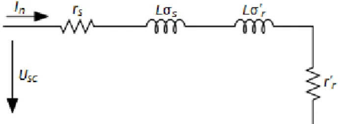
In this case, the rotor is locked, and thus no electromotive force, due to the permanent magnets, is inducted in the stator windings. In addition, the supply voltage must be very low, and so the current in the stator magnetizing inductance, Lm, can be neglected. The LS PMSM
equivalent circuit corresponding to the locked rotor condition can thus be simplified as presented in Figure 6.
Figure 6 – Equivalent circuit model for the LS PMSM under locked rotor condition.
As for the IM locked rotor test, the supply voltage was increased, by means of an auto-transformer, until the supply current reached its rated value, In. The voltage value applied to
the motor is designated as short-circuit voltage, Usc.
3.2.1. Calculation of the leakage inductances
After measuring the current (In), the voltage (Usc) and the phase power (P1) it is possible to
calculate the circuit reactance by [13, 14]: 𝑋𝑒𝑞=
√(𝑈𝑠𝑐∙ 𝐼𝑛)2− 𝑃12 𝐼𝑛2
(1) Since, this motor has deep bars in the rotor cage (class A motor), one can assume that [3]:
𝑋σ𝑠≈ 𝑋σ′𝑟= 𝑋𝑒𝑞
2 (2)
Thus, the per-phase stator leakage inductance is given by [13, 14]: 𝐿σ𝑠=
𝑋σ𝑠
2π𝑓 (3)
𝐿σ′𝑟= 𝑋σ′𝑟
2π𝑓 (4)
3.2.2. Calculation of the rotor resistance
Considering the locked rotor test, the total circuit resistance is given by [13, 14]: 𝑅𝑒𝑞= 𝑟𝑠+ 𝑟′𝑟 𝑠 = 𝑃1 𝐼𝑛2 (5) were the slip (s) is equal to one because the rotor is stopped. Thus:
𝑟′𝑟= 𝑃1 𝐼𝑛2
− 𝑟𝑠 (6)
3.3. No-load test
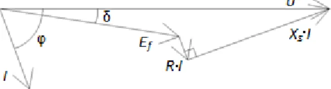
In no-load condition the motor runs at synchronous speed and no current is present in the rotor bars. Based on the phasor diagram of Figure 7 and on the power balance, one obtains the equations system (7), that allows the calculation of the remaining tree unknown parameters, Ef, Xs (synchronous-reactance) and δ (load angle).
Figure 7 – Phasor diagram for motor operation.
{
𝑈 = 𝐸𝑓∙ cos δ + 𝑟𝑠∙ 𝐼 ∙ cos φ + 𝑋𝑠∙ 𝐼 ∙ sin φ 𝐸𝑓∙ sin δ + 𝑟𝑠∙ 𝐼 ∙ sin φ = 𝑋𝑠∙ 𝐼 ∙ cos φ 3 ∙ 𝐸𝑓∙ 𝐼 ∙ cos(φ − δ) = 𝑃 − 3 ∙ 𝑟𝑠∙ 𝐼2
(7)
3.3.1. Calculation of the synchronous inductance
Considering the synchronous reactance (Xs), the synchronous inductance is obtained by:
𝐿𝑠= 𝑋𝑠
2π𝑓 (8)
3.3.2. Calculation of the stator magnetizing inductance
The stator magnetizing inductance is obtained through the synchronous inductance and the stator leakage inductance [13].
𝐿𝑚= 𝐿𝑠− 𝐿σ𝑠 (9)
3.4. Calculation of the back-EMF
The back-EMF obtained in the no-load test is not valid for the all range of operation. In fact, by increasing the load, the magnetic saturation levels of iron decrease causing an increase of the back-EMF. So, the back-EMF is dependent of both load and speed.
As it is well known, usually, the back-EMF is defined by [3]:
where k is a constructive constant of the machine, and Ψ𝑝𝑚 is the flux generated by the permanent magnets.
By measuring voltage, current, and power with different load values, it is possible to define k·Ψpm as a function of Tl, through the analysis of Ef. Note that the value of Xs is already known,
so to determine Ef for other load levels, only the first two equations of (7) are used.
3.5. Mechanical parameters
For the dynamic analysis and simulation of a motor drive, at least two mechanical parameters (moment of inertia – J; friction and ventilation torque - Tfv) are needed to develop the most
accurate model, possible.
3.5.1. Calculation of the moment of inertia
The moment of inertia is a mechanical parameter dependent on the rotor dimensions, given by (10), where m is the mass and r is the radius [11].
𝐽 =1 2∙ 𝑚 ∙ 𝑟
2 (10)
However, in this work, the used value for the moment of inertia was provided by the manufacturer [12].
3.5.2. Mechanical losses
In a rotating machine, mechanical losses are due to friction and ventilation, which are highly dependent on the rotating speed. If we consider only the synchronous speed, the losses due to friction and ventilation can be estimated based on the input power of the no-load test. However, since the proposed model should be valid for a larger speed range, the friction and ventilation torque was obtained by the measurement, at different speeds, of the torque applied to the shaft, considering the no-load test for generator operation. When the generator is in open-circuit, the torque demand is entirely due to the mechanical losses (friction and ventilation).
3.6. LS-PMSM parameters
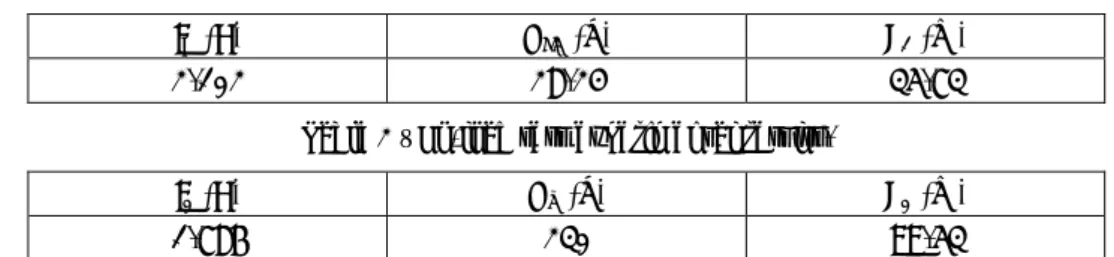
The experimental results obtained for the two most significant tests are presented in Tables 1 and 2.
Table 1 – Locked-rotor test experimental results.
IN (A) USC (V) P1 (W)
2.102 28.24 35.73
Table 2 – No-load test experimental results.
I0 (A) Un (V) P0 (W)
1.786 230 99.53
Thus, based on the proposed methodology, Table 3 presents the motor parameters.
Table 3 - Motor parameters.
𝑟𝑠 4.2 Ω 𝐿σ𝑠 17.077 mH 𝑟′𝑟 3.87 Ω 𝐿σ′𝑟 17.077 mH 𝑘Ψ𝑝𝑚(𝑇𝑙) 0.0472 ∙ 𝑇𝑙+ 0.7744 [V ∙ s ∙ rad−1] 𝐿𝑚 179 mH 𝐽 0.005 Kg ∙ m2 𝑇𝑓𝑣(ω𝑚) 3.93×10⁻⁴ ω𝑚+ 4.57×10⁻² [Nm]
4. Computational model of the LS PMSM
In the presented model all the rotor parameters are referred to the stator, the shaft angular frequency (ω), referred to the electrical angle (ω·t), is related to the shaft angular frequency (ωm) referred to the mechanical angle (ωm·t), by (11), where p is the number of pole pairs.
ω = 𝑝 ∙ ω𝑚 (11)
The LS PMSM dynamic behaviour can be modelled by considering the electric circuits of both stator and rotor, their magnetic coupling and the mechanical interaction between all torques applied to the shaft.
4.1. Matrix representation
Considering both the stator and rotor circuits, one obtains [15-18]. [vabcs ] = [rs] ∙ [iabcs ] + d dt[Ψabc s ] + [e abc] (12) [vabcr ] = [r′r] ∙ [iabcr ] + d dt[Ψabc r ] = 0 (13)
Considering the mechanical balance in the shaft, the mechanical speed is given by [16-18]. 𝜔m= ∫ 𝑇𝑒𝑚− 𝑇𝑙− 𝑇𝑓𝑣− Bω 𝐽 (14) In (12) and (13): [rs] = [ 𝑟𝑠 0 0 0 𝑟𝑠 0 0 0 𝑟𝑠 ] (15) and [r′r] = [ 𝑟′𝑟 0 0 0 𝑟′𝑟 0 0 0 𝑟′𝑟 ] (16)
The back-EMF vector is given by [3]:
[eabc] = √2 ∙ 𝑘Ψ𝑝𝑚∙ ω𝑚∙ [ sin(ω𝑡) sin (ω𝑡 −2π 3) sin (ω𝑡 +2π 3)] (17)
The linkage magnetic flux from stator and rotor can be represented as a function of the stator and rotor currents and the self and mutual inductances, as follows [16-18]:
[Ψabcs ] = ([Lσsabc] + [Lssabc]) ∙ [iabcs ] + [Lsrabc] ∙ [iabcr ] (18) [Ψabcr ] = [Lrsabc] ∙ [iabcs ] + ([Lσrabc] + [Lrrabc]) ∙ [iabcr ] (19) where: [Lσsabc] + [Lssabc] = [ 𝐿σ𝑠+ 𝐿𝐴 𝑀𝐴𝐵 𝑀𝐴𝐶 𝑀𝐵𝐴 𝐿σ𝑠+ 𝐿𝐵 𝑀𝐵𝐶 𝑀𝐶𝐴 𝑀𝐶𝐵 𝐿σ𝑠+ 𝐿𝐶 ] (20)
[Lσrabc] + [Lrrabc] = [ 𝐿σ′𝑟+ 𝐿𝑎 𝑀𝑎𝑏 𝑀𝑎𝑐 𝑀𝑏𝑎 𝐿σ′𝑟+ 𝐿𝑏 𝑀𝑏𝑐 𝑀𝑐𝑎 𝑀𝑐𝑏 𝐿σ′𝑟+ 𝐿𝑐 ] (21) [Lsrabc] = [ 𝑀𝐴𝑎 𝑀𝐴𝑏 𝑀𝐴𝑐 𝑀𝐵𝑎 𝑀𝐵𝑏 𝑀𝐵𝑐 𝑀𝐶𝑎 𝑀𝐶𝑏 𝑀𝐶𝑐 ] (22) [Lrsabc] = [ 𝑀𝑎𝐴 𝑀𝑎𝐵 𝑀𝑎𝐶 𝑀𝑏𝐴 𝑀𝑏𝐵 𝑀𝑏𝐶 𝑀𝑐𝐴 𝑀𝑐𝐵 𝑀𝑐𝐶 ] (23)
Mutual inductances between stator and rotor have the same maximum value (MSr), however, they are dependent on the rotor relative electric position. Thus:
[Lrsabc] = [Lsrabc]T= 𝑀𝑆𝑟 [ cos(ω𝑡) cos (ω𝑡 −2π 3) cos (ω𝑡 + 2π 3) cos (ω𝑡 +2π 3) cos(ω𝑡) cos (ω𝑡 − 2π 3) cos (ω𝑡 −2π 3) cos (ω𝑡 + 2π 3) cos(ω𝑡) ] (29)
Based on the currents and machine inductance, the cage torque, Tcg is given by [16], [18]:
𝑇𝑐𝑔(t) = 𝑝 ∙ [iabcs ]T∙ ( d dω𝑡[Labc sr ]) ∙ [i abc r ] (24)
and the permanent magnets’ torque, Tpm is :
𝑇𝑝𝑚(𝑡) =
𝑒𝑎(𝑡) ∙ 𝑖𝑎(𝑡) + 𝑒𝑏(𝑡) ∙ 𝑖𝑏(𝑡) + 𝑒𝑐(𝑡) ∙ 𝑖𝑐(𝑡) ω𝑚
(25) The viscosity coefficient, B, usually assume small values, so it can be ignored.
4.1.1. Relation between self- and mutual-inductances, and equivalent
circuit model parameters
In equations (12) to (25), used to develop the computational model of the motor, the values of self- and mutual-inductances were used. However, these are not the parameters of the per-phase equivalent circuit.
Let us consider a distributed and perfectly balanced three-phase winding, where:
𝐿𝐴= 𝐿𝐵= 𝐿𝐶 = 𝐿𝑎= 𝐿𝑏= 𝐿𝑐 (26)
and
𝑀𝐴𝐵 = 𝑀𝐴𝐶 = 𝑀𝐵𝐴= 𝑀𝐵𝐶 = 𝑀𝐶𝐴= 𝑀𝐶𝐵 (27)
Considering, also, the synchronous operation of the motor, and the mesh equation of both models, then: 𝐿𝑚 ∂𝑖𝑎 ∂𝑡 = 𝐿𝐴 ∂𝑖𝑎 ∂𝑡 + 𝑀𝐵𝐴 ∂𝑖𝑏 ∂𝑡 + 𝑀𝐶𝐴 ∂𝑖𝑐 ∂𝑡 (28)
Taking into account a balanced three-phase system, thus: 𝐿𝑚= 𝐿𝐴−
1 2𝑀𝐵𝐴−
1
Because of the geometrical displacement between phases of 120º electrical degrees, one obtains [19]: 𝑴𝑨𝑩= − 𝟏 𝟐𝑳𝑨⇒ 𝑳𝑨= 𝟐 𝟑𝑳𝒎 (30) and 𝑴𝑨𝑩= − 𝟏 𝟑𝑳𝒎 (31)
Since LA is related with the magnetic flux that crosses the air gap, and considering the magnetic
fluxes generated in the stator phase A, linked by the rotor phase a, one obtains [19]: 𝑴𝑨𝒂 = 𝑳𝑨⇒ 𝑴𝑺𝒓=
𝟐
𝟑𝑳𝒎 (30)
4.2. Computer modelling of the LS PMSM
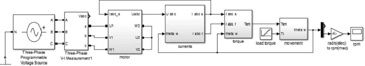
Based on (12) to (25), and the parameters calculated according to (26) to (30), the Matlab Simulink model represented in Figure 8 was used to obtain the expected performance of the motor, by taking into account the empirical parameters of the LS PMSM.
Figure 8 – Matlab Simulink model of the LS PMSM.
5. Experimental validation
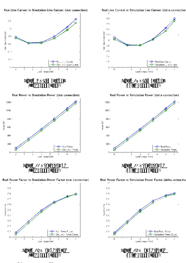
In order to verify the accuracy of the proposed methodology, the motor was tested under different loads levels, in both star (400 V) and delta (230 V) connection. Line current (I1), input
power (P) and power factor (PF) were measured.
These experimental results were compared with the simulation results to validate the experimentally obtained LS PMSM parameters.
The analysis of Figures 9-14 allows us to verify the good match between the simulation results and the experimental ones.
Existing deviations are due to real motor natural unbalances, parameters ignored in simulation, as well as rounded measured and calculated parameters.
6. Conclusion
In this paper an experimental procedure to extract the equivalent circuit parameters of a LS PMSM was proposed.
These parameters were used to define the per-phase equivalent circuit of the LS-PMSM and, based on that, a Matlab Simulink model was developed. This model proved to reflect the behaviour of a real motor allowing for a future study of the motor under unbalanced situations.
Figure 9 – Line current (star connection).
Figure 10 – Line current (delta connection).
Figure 11 – Total power (star connection).
Figure 12 – Total power (delta connection).
Figure 13 – Power factor
(star connection). Figure 14 – Power factor (delta connection).
7. Acknowledgements
The authors acknowledge the support of the Portuguese Foundation for Science and Technology under Project No. UID/EEA/004131/2013 and Project No. SFRH/BSAB/118741/2016.
8. References
[1] Sorgdrager, A., Grobler, A., Wang, R. Design procedure of a line-start permanent magnet synchronous machine. SAUPEC, 2014.
[2] Ugale, R. T., Chaudhari, B. N., Pramanik, A. Overview of research evolution in the field of line start permanent magnet synchronous motors. IET Electric Power Applications, vol. 8, no. 4 (2014), ISSN 1751-8679, pp. 141–154.
[3] P. C. Sen. Principles of electric machines and power electronics. John Wiley & Sons, 1997. [4] V. Bobek. PMSM electrical parameters measurement. Freescale Semiconductor, 2013. [5] Ohm, D. Y. Dynamic model of PM synchronous motors. Drivetech, Inc, Blacksburg, Virginia,
www.drivetechinc.com
, 16 (2000)[6] Kahrisangi, M. G., Isfahani, A. H., Vaez-Zadeh, S., Sebdani, M. R. Line-start permanent magnet synchronous motors versus induction motors: A comparative study. Frontiers of Electrical and Electronic Engineering, vol. 7, no. 4 (2012), ISSN 1673-3584, pp. 459 – 466. [7] Kül, S., Bilgin, O., Mutluer, M. Application of Finite Element Method to Determine the Performances of the Line Start Permanent Magnet Synchronous Motor. Procedia - Social and Behavioral Sciences, vol. 195 (2015), ISSN 1877-0428, pp. 2586 – 2591.
[8] Azari, M. N., Mirsalim, M. Performance analysis of a line-start permanent magnet motor with slots on solid rotor using finite-element method. Electric Power Components and Systems, vol. 41, no. 12 (2013), ISSN 1532-5016, pp. 1159 - 1172.
[9] Isfahani, A. H., Vaez-Zadeh, S. Line start permanent magnet synchronous motors: Challenges and opportunities. Energy, vol. 34, no. 11 (2009), ISSN 0360-5442, pp. 1755 – 1763. [10] Bao, Y., Mehmood, W., Feng, X. Super premium efficiency line start permanent magnet synchronous motor: Design, test and comparison. Petroleum and Chemical Industry Conference (PCIC), Sept 2012, pp. 1–7.
[11] Feng, X., Liu, L., Kang, J., Zhang, Y. Super premium efficient line start-up permanent magnet synchronous motor. XIX International Conference on Electrical Machines - ICEM 2010, Sept 2010, pp. 1–6.
[12] WEG. WQuattro super premium efficiency motor. Tech. Rep., 2011.
[13] Chan, T. F., Shi, K. Appendix H: Experiment 1: Measuring the Electrical Parameters of Motor 3. Applied Intelligent Control of Induction Motor Drives, pp. 397-401, John Wiley & Sons (Asia) Pte Ltd, 2011.
[14] S. Jurkovic. Induction motor parameters extraction. Educypedia-Electronics, 2007. [15] Obeid, N. H., Boileau, T., Nahid-Mobarakeh, B. Modeling and diagnostic of incipient interturn faults for a three-phase permanent magnet synchronous motor. IEEE Transactions on Industry Applications, vol. 52, no. 5, ISSN 1939-9367, pp. 4426–4434, Sept 2016.
[16] Krishna, M. S. R., Ravi, K. S., Fault diagnosis of induction motor using motor current signature analysis. International Conference on Circuits, Power and Computing Technologies (ICCPCT), March 2013, pp. 180–186.
[17] Arkan, M., Kostic-Perovic, D., Unsworth, P. Modelling and simulation of induction motors with inter-turn faults for diagnostics. Electric Power Systems Research, vol. 75, no. 1, ISSN 0378-7796, pp. 57 – 66, 2005.
[18] Wieczorek, M., Rosołowski, E. Modelling of induction motor for simulation of internal faults. Modern Electric Power Systems, Sept 2010, pp 1-6.
[19] Carlos M. C. Santos. Análise e diagnóstico de avarias estatóricas em motores síncronos de ímanes permanentes com arranque direto à rede. Universidade da Beira Interior, 2017.
![Figure 1 - Cross section of a three phase LS PMSM [9].](https://thumb-eu.123doks.com/thumbv2/123dok_br/18823826.927548/2.892.368.524.641.794/figure-cross-section-phase-ls-pmsm.webp)
![Figure 4 – WEG WQuatro LS PMSM , 1.1 kW [12].](https://thumb-eu.123doks.com/thumbv2/123dok_br/18823826.927548/3.892.331.565.779.992/figure-weg-wquatro-ls-pmsm-kw.webp)