UNIVERSIDADE DA BEIRA INTERIOR
Engenharia
3D CFD Simulation of a Cold Flow Four-Stroke
Opposed Piston Engine
Robert Silva Gonçalves
Dissertação para a obtenção do Grau de Mestre em
Engenharia Aeronáutica
(Ciclo de estudos integrado)
Orientador: Prof. Doutor Francisco Miguel Ribeiro Proença Brójo
Dedication
To my parents, for the effort, sacrifices and hard work carried through over these years.
To my fantastic sister for being my constant companion.
For my dedicated grandmother and for my grandfather who did not have the opportunity to witness this important moment of my academic career.
"Simplicity is the ultimate sophistication"
Acknowledgments
I would like to thank, above all, my parents and my sister. Their love and support were crucial for my academic success. I love you very much!
I thank my supervisor, Professor Francisco Miguel Ribeiro Proença Brójo, whom I respect greatly, for all the knowledge, patience, support and time spent during this process. I will forever remember everything you have done for me.
I would also like to acknowledge the ANSYS Support team, with special attention to Mr. Jorge Izquierdo and Mr. Pedro Afonso for their availability. Their help was of great importance.
I wish to thank my soul mate, Sandra Gonçalves, for being so patient, kind and supportive. I love you!
I want to thank all my friends, scattered around the country and the world for being my second family.
Resumo
É realizada uma simulação em CFD de um motor de pistão oposto a funcionar num ciclo de quatro tempos. Pretende-se avaliar o comportamento e as propriedades do escoamento dentro do cilindro, de forma a viabilizar o seu uso a nível comercial. Devido às características inerentes de um motor de pistão oposto, torna-se assim necessário dimensionar o modelo, tendo como referência o motor Jumo 205E: ambas as válvulas, bem como a câmara de combustão e as portas de escape e admissão. Uma câmara de combustão adjacente à zona do cilindro é criada de modo a poder colocar as válvulas. O software comercial Fluent 14.0 é escolhido para realizar os cálculos numéricos. Dada a complexidade do estudo, maioritariamente devido às partes móveis existentes, o uso da malha dinâmica é necessária. O modelo Standard κ− ε é o escolhido para o modelo da viscosidade; as portas de entrada e saída de ar são definidas como
pressure-inlet e pressure-outlet, respetivamente. PISO e PRESTO! são os métodos de cálculo usados
para o acoplamento pressão-velocidade e discretização pressão, respetivamente. Os resultados obtidos não foram os esperados, dado o comportamento e propriedades inadequados do fluido no cilindro e portas.
Palavras-chave
Resumo Alargado
É realizada uma simulação em CFD de um motor de pistão oposto a funcionar num ciclo de quatro tempos . Pretende-se avaliar o comportamento e as propriedades do escoamento dentro do cilindro, de forma a viabilizar o seu uso a nível comercial. Tendo em conta o historial deste motor, é de um grande interesse realizar uma adaptação do mesmo; inúmeros parâmetros obtiveram o seu nível standard devido às caracterícas do motor de pistão oposto. Um motor deste tipo, não tendo cabeça de cilindro, dificulta a tarefa de colocar as válvulas de um modo que o seu funcionamento seja eficiente. É assim necessário dimensionar o modelo, com base no motor de referência Jumo 205E: ambas as válvulas, bem como a câmara de combustão e as portas de escape e admissão.
A construção do modelo, bem como a decomposição, geração da malha e o cálculo da solução são feitos a partir de software comerciais: o CATIA V5 e o ANSYS (o software ANSYS possui várias funcionalidades que permitem realizar as tarefas exigidas). Com a construção do modelo concluída, este é decomposto no ANSYS Design Modeler onde diversas zonas são definidas (oito no total), entre elas o inboard e o vlayer. Estes objetos são colocados junto à superfície superior das válvulas de modo a evitar deformações agressivas na malha. Nomeiam-se as superfícies e zonas para melhor entendimento do modelo. No ANSYS Meshing a malha é criada com um total de 3638149 elementos, onde ambas, malha estruturada e não estruturada, são usadas: a primeira é utilizada nas zonas com formas cilíndricas tais como o cilindro, inboard e o vlayer; a segunda é usada nas zonas com uma geometria mais complexa como a câmara de combustão e ambas as portas. Por fim, a modelação da solução é realizada ao recorrer do software comercial
Fluent 14.0. Standard κ− ε é o modelo escolhido para a viscosidade, bem como o modelo de
energia é ativado. No que toca às condições de fronteira, a entrada de ar é definida como
pressure-inlet e a saída de ar como pressure-outlet. O uso da malha dinâmica é necessário
devido ao movimento dos pistões e das valvulás: todos os três métodos são ativados (layerng,
remeshing e smoothing). A solução usada para o acomplamento da pressão-velocidade é o PISO
e para a discretização da pressão o PRESTO!. São definidos um total de 2440 passos e um valor máximo de 40 iterações por passo, que equivale a 600º.
O resultado obtido não foi o desejado. O comportamento do fluido tanto no cilindro, como nas portas, era inadequado para o bom funcionamento de um motor. A possibilidade de ainda obter bons resultados neste aspecto é credível dada às inúmeras variáveis existentes neste ramo. O uso de motores com volumes mais pequenos será certamente um início para trabalhos futuros.
Abstract
A CFD simulation of a four-stroke opposed piston engine has been performed. It is intended to evaluate the overall behavior and properties of in-cylinder flow, in a way that its use comercialy can be achieved. Due to the inherent characteristics of an opposed piston engine, it is necessary to dimension the model, using as reference the Jumo 205E engine: both valves, as well as the combustion chamber and both exhaust and admission ports. A combustion chamber adjacent to the cylinder zone is placed in order to fit both valves. The commercial software Fluent
14.0 is used to perform the numerical calculations. Due to the complexity of this study, mostly
because of the existence of moving parts, the use o dynamic meshing is necessary. The viscous model is Standard κ− ε; the port entry and exit are defined as inlet and
pressure-outlet, respectively. PISO and PRESTO! are the chosen methods for pressure-velocity coupling
and pressure space discretization, respectively. The final results obtained were far from the expected, mainly due to the inadequate behavior and properties of the fluid within the cylinder and ports.
Keywords
Contents
1 Introduction 1 1.1 Motivation . . . 1 1.2 Main Goals . . . 2 1.3 Task Overview . . . 2 1.4 Historical Review . . . 3 1.4.1 Operating Conditions . . . 6 1.5 Bibliographic Review . . . 82 Basic Theory of Internal Combustion Engine Analysis 13 2.1 Operating Characteristics . . . 13
2.2 In-Cylinder Turbulence and Gas Motion . . . 18
2.3 Intake and Exhaust Flow . . . 20
3 Numerical Modeling and Planning 27 3.1 Governing Equations . . . 27
3.1.1 Spatial and Time Discretization . . . 28
3.2 Turbulence Models . . . 30
3.3 Model Construction . . . 33
3.3.1 Geometry . . . 33
3.3.2 Generation of the Numerical Mesh . . . 35
3.4 Problem Setup . . . 36
3.4.1 Models, Materials and Cell Zone Conditions . . . 36
3.4.2 Boundary Conditions . . . 37 3.4.3 Dynamic Mesh . . . 37 3.5 Solution . . . 39 4 Results 41 5 Conclusions 47 5.1 Future Studies . . . 48 Bibliography 49 A Jumo 205E 53 B Engine Model Details and Schematics 55 B.1 Detailed View of the Valve Gap . . . 55
B.2 Schematics of the Model Engine . . . 56
C Geometry Decomposition and Boundary Naming 57 C.1 Geometry Decomposed . . . 57
C.2 Named Selections of both Cylinder and Chamber . . . 58
C.3 Named Selections of both Vlayers . . . . 59
C.4 Named Selections of both Inboards . . . . 60
C.5 Named Selections of the Admission Port . . . 61
D Mesh 63
D.1 Cylinder Mesh . . . 63
D.2 Chamber Mesh . . . 63
D.3 Port Mesh . . . 64
D.4 Inboard and Vlayer Mesh . . . 64
E Mesh Interfaces, Events, URF's and Dynamic Mesh 65 E.1 Mesh Interfaces . . . 65
E.2 Events . . . 66
E.3 URF . . . 66
E.4 Dynamic Zones . . . 67
F Valve Motion 69
List of Figures
1.1 Schematics of the Wittig Gas Engine, 1879 . . . 4
1.2 Schematics of the Junkers Jumo 205E . . . 6
2.1 The two-stroke cycle stages: 1 - Compression Stroke; 2 - Power Stroke . . . 14
2.2 The four-stroke cycle stages . . . 14
2.3 The Otto cycle . . . 15
2.4 Components and dimensions of the poppet valve . . . 21
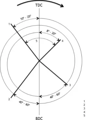
2.5 Valve timing diagram . . . 25
3.1 Schematics of the flathead engine . . . 33
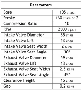
3.2 Domain of the model engine and valve bodies . . . 35
4.1 In-cylinder static pressure . . . 42
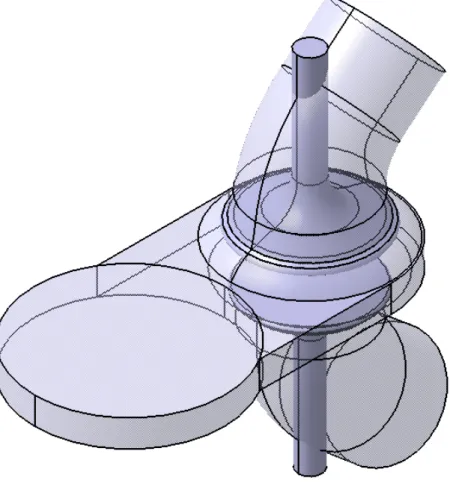
4.2 In-cylinder static temperature . . . 42
4.3 Mass flow rate through the exhaust valve . . . 42
4.4 Mass flow rate through the admission valve . . . 42
4.5 Contours of Mach number at 50º crank angle . . . 42
4.6 Contours of static temperature at 130º crank angle (before exhaust valve opening) 43 4.7 Contours of static pressure at 130º crank angle (before exhaust valve opening) . . 43
4.8 Contours of Mach number at 140º crank angle . . . 43
4.9 Contours of Mach number at 200º crank angle . . . 43
4.10 Contours of static pressure at 270º crank angle . . . 44
4.11 Contours of Mach number at 395º crank angle . . . 44
4.12 Contours of Mach number at 440º crank angle . . . 44
4.13 Contours of pressure at 440º crank angle . . . 45
4.14 Contours of density at 440º crank angle . . . 45
4.15 Velocity vectors at 440º crank angle . . . 45
4.16 Contours of static temperature at 440º crank angle . . . 45
B.1 Detailed view of the valve gap: 1 - Gap; 2 - Valve head; 3 - Combustion chamber; 4 - Port . . . 55
B.2 Schematics of the model engine . . . 56
C.1 Symmetrical view of the decomposed geometry . . . 57
C.2 Named selections of both cylinder and chamber . . . 58
C.3 Named selections of both vlayers: A - Invalve vlayers; B - Exvalve vlayers . . . . 59
C.4 Named selections of both inboards: A - Invalve inboard; B - Exvalve inboard . . . 60
C.5 Named selections of the admission port . . . 61
C.6 Named selections of the exhaust port . . . 62
D.1 Quadrilateral meshing in the cylinder domain . . . 63
D.2 Tetrahedral meshing in the chamber domain . . . 63
D.4 One layer of quadrilateral meshing in the vlayer and a mixture of a greater num-ber of quadrilateral with tetrahedral cells in the inboard (similiar to the exhaust
vlayer and inboard) . . . . 64 F.1 Valve profiles . . . 69
List of Tables
3.1 Model engine dimensions . . . 34
3.2 Mesh sizing values . . . 36
3.3 Mesh skewness metrics spectrum . . . 36
3.4 Orthogonal quality mesh metrics spectrum . . . 36
3.5 Inlet boundary conditon parameters . . . 37
3.6 Outlet boundary conditon parameters . . . 37
3.7 Mesh method parameters . . . 38
3.8 In-cylinder parameters . . . . 38
3.9 Under-Relaxation Factors . . . 40
A.1 Jumo 205E data . . . 53
C.1 Geometry fluid domains . . . 57
C.2 Cylinder and chamber boundary names . . . 58
C.3 Invalve and exvalve vlayer boundary name . . . . 59
C.4 Invalve and exvalve inboard boundary names . . . . 60
C.5 Admission port boundary names . . . 61
C.6 Exhaust port boundary names . . . 62
E.1 Mesh interfaces . . . 65
E.2 Events defined for the dynamic mesh . . . 66
E.3 URF values when reduced . . . 66
E.4 Dynamic mesh: Stationary zones . . . 67
E.5 Dynamic mesh: Rigid bodies . . . 67
List of Acronyms
AMG Algebraic Multigrid Method ARS Algebraic Reynolds Stress
BDC Bottom Dead Center
BMEP Break Mean Effective Pressure BTE Break Thermal Efficiency CFD Computational Fluid Dynamics
CI Compression Ignition
CO Carbon Monoxide
CPU Central Processing Unit DNS Direct Numerical Simulation
EVM Eddy Viscous Models
HC Hydrocarbons
HWA Hot Wire Anemometer
IC Internal Combustion
IDC Inner Dead Center
IGES Initial Graphics Exchange Specification IMEP Indicated Mean Effective Pressure LDV Laser Doppler Velocimetry
LES Large Eddy Simulation LPG Liquefied Petroleum Gas NRC Nuclear Regulatory Commission
OP Opposed Piston
OPOC Opposed Piston Opposed Cylinder
PISO Pressure-Implicit with Splitting of Operators PIV Particle Image Velocimetry
PRESTO! PREssure STaggering Option R&D Research and Development
RAM Random Access Memory
RANS Reynolds-Averaged Navier-Stokes RNG Re-Normalization Group
RSM Reynolds Stress Models
SA Spalart-Allmars
SFC Specific Fuel Consumption
SI Spark Ignition
TDC Top Dead Center
UAV Unmanned Aerial Vehicle
UK United Kingdom
Nomenclature
a Crank offset [m]
Aact Actual area [m2]
Acur Curtain area [m2]
Amin−ex Minimum exhaust valve area [m2]
Amin−in Minimum exhaust valve area [m2]
AP Piston face area [m2]
AR Reference area [m2]
AF Air-fuel ratio [−]
AFact Actual air-fuel ratio [−]
AFsto Stoichiometric air-fuel ratio [−]
B Bore [m]
BM EP Break mean effective pressure [P a]
c Speed of sound [m/s]
cex Speed of sound at the exhaust valve [m/s]
cin Speed of sound at the intake valve [m/s]
cr Compression ratio [−] C Courant number [−] Constant of value 1.3 [−] CD Discharge Coefficient [−] D Diameter [m] Dv Valve Diameter [m] e Total energy [J ]
f Body force per unit mass [N/kg]
F A Fuel-air ratio [−]
F Aact Actual Fuel-air ratio [−]
F Asto Stoichiometric Fuel-air ratio [−]
gx, gy, gz Acceleration (x, y and z, respectively) [m/s2]
IM EP Indicative mean effective pressure [P a]
k Thermal conductivity [W/m· K]
l Piston position [m]
L Stroke [m]
Lex Exhaust valve lift [m]
Lin Intake valve lift [m]
Lv Valve lift [m]
˙
m Mass flow [kg/s]
ma Mass of air [kg]
˙
ma Mass flow of air [kg/s]
mf Mass of fuel [kg]
˙
mf Mass flow of air [kg/s]
M Mach number [−]
n Number of revolutions [−]
N Engine speed [rpm]
Nc Number of cylinders [−]
p0 Downstream pressure [P a]
patm Atmospheric pressure [P a]
pT Upstream Pressure [P a]
P Power [W ]
P r Prandtl number [−]
˙
q Heat flux [W/m2]
r Connecting rod length [m]
R Connecting rod length-to-crank offset ratio [−]
Ideal gas constant [J/K· mol]
Re Reynolds number [−]
RS Reference Size [m]
SF C Specific fuel consumption [kg/W · s]
t Time [s]
T Temperature [K]
T0 Downstream temperature [K]
u, v, w Velocity components according to x, y and z [m/s]
U Velocity [m/s]
UP Piston velocity [m/s]
UPmax Maximum piston velocity [m/s]
VBDC Volume at bottom dead center [m3]
Vc Clearance volume [m3] Vd Displacement volume [m3] ˙ W Work rate [W ] Wb Break work [J ] Wi Indicative work [J ] x Cell length [m]
Xex Vector of exhaust valve angles [−]
Xin Vector of intake valve angles [−]
x, y, z Coordinate system [−]
Z Index Mach number [−]
Greek letters
α Thermal diffusivity [m2/s]
Valve area ratio [−]
β Bore-to-stroke ratio [−]
Diffusion number [−]
ϕ Equivalence ratio [−]
γ Heat capacity ratio [−]
ηm Mechanical efficiency [−] ηV Volumetric efficiency [−] µ Dynamic viscosity [P a· s] ν Kinematic viscosity [m2/s] π Constant of value 3.14159… [−] θ Crank angle [◦]
θIV C Crank angle at closed intake valve [◦]
θIV O Crank angle at opened intake valve [◦]
σ Normal stress [P a]
τ Torque [N· m]
Chapter 1|
Introduction
Chapter 1
Introduction
1.1
Motivation
The Opposed Piston (OP) engine was initially designed in the late 1800’s in Germany as an alternative to the existing engines of the time, such as the Otto engine, and was well known for its versatility and simplicity in numerous applications which included aircraft, ships, tanks, locomotives, automobiles and stationary [1]. Even though the OP concept could be applied to both two and four-stoke diesel engines, the two-stroke cycle was predominant, probably for simplicity reasons, while the most noticeable four-stroke OP engine was built by a French manufacturer, Gobron Brillié, and was used as a racing engine, around 1900.
The advantages presented by the two-stroke OP engine were so great, that several records, which were established at the time, are yet to be equaled. These records have set the regular standards which are still used today for power-to-weight ratio, dynamic refinement, fuel tol-erance, package space, fuel efficiency and manufacturing simplicity. The advantages involved many important aspects which significantly improved the performance of the engine overall; ease of manufacture, excellent balance, fuel efficiency, outstanding specific output, high spe-cific torque, very high power density and power-to-bulk ratio. Also, two-stroke cycles presented greater benefits compared to the conventional four-stroke engine: heat transfer reduction with fewer loss in engine friction and mechanical durability, reduction of the number of cylinders, therefore reducing the surface area, effective stroke-to-bore ratio could be done without com-promising piston speed, very reliable, low maintenance, excellent multi-fuel tolerance, low injection pressures along with simple fuel injection nozzles and a very low part count.
With the implementation of emission regulations in the mid-20th century, the rise of the OP
engine came to a halt, mainly due to oil consumption and high emission problems, allowing the conventional four-stroke engine to develop further. Among the typical challenges which two-stroke engines faced, the main issues involved lubrication of the small-end bushes and piston-pin bosses, port traversing by the rings, side injection and torsion vibration. In four-stroke OP cycle engines, the most difficult challenge, in addition to the problems presented by the two-stroke cycle engine, was still the location of the admission and exhaust valves, which will be one of the topics covered in this study.
The OP engine is still used in many unconstrained emission level applications; however, with the increasingly tighter emission regulations, the technology available today, along with the different manufacture processes and larger number of solution possibilities, many of the prob-lems regarding the OP engine could be overcome and a wider field of application may appear. Therefore, it is of great interest to focus on this subject in order to develop and improve Internal Combustion (IC) engines, and perhaps re-launch the OP engine.
Chapter 1|
Introduction
due to its power-to-weight ratio, a very important factor in aeronautic projects. Even though only lighter aircraft would benefit more from the OP engine, the applications are numerous. Unmanned Aerial Vehicles (UAV) are a perfect example of a low-risk possibility to apply the OP engine, for both fixed- and rotating-wing aircraft, powered gliders and ultralight aircraft. Despite being a good alternative for future UAV’s, the widely used two-stroke Boxer engine still remains a strong competitor in the 8 kW range field. In 80 kW UAV’s statistical analysis by comparing the OP engine with the Wankel engine shows a slight advantage of the OP in several aspects, such as fuel efficiency and estimated cost. In addition, the size of the OP engine is 20% smaller than the Wankel and possesses a bulk four times greater.
Despite the importance of the IC engine to society, it has a great impact on the environment and on public health, which worsens with the increase of the already vast number of motored vehicles. A rapid solution is therefore necessary, not only for these reasons but also due to the limited fuel reserves. During the last century, the IC engine efficiency has been improved greatly, however it is well documented that it is still inefficient and therefore, possible solutions are being developed, yet unsuccessfully. The Nuclear Regulatory Commission (NRC), concluded that the IC engine will most likely be the prime mover for the next years, possibly decades. Thus, it is important to continue Research and Development (R&D) in this area, in order to better understand its fundamental processes affecting engine efficiency and the production of undesirable emissions [2].
1.2
Main Goals
Engineering tasks, such as structural and fluid analysis, have become simpler due to the appear-ance of computational software, improving the way of how engineers face obstacles: it is more economical, the analysis can be done faster, results are less prone to errors and, if necessary, adjustments can be performed quickly.
The present work focuses on the construction of a four-stroke OP engine model, based on the Jumo 205E engine, followed by a numerical analysis using Computational Fluid Dynamics (CFD) tools, with the purpose of verifying its reliability of the selected valve positioning and engine geometry. Also, port flow behavior is studied in order to understand the influence of the port design during admission and exhaust processes.
1.3
Task Overview
In the present chapter, the author expresses his motivation behind the development of this the-sis, presenting what is intended to be achieved and the reasons which led to it. The objectives for this study are also outlined and presented in a brief review regarding the OP engine as well as its operating mode. Finally, a bibliographic review is presented, focusing on other works related to the subject and pointing out their importance in this area.
In chapter 2, the basics of the IC engine analysis are discussed, such as the basic operating parameters. The effects of turbulence on different aspects during each cycle and the behavior of the gas during the exhaust and intake processes are also discussed.
Chapter 1|
Introduction
Chapter 3 provides a deeper insight into the government equations of CFD analysis; the ap-propriate turbulence models are also discussed. The construction of the geometry in study is explained, as well as the generation of the mesh and dynamic mesh used for the simulation. Boundary conditions are imposed and the solution method is chosen.Chapter 4 presents the numerical results obtained by the CFD simulation. The results are explained in detail and discussed throughout this chapter. Possible problems encountered in this thesis are mentioned as well.
Chapter 5 presents the conclusions from the simulation in CFD and provides suggestions for future work.
1.4
Historical Review
In the mid-19th century, the development of the IC engine was based on single-cylinder
en-gines and both two- and four-stroke enen-gines, which offered simplicity and higher efficiency. The OP concept initially offered an attractive way of achieving a very dynamic and balanced single-cylinder engine that eliminated the need for cylinder-head joints and avoided the chal-lenges in manufacturing a monolithic cylinder with cylinder-head barrel. The “double” stroke presented another significant advantage – the possibility of large-cylinder displacements with small-cylinder bores, reducing gas loads on the crankshafts. The development of the OP engine can be divided into three main periods: pre-1900, from 1900 until the end of World War II in 1945 and from then on.
1874 - 1900
In 1874, Giles of Cologne built an OP, single-cylinder engine with one of the pistons connected to the crankshaft, while the other was a free piston. The crank-driven piston would induce a fresh charge from a cam-actuated inlet port, located approximately mid-cylinder. The charge would then ignite partway through the expansion of the crank-driven piston, causing a rise in pressure and the retraction of this piston, while the free piston would be displaced until its end stop, being then retained by a controlled clutch in order to drive out the exhaust products. Although a large amount of these engines were produced, they were never commercially successful, especially due to the thriving Otto four-stroke engine.
The production of the first OP engine with both pistons being crank-driven is ascribed to Wit-tig. Even though this has not been proved [3], Wittig did introduce the classical three-throw crank, where the center throw is linked to the inner-piston (closest to the crankshaft) and both outboard throws, phased at 180º relatively to the center throw, are linked via rods to the outer-piston (furthest from the crankshaft), as shown in Fig. 1.1. Admission and exhaust were done by ports located in the middle of the cylinder and operated on a four-stroke basis. The most significant advantage of this concept was the cancellation of forces acting on the main bearings, as a two-piston system respects Newton’s 3rd Law of Motion, producing essentially equal and
opposite net gas and inertia forces.
Chapter 1|
Introduction
Figure 1.1: Schematics of the Wittig Gas Engine, 1879 [4]
had a large flywheel (a large wheel, mounted on the crankshaft whose function is to maintain its speed constant, by storing the excess energy from the power stroke, being later returned during the next stroke [5]) and the lower crankshaft had several gearing arrangements enabling it to move in a prescribed manner relative to the upper crankshaft. Being a two-stroke engine, it became unique due to the non-existence of scavenging (in the traditional four-stoke sense) and induction was achieved by positive displacement of both pistons.
In 1892, Robson of Sunderland presented a variant of the Wittig engine, in which the cranks were arranged differently in order to avoid both pistons reaching their dead centers simultaneously. This concept was very close in principle to the famous Oechelhaeuser and Doxford that would be developed, also in Sunderland, 20 years later.
The most notable breakthrough in the subject before 1900 was definitely the two-stroke OP gas engine developed by Hugo Junkers and Oechelhaeuser in 1892, at the Gas Engine Research Institute. The output of the 3 l engine was 84.3 kW at 160 rpm, with a mechanical efficiency of 77%. This was, and still is, an astonishing achievement, while simultaneously fuel consumption was reduced by 40% when compared to the contemporary four-stroke engine. By the end of the century, the advantages of the concept became obvious: simplicity, light mechanical loading of the crankshaft, balance and the no need for a cylinder head joint.
Chapter 1|
Introduction
1900 - 1945
The development and research of the OP engine before 1900 was a success, and the years from the beginning of the 20thcentury until the end of World War II also witnessed several
achieve-ments, initially marine and stationary, and later on in aviation. Many people participated in these achievements. Among them was R. Lucas with the introduction of many conceptual as-pects and the notable importance given to the crankcase compression pressure, which minimized the crankcase volume.
Beardmore & Oechelhaeuser also played an important role in the development of OP engines with numerous features, such as the location of the oil scraper rings on the cylinder bore, consequently reducing the overall height of the engine. Further variants enabled overall height reduction (35% lower than the traditional Oechelhaeuser engine), reduced pump losses, inertia loads, higher speeds and mass of moving parts even though these engines would often suffer connecting rod fractures.
Fullagar developed the gas engine and improved OP packaging and weight reduction. Despite the reliability of these engines, their performance at certain speeds was not the desired one and regardless of all rectifications, this project was dismantled along with several others. The Fullagar concept was later applied to the 115 Q and R engines, remaining in service for 15 years with no severe faults, with high Break Thermal Efficiency (BTE) and being highly acknowledged for their simplicity, robustness, efficiency and longevity.
Hugo Junkers, already referenced, developed the tandem engine and was involved in various engine applications. In the field of aeronautics, special attention was given to the Fo2, and later to the Mo3. Both, despite their success, were destroyed as a result of the conditions imposed by the Treaty of Versailles in 1918. Afterwards, Junkers manufactured the Fo4, a derivation of the Fo2, and after a series of developments, Jumo 4 appeared, being later renamed as Jumo 204. Until the beginning of World War II, Junkers suffered an evolutionary period, focusing mainly on aero engines and, amongst several models, the Jumo 205 (Fig. 1.2) and 207 entered production, with the 205 becoming the first engine for commercial applications and the 207 being used in high-altitude applications.
Doxford’s OP engines had a big impact on the marine sector, but eventually proved to be inapt for the industry. D. Napier had a significant impact on the engine business, especially with the Napier Lion, which powered World War I aircraft and naval powerboats (W12 Napier Lion), and he established a world record in speed set by the Gloster VI Seaplane with a top speed of 565.36
km/h, in 1929. Other engines were later manufactured and widely used in World War II, such as in the Mustang and Typhoon fighter aircraft. Finally, the Sulzer brothers took an attempt on OP engines; however, they were unsuccessful due to the large engine height required to operate at very low marine speeds.
1945 - Today
After World War II, the OP engine unexpectedly experienced the most fruitful manufacturing period, especially with United Kingdom (UK) companies, despite the fact that its use reduced dramatically. This period brought the equilateral triangle arrangement - a Napier Deltic design,
Chapter 1|
Introduction
Figure 1.2: Schematics of the Junkers Jumo 205E [6]
the K60 and K60T from Rolls Royce Motors and more recently, the Diesel Air Engine – Air Airship Industries. Among these, the Opposed Piston Opposed Cylinder (OPOC) has received very posi-tive feedback from most industries. Reference [3] provides an excellent insight into OP engines regarding this period for those who desire to extend their knowledge in this subject.
1.4.1
Operating Conditions
Normally, OP engines are characterized by a pair of pistons operating in a single cylinder, elim-inating the need of cylinder heads, with slight variations in the disposition of the engines’ com-ponents. There are several types of OP engines, essentially five, with many variants which will be briefly described.
The Crankless OP Engine
The crankless OP engine, also known as the free piston engine, commonly displays its pistons in a single-cylinder with the necessary space between them for combustion. Both pistons are con-nected to a pneumatic spring or a bounce chamber, allowing them to return to their Inner Dead Center (IDC), after combustion and expansion. The engine starts with the help of compressed air and the bounce pistons need air replenishment in order to maintain the minimum pressure levels required. There is no more further information about this variation of engine.
The Single-Crank OP Engine
The next type of OP engine is the Single-Crank OP engine, which has two main variations: the three-throw crankshaft (Wittig) and the folded rockers. As mentioned in the previous section (Sec. 1.4), the first OP engines produced in 1878 used the first type of arrangement mentioned above: a single three-throw crankshaft in which three connecting rods, each phased at 180º from each other, connected to both pistons. The central rod drove the “inner” piston (which
Chapter 1|
Introduction
was closer to the crankshaft), while the remaining side rods drove the “outer” piston (which was farther from the crankshaft).The rotating movement of the crankshaft moved both pistons in order to produce the equivalent linear movement seen in normal piston engines. Numer-ous benefits were obtained from this arrangement, namely the fact that the moving parts and the cylinder liner contained all of the gas and inertia loads, which resulted in practically no transmission of these loads, other than the torque reaction forces to the engine frame or the main bearing. This advantage allowed the engine to be relatively lightweight due to the light crankcase. The downside of this arrangement led to a longer crank, when compared to other equivalent-displacement single-cylinder OP engine arrangements.The folded rockers OP engines had a completely different design when compared to the previous variation. The pistons were connected to a single crankshaft by combining several rocking beams, which were essentially pivoted levers with an articulated joint. In this case, the rockers were subject to large bending loads, thus the rocker shafts that supported the rockers needed to withstand the extensive loads by using strong tensile elements, such as crossbolts. Similarly to the single-crank OP engine, all loads were carried by the cranktrain and the crossbolts, resulting in a relatively light crankcase once again. This, along with the folded arrangement, allowed the overall size of the engine to be reduced significantly, in some cases about 50%.
The Double Crankshaft OP Engine
The double-crankshaft OP engine, introduced by T.H. Lucas (Sec. 1.4), brought an advantage in relation to the single-crankshaft OP engine by presenting more compact inline arrange-ments. Both crankshafts were connected by spur gears, bevel gears and lay-shafts, or chain drives. By comparing basic height and length of the twin-crankshaft arrangement with the single-crankshaft layout, the latter presented a height 15% lower than the twin-crankshaft, but had an increase of length by 250% for the same displacement. The ratio of their bore di-mensions was taken into account in this comparison. Depending on the application desired, the single-crankshaft layout tended to be less favorable than the twin-crankshaft arrangement, mostly due to adverse torsion vibration characteristics. However, a new concept of the single-crankshaft has been studied, the OPOC, which reduces the above mentioned length disadvan-tage. A multiple-crankshaft OP engine is another variant which is essentially a combination of multiple twin-crankshafts in various geometric forms (triangle, square or star).
The Rotary OP Engine
A more improbable variation is the rotary OP engine, where the pistons are somewhat like paddle blades and oscillate about a central output shaft, while the whole assembly is contained in a cylindrical housing that holds the combustion and gas-exchange systems. In some cases, the pistons orbit as well as oscillate and can perform either two-or-four-stroke cycles with appropriate ports.
The Barrel OP Engine
Finally, the barrel cam engines function in a way that the cylinders are parallel to the crankshaft axis and the pistons engage with a cylindrical cam track, which forms part of the crankshaft.
Chapter 1|
Introduction
Aeronautical OP Engines
During the 20th century, several aeronautical OP piston engines emerged; however, only two
variations had an important impact on this area: the Junkers Jumo 205 and the current Diesel Air Engine. The Jumo 205, also used in military applications, is still considered the most effi-cient aero piston engine in aviation, as it was the only diesel engine used regularly in aircraft service and was produced in large quantities. It is based on a vertical liquid-cooled light-alloy cylinder arrangement with two crankshafts driving the upper exhaust pistons and the lower air pistons. The air crankshaft drives a geared centrifugal blower which supplies scavenge air and the exhaust crankshaft drives the airscrew; fuel injection pumps for each cylinder are activated by two camshafts located at the center of a set of five spur gears which are connected to both crankshafts. The coolant pump, lubrication oil pressure and scavenge are controlled by a single shaft at the rear of the air crankshaft with each of the low-oil pressure fuel pump systems being driven off the rear end of each camshaft. The two inlet manifolds are integrally casted with the cylinder block and its entries are located on the rear face of the crankcase and connected with the twin outlets of the centrifugal blower. The liner is considered the best component of all components of the engine in terms of design, materials, finish and its contribution for engine performance and durability.
1.5
Bibliographic Review
For decades, understanding in-cylinder flow has been a great challenge for engineers due to the great number of events taking place in a very short period of time. In order to analyze and study these events, several techniques are often used, such as Hot Wire Anemometer (HWA), Laser Doppler Velocimetry (LDV) and Particle Image Velocimetry (PIV). These techniques, however, have their limitations and are very expensive - better results are proportional to greater costs. An excellent review of these methods is done by [7], where both advantages and limitations are explained in detail. With the emergence of new tools, such as CFD, IC engine analysis took a step forward. It is important to know that despite all its advantages, the user must be aware that CFD results are only predictions and can be, at times, far from accurate [8]. Both experimental data and numerical simulations should be used together in order to make better decisions regarding the outcome of the project. Nevertheless, when used correctly, CFD can be a very important and helpful tool, which can be noticed in the increasing number of studies performed in turbo machinery with its use.
The number of numerical simulations studies of IC engines is very vast and have numerous ap-proaches. Unfortunately, no study involving four-stroke OP engines has been found and, thus, this section will mainly focus on the numerical aspect of the studies and their results in order to have a baseline to know what to expect from the OP engine.
Regarding OP engines, in 2010, [9] performed a three-dimensional computational study of scav-enging performance in a two-stroke OP engine. Two models were studied: the first with two admission ports and one exhaust port; the second model had four admission ports and one ex-haust port. Both models were built symmetrically in order to reduce the number of cells which were 29298 and 112667 cells, respectively. Fluent was the software of choice to perform the simulation. Standard κ− ε was selected for the viscous model, PRESTO! and PISO for the
pres-Chapter 1|
Introduction
sure discretization and pressure-velocity coupling, respectively. As for the boundary conditions, the intake was defined as pressure-inlet whereas the exhaust as pressure-outlet.The authors concluded that, for both cases, the best intake pressure for optimum scavenging was 1.1 atm and for the same admission pressure the second model presented better scavenging efficiency, delivery ratio and trapping efficiency.
Still regarding OP engines, [10] performed a computational study as well in this field, in 2012. A single cylinder, two-stroke OP engine simulation was done in order to understand scaveng-ing performance at different scavengscaveng-ing pressures and engine performance at full load. The supercharged engine model possessed two ports: one admission and one exhaust opposed to each other. Boundary conditions are calculated by Matlab, whilst the gas flow is computed by the one-dimensional commercial code GT-Power. A cylinder with one piston is modeled, with the same bore as of the OP engine model, as well as an equivalent single piston motion profile to assure that the expanding work stayed invariant. Heat and combustion processes are also included in the study.
The analysis showed that engine speed in OP engines has a strong influence in volumetric ef-ficiency and mass flow rate, as well as the occurrence of backflow. Volumetric efef-ficiency in-creased with engine speed, however started to decrease when engine speed reached 2000 rpm. Also, the greater the engine speed value, more likely it is to occur backflow. Both pressure and temperature profiles showed to be very similar to conventional engines.
With respect to numerical studies of OP engines, the review has been concluded. The following reviews are related to other aspects of in-cylinder analysis.
On the subject of CFD modeling of in-cylinder analysis, [11] presented a study on general Fluent modeling of an IC engine. In this paper the author studied the tutorial model offered by ANSYS in order to predict in-flow movement, with no combustion, by using the In-Cylinder model of the referred software. Using the ANSYS Workbench capabilities, the geometry was decomposed into 6 fluid zones, each one with their own mesh type and size. Cells were placed in a region considered as the minimum valve lift in order for the solution to function properly. Also, events were created at defined moments of piston motion. Likewise the first review, pressure-inlet and
pressure-outlet were chosen for intake and exhaust boundary conditions, respectively. Standard κ− ε was chosen for the viscous model and PISO was used as the pressure-velocity coupling
scheme. The time-step was set to 0.25º for this case and decreased during valve openings to 0.125º. Finally, initial engine temperature was defined as 300 K since it was considered that the engine was naturally aspirated.
It was concluded that the software can perform effectively all four-strokes of the IC engine, giving good detail on air mixing and turbulence, as well as accurate temperature and pressure profiles.
[12] used Fluent as well, in order to study the performance of a three-dimensional two-stroke Spark Ignition (SI) engine. Based on experimental results, the author was able to compare those with the numerical results and verify their accuracy. Half the model was used due to symmetry of the geometry, leading to a great reduction of cells and time. Layers of hexahedral cells are created near the moving parts, whereas the remaining stationary zones have tetrahedral ele-ments. Using the remeshing, layering and smoothing capabilities of Fluent, a transient solution
Chapter 1|
Introduction
is possible. The fluid used for the simulation is air whose density is calculated by the
ideal-gas-law and the viscous model is Standard κ− ε. The species transport model is also activated in
order to define 2 types of phases: burned and unburned. The intake boundary condition was defined by experimental results, by using a pressure profile in function of the crank angle. The pressure interpolation was calculated by PRESTO!, the PISO algorithm was used for the pressure-velocity coupling method and the Second-Order Upwind Scheme was chosen for the discretization of all variables.
The results showed that the greater the engine speed the higher the cylinder pressure would be and at certain crank angles, due to greater exhaust pressure, backflow would occur. The author advises that improvement in the Algebraic Multigrid Method (AMG) solver is needed in order to enable simulations which use accurate fuel characteristics.
The study of IC engine combustion is, as well, a matter of great interest, as presented by [13] in an attempt to reduce emissions of a medium capacity two-stroke IC engine with stratified scavenging system. The validation of the obtained results was based on the outputs of a single two-stroke cylinder engine, with an alteration in the basic design by adding another port in the air supply system.
The model is created using CATIA, meshed by Gambit and exported to Fluent. The mesh pos-sesses approximately 187000 elements. All three basic equations are solved (conservation of mass, momentum and energy); chemical analysis is also included in the analysis. The inlet and exhaust boundary conditions are defined as velocity-inlet and pressure-outlet, respectively. The modification made to the engine improved performance, scavenging and trapping efficien-cies, the last two being strongly affected by delivery ratio. The analysis also gave a reduction of Hydrocarbons (HC) emissions by 34-38% and Carbon Monoxide (CO) emissions by 22-25%
Other types of software are available to perform IC engine simulations, such is the case of [14], in which the authors use a KIVA-3 code based numerical model to study a three-dimensional transient intake flow through a port-valve-cylinder system of a high-speed small motorcycle engine. Dynamic grid generation became the crucial point in order to perform the transient study, since piston and valves move, the mesh begins to stretch resulting in bad meshing and, consequently, bad results. Similarly to nowadays solution (in Fluent), a plane would be removed during the piston movement towards the Top Dead Center (TDC) and a ghost plane would be inserted when the piston moved towards the Bottom Dead Center (BDC). With this method, it was possible to do the same for the valve movement allowing an effective transient simulation. The intake boundary condition was assumed as pressure-intake and all walls had a
fixed-wall-temperature condition.
Both velocity and pressure parameters were analyzed. During the intake process, shortly after the the intake valve opens, it is noticed that during a 40º crank angle gas enters the intake port from the cylinder. This occurs due to the pressure difference, which rapidly diminishes and by the time the valve is closed, pressure inside the cylinder is slightly greater than in the port. The software used allows the user to perform transient IC engine solutions for both vertical and inclined valves and provided a good theoretical basis for optimizing engine port designs.
Different cases of IC engine analysis may require different approaches, as presented by [15]. Three engine simulations were performed in this study, in which results were compared with the respective simulation time: uni-dimensional, quasi-dimensional and CFD. The expansion cycle
Chapter 1|
Introduction
of the high speed diesel engine was analyzed running under different motoring conditions and engine speeds.The uni-dimensional showed to be very little time consuming, taking as long as 1 s to perform the simulation. It also calculated, with reasonable accuracy, the in-cylinder pressure; the same can not be said about in-cylinder mean gas temperature, which the software underestimates when compared to the other two models.
On the other hand, the quasi-dimensional analysis was capable of providing good results regard-ing local in-cylinder temperature distribution, as well as the qualitative effect of the cylinder geometrical design on in-cylinder flow and temperature, when compared to CFD results. With a computational time of 6 min, the quasi-dimensional model calculated the cylinder pressure more closely to the measured results than the uni-dimensional model. Additionally, the calcu-lated heat transfer process through the cylinder walls is nearly the same as the CFD case results. The author concluded that this model may be useful as a preliminary study of the effect that the combustion chamber geometry has on the physical processes occurring within the cylinder, whereas the uni-dimensional model cannot perform this task since it does not take in account the design of the chamber.
The CFD model has greater capabilities of calculating detailed flow-fields for different engine designs as well as various physical processes, even though the calculation time was approxi-mately 20 h.
For parametric cases, it was advised to perform a quasi-dimensional study first, in order to determine the limited number of cases of interest and then apply those cases on a CFD code for more detailed information.
As the previous case, CFD simulations of IC engines can be very time consuming, with some sim-ulations taking months to complete. This is a problem for many entities, thus [16] developed a set of software tools, in order to reduce these simulation times, for IC engine flows and com-bustion. The author presents very good and detailed information on simulation setup, meshing and problems existent.
Chapter 2|
Basic Theory of Internal Combustion Engine Analysis
Chapter 2
Basic Theory of Internal Combustion Engine
Analysis
2.1
Operating Characteristics
Every reciprocating engine, with the exception of the Wankel engine, operates in a similar way; the linear movement of a piston in a cylinder, due to confined and controlled explosions of a gaseous mixture, is transformed into rotational movement of the crankshaft which transmits the energy created by the explosion to a shaft and then to the components that generate vehicle motion. In order to obtain a fully functional engine, it is necessary to complete four steps: admission of a fresh mixture of fuel and air; compression of the charge in order for temperature and pressure to rise; explosion of the mixture, creating the energy needed to move the piston; and exhaust of the burned mixture.
Types of Ignition: Compression and Spark Ignition
The explosion of the mixture can occur in two distinct ways; by compression, also known as Compression Ignition (CI) and by external ignition or SI. In the first case, the gaseous mixture auto-ignites due to the rise of pressure and temperature during the compression stroke. The SI engine needs an external source, such as a spark plug, which, when near the TDC, releases a small electric charge to the mixture, igniting it.
Two-stroke & Four-stroke Cycles
There are two types of engine cycles: two-stroke and four-stroke. A stroke is the displacement of the piston from the TDC to the BDC and back. A cycle is completed after two strokes (one crankshaft revolution), meaning that in a two-stroke engine one cycle is necessary in order to conclude to entire process and in a four-stroke engine, two cycles are needed. The two-stroke can be explained with reference to Fig. 2.1.
1. Normally known as the compression stroke, the piston travels from the BDC to the TDC compressing the confined charge, which is sucked into the cylinder due to pressure differ-ence. Usually, in this type of engine, the charge is mixed before entering the cylinder, also referred to as pre-mixed. However, if this is not the case, the fuel can be injected into the cylinder when the piston is near the TDC and, subsequently, the explosion occurs. In this stroke, two of the four necessary steps mentioned above are performed: compression and explosion;
2. The second phase is called the power stroke, in which the piston moves towards the BDC due to the rise of temperature and pressure. On the cylinder walls, there are cavities, called ports. These cavities are unveiled by the movement of the piston; as the piston descends, the exhaust port is uncovered, allowing the burned charge to escape. The
Chapter 2|
Basic Theory of Internal Combustion Engine Analysis
downward motion continues, revealing, afterwards, the inlet port, through which a fresh charge is allowed to enter. The last two steps are completed in this stroke: admission and exhaust. The process then restarts.
Figure 2.1: The two-stroke cycle stages: 1 - Compression Stroke; 2 - Power Stroke [17]
The four-stroke needs an extra revolution in order to complete the process. While the two-stroke engine performs two steps in one two-stroke, the four-two-stroke engine performs one step in each of its four strokes. Also, the gaseous mixture is controlled by a set of valves: the exhaust and admission valves. Normally, there is one of each; however, it is common to have more in recent engines. The process is as follows and is represented in Fig. 2.2.
Figure 2.2: The four-stroke cycle stages [18]
1. With the piston at the TDC, the admission valve opens allowing the fresh charge into the cylinder. This happens due to the downwards movement of the piston, creating a difference in pressure and, consequently, a suction effect of the exterior air into the cylinder. This completes the first step: the intake stroke;
Chapter 2|
Basic Theory of Internal Combustion Engine Analysis
2. The following step is the compression stroke, in which, similarly to the two-stroke, thecharge is compressed and the explosion occurs before the piston reaches the TDC; 3. After the explosion, the piston is pushed downwards towards the BDC, due to the increase
of pressure and temperature. This is called the power stroke;
4. Finally, the piston moves upwards in order to expel the burned fumes caused by the ex-plosion. The exhaust stroke thereby completes the full process.
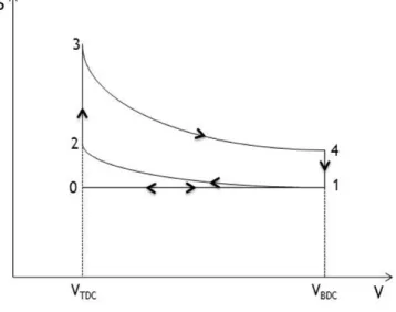
Thermodynamically speaking, all four-stroke SI engines work on the Otto cycle, which is rep-resented by the P-V cycle in Fig. 2.3. It is composed essentially of four internally reversible processes:
Figure 2.3: The Otto cycle
• 1-2 – Isentropic compression
• 2-3 – Constant volume heat addition • 3-4 – Isentropic expansion process • 4-1 – Constant volume heat rejection
There are two additional steps which do not appear in the theoretical Otto cycle [19]:
• 0-1 – Intake process • 1-0 – Exhaust process
Fuels
Like any power unit, an IC engine requires a constant input of energy to produce work; this energy is extracted from the combustion of hydrocarbon fuels with air, during the process of converting chemical energy from the fuel into internal energy of the air molecules. Nowadays there are several fuels available, such as gasoline, diesel, crude oil and other derivatives, natural gas, Liquefied Petroleum Gas (LPG), propane, alcohol, methanol, ethanol and hydrogen. Carbon
Chapter 2|
Basic Theory of Internal Combustion Engine Analysis
and wood are solid fuels also widely used. From a more ecological point of view, biomass is becoming increasingly used due to the increase of fuel prices and environmental pollution.
Engine Parameters
During the process of an IC engine design there are several parameters and variables that should be considered in order to optimize its performance. Important factors, among others, are the dimensions of the engine, such as bore and stroke, which have a significant influence on the engine’s overall performance and output.
For a given crank offset (a), the stroke (L) of an engine can be calculated by Eq. 2.1:
L = 2a (2.1)
The bore-to-stroke ratio – Eq. 2.2 - is an excellent parameter to evaluate the engine’s design. It usually has values in the range of 0.8 and 1.2, and offers a better insight of some parameters such as friction losses, thermal efficiency and piston speed. Connecting rod length-to-crank offset ratio (Eq. 2.3) is, as well, a recommended geometrical parameter to take into account, with values varying between 3 and 5, for small and medium engines, and 5 to 10 for larger engines.
β = B
L (2.2)
R = r
a (2.3)
Piston speed is also a factor not to be taken lightly; considering that the piston is accelerated and decelerated in each stroke, the material of the piston and connecting rod are subjected to incredibly high forces. Therefore, it is common to impose a safety limit in piston speed, varying between 5 and 15 m/s. Also, the gas flow within the cylinder suffers with the increase of piston speed; the higher the speed, the less time the intake and exhaust valves are open and subsequently, the mass flow rate must increase. Consequently, this may lead to an inability of the engine to introduce the necessary quantities of air in such a short time [20]. The average piston speed, considering a given engine speed (N ), can be calculated by Eq. 2.4:
Up= 2LN (2.4)
For analytical purposes, it is useful to calculate the position of the piston (l) (Eq. 2.5) at a given crank angle (θ) and connecting rod length (r):
l = a cos θ +√r2− a2(sin θ)2 (2.5)
A very common performance indicator is the volume of displacement (Vd), presented in Eq. 2.6. In other words, the volume the piston dislocates from the BDC to the TDC.
Chapter 2|
Basic Theory of Internal Combustion Engine Analysis
Vd=
π
4B
2L (2.6)
There is a remaining volume when the piston reaches the TDC which is called the combustion chamber or clearance volume (Vc). Therefore, the total volume of the cylinder when at the BDC is Eq. 2.7:
VBDC = Vd+ Vc (2.7)
Eq. 2.8 shows the compression ratio (cr), which is also an important parameter in IC engine design. CI engines have compression ratios in the range of 20 to 70, in extreme cases, while SI engines vary from 8 to 11.
cr=
Vc+ Vd
Vc
(2.8)
Work, torque and power are three of the most important output parameters in any IC engine. Work is the result of pressure with the variation of volume; however, it is usually considered the Indicative Mean Effective Pressure (IMEP), also an excellent comparison parameter since it is independent of the size of the engine. Size is, in fact, associated to torque, whereas the speed of the engine is linked to power. IMEP is a measure of the indicated work done by the gas on the piston per unit of swept volume (Eq. 2.9 ):
IM EP = Wi× Nc× n Vd
(2.9)
However, the Break Mean Effective Pressure (BMEP) presented in Eq. 2.10 is more relevant, since it is measured using a dynamometer and leads to a similar equation as Eq. 2.9:
BM EP = Wb× Nc× n Vd
(2.10)
The ratio between these two pressures provides mechanical efficiency (Eq. 2.11 ):
ηm=
Wb
Wi
(2.11)
Torque represents the ability of the engine to produce work and it is given by Eq. 2.12:
τ = Wb
n (2.12)
Finally, power is the rate at which the engine produces work and is calculated by Eq. 2.13:
Chapter 2|
Basic Theory of Internal Combustion Engine Analysis
The relation between the amount of air and fuel mixed together is perhaps the most challenging parameter in initial IC engine design. Therefore, Air-Fuel (AF) in Eq. 2.14 and Fuel-Air ratios (FA) in Eq. 2.15 are used in order to understand this process more easily.
AF = ma mf = m˙a ˙ mf (2.14) F A = mf ma =m˙f ˙ ma (2.15)
The equivalence ratio offers a better insight into whether the mixture is too lean or rich. It is represented by relating the stoichiometric mixture with the actual one as shown in Eq. 2.16:
ϕ = F Aact F Asto
= AFsto
AFact
(2.16)
Due to emission issues and economic reasons, Specific Fuel Consumption (SFC) has become an increasingly important parameter in engine analysis and design. Eq. 2.17 offers a better insight into this matter.
SF C = m˙f
˙
W (2.17)
Volumetric efficiency (ηV) relates the amount of air introduced into the cylinder with the actual capacity of the cylinder, presented by Eq. 2.18, and is one of the most important parameters in the characterization and modeling of four-stroke IC engines. The value of volumetric effi-ciency depends on several engine variables, such as engine speed, intake and exhaust manifold pressures and geometry of the system [21].
ηV =
n ˙ma
ρVdN
(2.18)
In theory, the mass of fresh charge in each cycle is equal to the product of air density evaluated at atmospheric conditions outside the engine and volume displaced by the piston. However, due to the short cycle time available and the existent flow restrictions, less than the theoretical amount of fresh charge enters the cylinder [22].
2.2
In-Cylinder Turbulence and Gas Motion
Characteristics of Turbulence
Turbulence is an important characteristic of fluid flows and it is largely present in many ap-plications, especially in nature. Although the definition of turbulence seems easy and direct, it is rather difficult due to its complexity. Most view turbulence as a state of confusion and chaos, impossible to predict. This description is far from comprehensive. Peter Bradshaw then
Chapter 2|
Basic Theory of Internal Combustion Engine Analysis
presented a definition, which is considered by many as the most accurate and complete [23]:“Turbulence is a three-dimensional motion dependent of time in which the stretching of vor-tices cause velocity fluctuations among all wave lengths, between a minimum set by viscous forces and a maximum set by the flows boundary conditions. It is the normal state of fluids, with the exception of low Reynolds numbers.”
Due to turbulence, important transportation phenomena occur and the greater the intensity turbulence, the stronger transportation becomes. It is also essential for mixing in CI engines, since fuel and air are mixed separately and must be as homogeneous as possible.
Turbulence Equations
In order to perform an analysis on turbulence, a set of equations that govern this subject are necessary. Firstly, the Reynolds number indicates the ratio between inertial and viscous forces (Eq. 2.19).
Re = U ρD
µ (2.19)
The Prandtl non-dimensional number relates the kinematic viscosity with the thermal diffusivity as shown in Eq. 2.20.
P r = ν
α (2.20)
Finally, the Navier-Stokes equations represent the complete condition of a fluid in motion, despite not having been completely solved yet (Eq. 2.21).
Du Dt = gx− 1 ρ { ∂p ∂x+ ∂ ∂x [ µ ( 2∂u ∂x − 2 3∇ · ⃗U )] + ∂ ∂y [ µ ( ∂u ∂y + ∂v ∂x )] + ∂ ∂z [ µ ( ∂w ∂x + ∂u ∂z )]} Dv Dt = gy− 1 ρ { ∂p ∂y + ∂ ∂x [ µ ( ∂u ∂y + ∂v ∂x )] + ∂ ∂y [ µ ( 2∂v ∂y − 2 3∇ · ⃗U )] + ∂ ∂z [ µ ( ∂v ∂z + ∂w ∂y )]} Dw Dt = gz− 1 ρ { ∂p ∂z + ∂ ∂x [ µ ( ∂w ∂x + ∂u ∂z )] + ∂ ∂y [ µ ( ∂v ∂z + ∂w ∂y )] ∂ ∂y [ µ ( 2∂w ∂z − 2 3∇ · ⃗U )]} (2.21)
Where∇ represents the gradient.
Two other very important turbulence characteristics are the kinetic turbulent energy and kinetic energy dissipation. Both have important roles in turbulence analysis (see Chap. 3).
The random characteristic of turbulence precludes the possibility of performing an analytical study; therefore it is necessary to use statistics, by resorting to parameters such as mean values and standard deviation.
Chapter 2|
Basic Theory of Internal Combustion Engine Analysis
Characteristics of In-Cylinder Turbulence
As will be seen throughout this chapter, turbulence is of extreme importance for overall per-formance since it affects combustion, mixture, heat transfer and evaporation. Turbulence is higher during intake, but then decreases as the flow rate declines near the BDC; it then increases during compression when near the TDC. The higher the engine speed, higher is the turbulence.
Types of In-cylinder Motion: Swirl, Squish and Tumble
During the engine cycle, the charge within the cylinder suffers several changes regarding tur-bulence. These modifications are beneficial for the overall performance of the engine, since they have great influence on the critical stages of compression and combustion. It has become clear that the intake process has a larger affect on these turbulent motions and may contribute greatly for higher turbulence intensity during the later stroke of compression, achieving this way faster burning rates [24].
Swirl is defined by Heywood as an organized rotation of the charge around the cylinder axis.
Normally, swirl is formed by providing an initial angular momentum when entering the cylinder and prevails until the end of the power stroke. It is of great importance in both CI and SI engines:
swirl provides a better and faster mixture of fuel and air in CI engines, while in SI engines swirl
is fundamental for faster combustion [25].
Squish motion occurs by the end of the compression stroke, when the face of the piston is very
near the cylinder head. It is characterized as a radially inward or transverse gas motion.
Finally, tumble is generated by squish motion, as a secondary rotational flow, rotating around a circumferential axis near the outer edge of the piston bowl.
2.3
Intake and Exhaust Flow
During the cycle of an engine, air and fuel must be induced, sealed and exhausted from the cylinder, in order to have a decent combustion. The mechanisms that allow these actions are called the Intake and Exhaust Systems. There are several important factors that can affect engine performance, with special attention given to volumetric efficiency. Among them are engine speed, valve area, lift, timing, compression ratio, mixture temperature and fuel to air ratio.
Intake System
The intake system consists of several components; however, this section will give greater em-phasis to one particular component: the intake valve.
Air and fuel are fed to the cylinder through the intake manifold, which is a set of pipes, called
runners. The mixture is then fed to each cylinder by activating the intake valve, which is
normally driven by the camshaft at a regular pace, dependent on the engine speed. This happens because the valves are not constantly open: they open to receive the mixture into the cylinder,
Chapter 2|
Basic Theory of Internal Combustion Engine Analysis
close to seal the fresh charge and, by the end of the exhaust process, re-open to receive a new fresh charge and begin a new cycle.There have been several types of intake valves, however, the most common in use is the poppet valve, mainly for being very inexpensive and having good seating and flow properties [26]. Nonetheless, there are other relevant valve types, such as the rotary and disc valves, and the sleeve valve, widely used in aero-engines.
Figure 2.4: Components and dimensions of the poppet valve [25]
The valve or valve port are usually the greatest flow restriction during the intake process in an IC engine and has a major influence on volumetric efficiency. Volumetric efficiency, mentioned in Sec. 2.1 , is one of the most important factors when discussing intake. As seen in Eq. 2.18, volumetric efficiency is directly proportional to flow rate, therefore the intake system must be capable of supplying the sufficient air in order to improve cylinder filling. Although this parameter cannot reach 100%, due to the addition of fuel, there are several factors that can increase its value to a desired maximum:
• Engine speed limits the time the intake valve is open; however, contrarily to common sense, maximum volumetric efficiency is not achieved at lower engine speeds, but at a mid-range speed.
• The type of fuel and how and when it is added to the intake air is also relevant. If added to early, despite improving the mixture, since the fuel has more time to evaporate, it lowers volumetric efficiency due to displacement of air caused by the addition of evaporated fuel. The opposite happens when fuel is added later on in the process.
• Intake temperature affects the air density by lowering its value. Normally, the intake manifold has a greater temperature than the surrounding air in order to assist fuel evap-oration. However, by doing so, it reduces volumetric efficiency. At lower engine speeds, this factor increases.
• When both valves, intake and exhaust, are open simultaneously, valve overlap occurs. This event will be discussed later on.
![Figure 1.1: Schematics of the Wittig Gas Engine, 1879 [4]](https://thumb-eu.123doks.com/thumbv2/123dok_br/18032767.861472/30.892.169.684.99.674/figure-schematics-wittig-gas-engine.webp)
![Figure 1.2: Schematics of the Junkers Jumo 205E [6]](https://thumb-eu.123doks.com/thumbv2/123dok_br/18032767.861472/32.892.219.616.143.464/figure-schematics-junkers-jumo-e.webp)
![Figure 2.1: The two-stroke cycle stages: 1 - Compression Stroke; 2 - Power Stroke [17]](https://thumb-eu.123doks.com/thumbv2/123dok_br/18032767.861472/40.892.271.577.228.474/figure-stroke-cycle-stages-compression-stroke-power-stroke.webp)
![Figure 2.4: Components and dimensions of the poppet valve [25]](https://thumb-eu.123doks.com/thumbv2/123dok_br/18032767.861472/47.892.151.789.274.576/figure-components-dimensions-poppet-valve.webp)