All the contents of this journal, except where otherwise noted, is licensed under a Creative
Commons Attribution License.
Fonte:
http://www.scielo.br/scielo.php?script=sci_serial&pid=0100-7386&lng=en&nrm=iso.
Acesso em: 21 maio 2014.
REFERÊNCIA
| More Services on Demand
Article
Article in xml format Article references How to cite this article Curriculum ScienTI Automatic translation Send this article by e-mail Indicators
Related links Bookmark
Permalink
Journal of the Brazilian Societ y of Mechanical
Sciences
Print versionI SSN0100-7386
J. Braz. Soc. Mech. Sci. vol.21 no.3 Rio de Janeiro Sept. 1999
http: / / dx.doi.org/ 10.1590/ S0100-73861999000300002
Modeling, Optim izing and Sim ulating
Robot Calibration w ith Accuracy
I m provem ent
José M a u r ício S. T. M ot t a Universidade de Brasília
Depart am ent o de Engenharia Mecânica Grupo de Aut om ação e Cont role 70910- 900 Brasília, DF Brazil
j m m ot t [email protected]
R. S. M cm a st e r Cranfield Universit y
School of I ndust rial and Manufact uring Science MK43 OAL Cranfield, Bedford, UK
Abst ract
This work describes techniques for m odeling, optim izing and sim ulating calibration processes of robots using off- line program m ing. The identification of geom etric param eters of the nom inal kinem atic m odel is optim ized using techniques of num erical optim ization of the m athem atical m odel. The sim ulation of the actual robot and the m easurem ent system is achieved by introducing random errors representing their physical behavior and it s statistical repeatability. An evaluation of the corrected nom inal kinem atic m odel brings about a clear perception of the influence of distinct variables involved in the process for a suitable planning, and indicates a considerable accuracy im provem ent when the optim ized m odel is com pared to the non- optim ized one.
Keyw ords: Kinem atic Model, Robot Calibration, Absolute Accuracy, Num erical Optim ization, Geom etric Param eters
I nt roduct ion
As well as a m achine t ool, indust rial robot s can be designed as off- line program m able devices. Nevert heless, current ly t his has not been ut ilized except in som e few applicat ions ( Everet t , 1993) . This is because t he effect ive use of off- line program m ing in indust rial robot s requires, addit ionally, a knowledge of t olerances of t he
welding line wit h 30 robot s and 40 welding spot s per robot t akes about 400 hours for robot t eaching ( Bernhardt , 1997) . The difficult ies are not only in t he det erm inat ion of how t he robot can perform correct ly it s funct ion, but also for it t o be able t o achieve accurat ely a desired locat ion in t he workspace. Robot pose errors are at t ribut ed t o several sources, including t he const ant ( or configurat ion- independent ) errors in param et ers ( link lengt hs and j oint off- set s) , deviat ions w hich vary predict ably wit h posit ion ( e.g., com pliance, gear t ransm ission errors) and r andom errors ( e.g., due t o t he finit e resolut ion of j oint encoders) . Const ant errors are referred t o as geom et ric errors and variable errors are referred t o as non- geom et ric errors ( Rot h et al., 1987) . According t o Bernhardt ( 1997) and Schröer ( 1993) , const ant errors represent approxim at ely 90% of t he overall robot pose errors. The m et hods used t o approxim at e t he m odel t o t he t rue syst em can be considered in t w o form s. The first w ould be const ruct ing t he robot m ore closely t o t he original design ( and so t o t he m odel) , requiring for t hat sm aller m anufact uring t olerances, or perhaps a redesign. The second for m t o approxim at e t he m odel t o t he act ual robot is im proving t he m odel, usually increasing it s com plexit y. The lat t er process will be called calibrat ion. Robot calibrat ion plays an increasingly im port ant role in robot product ion as well as in robot operat ion and int egrat ion wit hin com put er int egrat ed m anufact uring or assem bly syst em s ( Hidalgo and Brunn, 1998) . The product ion, im plem ent at ion and operat ion of robot s are issues w her e robot calibrat ion result s can lead t o significant accuracy im provem ent and/ or cost - savings. Calibrat ion can also m inim ize t he risk of having t o change applicat ion
program s due t o slight changes or drift s ( wearing of part s, dim ension drift s or t olerances, and com ponent replacem ent effect s) in t he robot syst em . This is m ost ly im port ant in applicat ions t hat m ay involve a large num ber of t ask point s ( Everet t , 1993) .
Robot calibrat ion is an int egrat ed process of m odeling, m easurem ent , num eric ident ificat ion of act ual physical charact erist ics of a robot , and im plem ent at ion of a new m odel. The calibrat ion procedure first involves t he developm ent of a kinem at ic m odel w hose param et ers represent accurat ely t he act ual robot . Next , specifically select ed robot charact erist ics are m easured using m easurem ent inst rum ent s wit h know n accuracy. Then a param et er ident ificat ion procedure is used t o com put e t he set of param et er values which, w hen int roduced in t he robot nom inal m odel, accurat ely represent s t he m easured robot behaviour. Finally, t he m odel in t he posit ion cont rol soft ware is correct ed.
How ever, proper calibrat ion is a t im e- consum ing and expensive procedure due t o t he highly accurat e
m easur em ent equipm ent required and due t o t he significant am ount of dat a t hat m ust be collect ed ( product ion line downt im e) . Previously during t he calibrat ion of a robot , several decisions m ust be m ade regarding t he calibrat ion procedure, such as: how , where, and how m any m easurem ent s m ust be perform ed, and what accuracy m easurem ent inst rum ent s should have. An opt im izat ion procedure based on a suit able obj ect ive funct ion would usually be required for t he det erm inat ion of t he m ost appropriat e calibrat ion set - up and
m easurem ent param et ers. Since experim ent at ion t o det erm ine obj ect ive funct ion values for a problem like t his is a cost ly and lengt hy process, involving so m any variables, t he applicat ion of com put er sim ulat ion t echniques and a robot perform ance evaluat ion procedure in t erm s of t he expect ed robot accuracy aft er calibrat ion can be cert ainly advant ageous. These t echniques could be also used for com parison of alt ernat ive calibrat ion procedures/ set - ups ( Zak et al., 1993) .
I m port ant t o robot calibrat ion m et hods is an accurat e kinem at ic m odel which is com plet e, m inim al and
cont inuous, and has ident ifiable param et ers. Researchers have used specific kinem at ic m odels which depend on a part icular robot geom et ry and/ or calibrat ion m et hod. Alt hough t he ident ifiabilit y of m odel param et ers has been addressed ( e.g., Everet t , 1988, Zhuang, 1992) , m et hods t o det erm ine precisely w hich m odel can be used for a given relat ive j oint configurat ion have t o dat e not been available ( Schröer, 1997) . Because of t he m odel funct ion com plexit y, param et er dependencies leading t o m at rix rank deficiencies in t he linearized m odel cannot always be predefined fr om inspect ion of t he robot m odel. Rank deficiencies produce no unique solut ion of t he num erical problem . At t his st age of t he st at e of t he art t here are no publicat ions of eit her experim ent al or sim ulat ed result s show ing rat ionally t he influence of rank deficiencies or num erical problem s in robot calibrat ion accuracy.
The obj ect ive of t his work is t o present a general robot calibrat ion m et hod by which t he w hole calibrat ion procedure can be com put er sim ulat ed, considering geom et ric errors in t he nom inal kinem at ic m odel, t he finit e robot repeat abilit y, m easurem ent syst em errors, and using t echniques for t he opt im izat ion of t he calibrat ion kinem at ic m odel t o im prove it s ident ifiabilit y. During t he sim ulat ion procedure it is possible t o observe t he expect ed robot perform ance as a funct ion of m easurem ent area locat ions ( and volum es) in t he workspace, evaluat ion area locat ions, m easurem ent syst em resolut ion ( or repeat abilit y) , num ber of m easurem ent point s, num ber of m easurem ent repeat s, and num ber of kinem at ic param et ers t o be ident ified. Based on t hese out put s it is possible t o predict t he achievable accuracy for a class of robot / t ool, choose robot configurat ions t o collect dat a for calibrat ion, find t he m inim um num ber of point s t o achieve desired accuracy, and define m easurem ent
volum es needed. I t is also possible t o evaluat e t he viabilit y of global calibrat ion aim ing at operat ion in several different configurat ions, or t he need for local calibrat ion ( swit ching bet w een kinem at ic m odels) t o perform a cert ain t ask. The accuracy/ t ype of m easurem ent equipm ent required and t he suit abilit y of t he ident ificat ion kinem at ic m odel t opology can also be evaluat ed prior t o t he act ual calibrat ion procedure. A PUMA- 560 w as used here as an exam ple, but t he t echniques present ed can be applied t o any open- kinem at ic- chain m anipulat or.
Kinem atic Modeling for Param et er I dent ificat ion
The convent ions used here followed t he requirem ent s needed for param et er ident ificat ion. Each j oint w as
applied uniform ly t o all possible robot geom et ries cannot exist ow ing t o fundam ent al t opological reasons concerning m appings from Euclidean vect ors t o spheres ( Got t lib,1986, Baker, 1990) .
Each j oint coordinat e syst em here is ort hogonal, and t he axes obey t he right- hand rule. I n Figure 1 t he base coordinat e fram e ( b) ( robot reference) is assigned wit h axes parallel t o t he w orld coordinat e fr am e ( w) . The origin of t he base fram e is coincident wit h t he origin of j oint 1 ( first j oint ) . This assum es t hat t he axis of t he first j oint is norm al t o t he x-y plane.
For revolut e j oint s t he zero posit ion is t aken here as t he one wit h all x axes of t he link coordinat e fram es parallel or wit h t he sam e direct ion. The zaxes are coincident wit h t he j oint axes. Coordinat e fram es do not m ove relat ive t o t he link it is at t ached t o, and t he succeeding link m oves relat ive t o it . Coordinat e fram e irefers t o j oint i+ 1,
t hat is, t he j oint t hat connect s link it o link i+ 1.
The end- effect or or t ool fram e locat ion and orient at ion is defined according t o t he cont roller convent ions.
Geom et ric param et ers of lengt h are defined t o have an index of j oint and direct ion. The lengt h pn iis t he dist ance bet w een coordinat e fram es i - 1andi , and nis t he parallel axis in t he coordinat e syst em i - 1. Figure 1 shows
t he above rules applied t o a PUMA 560 robot wit h all t he coordinat e fram es and geom et ric feat ures. The coordinat e fram es show n and t he convent ion adopt ed w ere used t o build t he kinem at ic m odel of t he Sim ulat ed Pose Model ( SPM) described furt her in t his paper.
Param et er I dent ificat ion
The m ost im port ant part of param et er ident ificat ion procedures is concerned wit h num erical m et hods. Procedures in w hich m odel param et ers are ident ified from several m easured robot end- effect or poses require num erical opt im izat ion m et hods ( Schröer et al., 1997) . These m et hods ut ilize local linearizat ion of t he non- linear robot m odel and t hen an it erat ive solut ion of t he non- linear least - squares problem .
Param et er I dent ificat ion Kinem atic Model
The kinem at ic equat ion of t he robot m anipulat or is obt ained by consecut ive hom ogeneous t ransform at ions fr om t he base fram e t o t he last fram e. Thus,
( 1)
Ai-1i= Ti-1i+ dTidTi= dTi(d pi) ( 2)
w her e d piis t he link param et er error vect or for t he j oint i.
The exact m anipulat or t ransform at ion Â0N-1is
( 3) Thus,
( 4)
w her e d k = [ d p1Td p2T d pnT]Tis t he m anipulat or param et er error vect or and qis t he vect or of j oint variables
[ q 1T, q 2Tq NT]T. I t m ust be st at ed here t hat is a non- linear funct ion of t he m anipulat or param et er error d k.
Considering m t he num ber of m easurem ent posit ions it can be st at ed t hat
( 5)
w her e Â:  nx  Nis funct ion of t w o vect ors wit h n and N dim ensions, nis t he num ber of param et ers and N is
t he num ber of j oint s ( including t he t ool) . I t follows t hat
Â= Â0N= Â(q,k) = ( Â( q1,k) , , Â( qm,k) )T:  n x  mN (6) and
:  nx  mN( 7)
All m at rices or vect ors in bold are funct ions of m. The ident ificat ion it self is t he com put at ion of t hose m odel param et er values k* = k+d k which result in an opt im al fit bet w een t he act ual m easur ed posit ions and t hose com put ed by t he m odel, i.e., t he solut ion of t he non- linear equat ion syst em
B( q,k* ) = M( q) ( 8)
w her e Bis a vect or form ed wit h posit ion and orient at ion com ponent s of Âand
M(q) = ( M( q1) , , M( qm) )TÎ Â f m ( 9)
are all m easured com ponent s and f is t he num ber of m easurem ent equat ions provided by each m easured pose. I f orient at ion m easurem ent can be provided by t he m easurem ent syst em t hen 6 m easurem ent equat ions can be form ulat ed per each pose. I f t he m easurem ent syst em can only m easure posit ion, each pose m easurem ent can supply dat a for 3 m easurem ent equat ions per pose and t hen Bincludes only t he posit ion com ponent s of Â. When one is at t em pt ing t o fit dat a t o a non- linear m odel, t he nonlinear least squares m et hod arises m ost com m only, part icularly in t he case t hat m is m uch larger t han n. I n t his case w e have from eq.( 2) and eq.( 4) B(q,k* ) =M(q) =B(q,k) +C(q,d k) ( 10)
w her e C is t he different ial m ot ion vect or form ed by t he posit ion and rot at ion com ponent s of . From t he definit ion of t he Jacobian m at rix and ignoring second- order product s
C(q,d k) =J.d k ( 11) and so,
M(q) - B(q,k) = J.d k ( 12)
The following not at ion can be used
b = M(q) - B(q,k) Î Â f m ( 13)
J= J(q,d k) Î Â f m x n ( 14)
x = d k Î Â n( 15)
r = J.x - b Î Â f m ( 16)
One m et hod t o solve non- linear square problem s proved t o be very successful in pract ice and t hen r ecom m ended for general solut ions is t he algorit hm proposed by Levem berg- Marquardt ( Dennis and Schnabel, 1983) . This m et hod com bines t he good propert ies of t w o ot her non- linear m et hods, t hat is, t he Hessian m et hod and t he st eep- descent m et hod. The L.M. m et hod com prises t he propert ies of rapid convergence w hen far from t he m inim um ( st eep- descent ) and t urns t o t he Hessian m et hod as t he m inim um is approached wit h fast local convergence. Anot her advant age of t he L.M. m et hod is t hat it is well defined even when J( xj) doesn t have full colum n rank. Several algorit hm versions of t he L.M. algorit hm have been proved t o be successful ( globally convergent ) . From eq. ( 17) t he m et hod can be form ulat ed as
( 18)
where, according t o Marquardt suggest ion, m j = 0.001 if xj is t he init ial guess, m j= l ( 0.001) if ïç b( xj+ 1)ïç³ ïç b( xj)ïç , m j = 0.001/l if ï ç b( xj+ 1)ï ç£ ï ç b( xj)ïç andl is a const ant valid in t he range of 2.5 < l < 10 ( Press et al., 1994) .
According t o Driels et al. ( 1993) , considering m inim alit y in t he ident ificat ion m odel one can define a t ransform direct ly from t he w orld fram e t o t he base fram e xb, yb, zb, as a fram e t o fram e t ransform requiring six
param et ers, such as t he Euler for m :
P = ( RZ(g b) . RY(b b) . RX(a b) . TX( pxb) . TY( pyb) . TZ( pzb) ) ( 19)
where Rxis a pure rot at ion about x and Txis a pure t ranslat ion along x. The next t ransform fr om t he base fr am e t o t he first fram e would involve four param et ers, but dq 1m ay be resolved int o g b, b b, a b, and d pz1resolved int o pxb, pyb, pzb, reducing t he param et er count t o t w o.
Schröer et al. ( 1997) present ed a det ailed general concept t o find com plet e, m inim al and m odel- cont inuous kinem at ic m odels. These m odel requirem ent s have t o be m et t o avoid singularit ies in t he ident ificat ion m odel Jacobian. The concept applied t o a PUMA- 560 allows t he const ruct ion of it s ident ificat ion m odel, i.e. t he geom et ric param et er error vect or can be defined and used t o m odel t he part icular link, j oint and also t o assign coordinat e fram es t o links so t hat singularit ies in t he robot m odel are avoided. The equat ions below are correspondent t o t he elem ent s in Eq. ( 2) , defined by t he product of t ranslat ion and rot at ion m at rices for each hom ogeneous t ransform at ion bet w een t he robot coordinat e fram es show n in Fig. 1, where t he t ransform at ion from t he w orld fr am e t o t he base fram e is included:
Awb= [ TX( pxb+d pxb) . TY( pyb+d pyb) . TZ( pzb+d pzb) . RX(a b+ d ab) . RY(b b+ d b b) . RZ(g b+ d g b) ] ( 20)
Ab1= [ RZ(q 1+ 90o) . TZ( pz1) . TX( px1+d px1) . RX(a 1+ da 1) ] ( 21)
A12= [ RZ(q 2+d q 2) . TX( px2+d px2) . RX(a 2+ da 2) . RY(b 2+ db 2) ] ( 22)
A23= [ RZ(q 3+d q 3) . TZ( pz3+d pz3) . TX( px3+d px3) . RX(a 3+ da 3) ] ( 23)
A34= [ RZ(q 4+d q 4) . TZ( pz4+d pz4) . TX( px4+d px4) . RX(a 4+ da 4) ] ( 24)
A45= [ RZ(q 5+d q 5) . TY( pz5+d pz5) . TX( px5+d px5) . RX(a 5+ da 5) ] ( 25)
A56= [ RZ(q 6) . TX( px6+d px6) . TY( py6+d pyt) . TZ( pz6+d pzt) . [ RZ(g tool+ dg tool) . RY(b tool+ d b tool) . RX(a tool+ da tool) ] ] ( 26)
w her e A is an hom ogeneous m at rix represent ed as a set of elem ent ary t ransform at ions. Param et ers in t he equat ions above not represent ed in Fig. 1 have null init ial values. The set of t ool orient at ion param et ers in bracket s cannot be ident ified wit hout t ool orient at ion m easured dat a.
So, if t he t ool is not considered in t he ident ificat ion process ( t arget point locat ed on t he flange in t he
m easurem ent st ep) t here are t he m ax im um num ber of 24 param et ers t o be ident ified in t he ident ificat ion m odel. I f only TCP ( t ool cent er posit ion) m easured dat a are available t hen t here are at m ost 27 param et ers t o be ident ified, and if TCP posit ion and orient at ion m easured dat a are available t hen t here are t he m axim um num ber of 30 param et ers t o be ident ified.
Model Opt im izat ion
Singular Value Decom posit ion
The shapes of t he m at rices used for param et er ident ificat ion and wit h t he not at ion adopt ed here can be seen as ( h=f .m )
J h x m= Uh x n. Sn x n . VTn x n( 27)
where Jis a m at rix w hose num ber of rows his great er t han or equal t o it s num ber of colum nsn, U is a h x n
colum n- ort hogonal m at rix, Sis an x n diagonal m at rix wit h posit ive or zero elem ent s, and V is t he t ranspose of an n x n ort hogonal m at rix.
This com posit ion can always be done, no m at t er how ill- condit ioned ( or singular) t he m at rix is ( Press et al., 1994) .
I f t he m at rix Jhas rank r, t he diagonal ent ries of S( singular values) can be arranged t o be non- increasing where
all ent ries are non- negat ive and exact ly rof t hem are st rict ly posit ive.
( 28)
Condit ion Num ber
I n m at rix problem s t he condit ion num ber is an im port ant indicat or of t he observabilit y of t he param et ers t o be ident ified. I t is also an am plificat ion fact or in t he error and pert urbat ion analysis.
The Jacobian m at rix condit ion num ber is defined as ( Press et al., 1994, Law son and Hanson, 1974)
k(J) = çç JT.Jç ç . çç (JT.J)-1çç ( 29) wit h respect t o t he given nor m .
I f t he m at rix is derived from t he Euclidean vect or nor m ( second order norm ) , t he condit ion num ber can be direct ly com put ed fr om t he largest S1and sm allest Srnon- zero singular value:
( 30)
Colum n scaling is added t o t he ident ificat ion opt im izat ion procedure t o im prove t he condit ion problem . Model-based scaling fact ors can be est im at ed from t he ant icipat ed error of t he robot (@ 1m m ) ( Schröer, 1993) . They are com put ed using m odel funct ion Â( q,k) ( eq. 5) since in first order approxim at ion t he following holds for param et er pi:
( 31)
where k= [ p1T, p2T, , pnT]T. For robot pose q, t he value
( 32)
is t he param et er change w hich w hen using a first order approxim at ion causes a TCP- posit ion deviat ion of 1m m . The t erm in t he denom inat or is t he nor m of t he colum n iof t he ident ificat ion Jacobian.
I f t he values s pi(q) are com put ed for a large pose set q = [ q1, , qm] wit hout posit ional or orient at ion rest rict ions, values
s pi = m in{s pi(q) } @ m in{ s pi(q) } ( 33)
qÎ { q1, , qm} qÎ Â N
The cent ral idea for m odel opt im izat ion is t he reduct ion of t he m odel elim inat ing dependencies or
near-dependencies in param et ers up t o t he point where pose accuracy im provem ent is not rest rained, and far enough t hat t he condit ion num ber of t he scaled Jacobian is sm aller t han 100. Experience of research groups wit hin t he field of m at hem at ics show t hat a condit ion num ber less t han 100 is required for reliable result s ( Dennis and Schnabel, 1983) .
The present ed t ool can be applied t o define t he m odel opt im izat ion procedure:
1 - Model- based scaling ( eq. 33) which uses ext rem e scaling values m ust be used t o reduce t he num erical condit ion k(J) several hundred t im es.
2 - Near dependencies and non- ident ifiabilit ies are det erm ined by invest igat ing t he colum n vect or vrbelonging t o t he sm allest singular value Sr
J.V = U.S ( 34) çç J.viçç = Si( 35)
The m odel opt im izat ion is t hen processed following t he t w o st eps above. The first st ep im proves num erical condit ion in k( J) . I f k( J) is above 100 t hen t he second st ep ident ifies w hich m odel param et er produces rank deficiencies. Thus, an opt im al m odel is derived fr om t he com plet e m odel by excluding a sm all num ber of m odel param et ers fr om t he ident ificat ion procedure, unt il k( J) is below 100. I n t he pract ical viewpoint , however, m ost of t he available m easurem ent syst em s used in robot m et rology ( laser syst em s, ult rasound, cont act , CCD cam eras, t heodolit es, et c.) have an average accuracy which m ay vary fr om 0.05m m t o 0.5m m ( Hidalgo and Brunn, 1998 and Jiang et al., 1988) , depending on t heir t ype or sophist icat ion ( price) . The addit ion of larger m easurem ent noises if less accurat e m easurem ent syst em s are used usually increases k( J) , and t he boundary of k( J) = 100 will not be reached wit h t he exclusion of only a sm all num ber of param et ers. I f t hat is t he case, t he opt im izat ion process st ops if k( J) has lit t le im provem ent wit h t he exclusion of t he subsequent param et er. I t is im port ant t o not ice t hat t he opt im izat ion procedure present ed so far aim s at excluding t he m ost redundant param et er from t he ident ificat ion m odel at a t im e. Thus, w hat ever t he num ber of param et ers is, t here will be always som e im provem ent in t he condit ion num ber. Likewise, if a param et er is excluded from t he m odel ot her t han t he one found by t he opt im izat ion process t here will be no reason t o believe t hat t he condit ion num ber will im prove.
Robot Calibration Sim ulation
A com put er sim ulat ion of a PUMA- 560 robot w as conduct ed using t he t echniques for elim inat ion of param et er redundancies and ill- condit ioning m at rices present ed previously, achieving a bet t er num erical solut ion in t he param et er ident ificat ion process. The m at hem at ical m odel for such t ask w as built on t he com m ercial m at hem at ical com put er package Mat hCad PLUS 6.0.
The com put er sim ulat ion followed st eps sim ilar t o a real calibrat ion, t hat m eans, kinem at ic m odeling, param et er ident ificat ion fr om select ed poses represent ing act ual m easurem ent s, and calibrat ion evaluat ion.
Tw o t ypes of kinem at ic m odels w ere used. The first m odel w as t he m odel for t he generat ion of sim ulat ed values of t he end effect or s m easured poses ( or error poses) , analogous t o experim ent ally m easured poses, called Sim ulat ed Pose Model ( SPM m odel) . Const ant param et ers ( geom et ric) and random j oint variable errors are included in t his m odel. Random deviat ions of j oint variables can be seen as t he m ain cause of robot deviat ions and can be experim ent ally m easured and st at ist ically calculat ed t o det erm ine t he robot repeat abilit y ( Mooring and Park, 1986) . The second m odel is t he m odel for param et er ident ificat ion called Est im at ed Pose Model ( EPM m odel) . The precision of t he error est im at ion by t his m odel is relat ed t o t he assum pt ion t hat t here are no sources of geom et ric errors included in t he first m odel not included in t he second, unless for t hose geom et ric param et ers elim inat ed for a bet t er ident ifiabilit y t o be achieved by t he m odel. The sim ulat ion of t he calibrat ion process w as accom plished following t he st eps below:
Specificat ion of m easuring point s
Each point in t he w orkspace w as specified by:
r = ( r1, r2, , rm) Î Â f m( 36)
where m is t he num ber of m easurem ent point s and f = 6, t hat m eans, each vect or riis a 6- dim ension vect or wit h t he first t hree com ponent s specifying posit ion and t he last t hree orient at ion of t he end- effect or. Eq.( 36) is ident ical t o eq.( 9) but represent s virt ual m easur em ent point s inst ead of experim ent al ones ( i.e., represent s nom inal point s or point s t hat are expect ed t o be reached by t he robot end- effect or) .
t o be est im at ed ( Zhuang, 1992) . Considering t he m axim um num ber of geom et ric param et ers in a PUMA- 560 as 30 ( eqs. 20- 26) ( Everet t and Hsia, 1988) , in t his work m = 32 w as considered t he st andard value for t he
sim ulat ion. Pract ically speaking, t he sm aller t he num ber of m easurem ent point s during calibrat ion t he short er is t he m achine dow nt im e in a product ion line, reducing cost s. I t is know n t hat each m inut e of int errupt ion in a product ion line in a large aut om ot ive indust ry can cost over $20,000 ( Ow ens, 1994) . The evaluat ion of t he effect of t he num ber of m easurem ent point s in t he robot overall accuracy im provem ent is show n furt her in t he paper. The regions for m easurem ent and evaluat ion wit hin t he robot w orkspace w ere defined in a shape of rect angular parallelepipeds wit h point s dist ribut ed in layers on t heir surfaces. Three m ain regions for m easurem ent and evaluat ion w ere locat ed on t he left , front and right of t he robot , having t heir reference axes parallel t o t he sym m et ry axis of t he workspace and perpendicular t o t he ground. Three ot her sm aller m easurem ent volum es w ere st ill defined wit hin t he front region.
The m easurem ent volum es can be seen in t he Fig. 2 and 3, wit h S1, S2V1 and S3 wit h equal volum es, and S2V2, S2V3 and S2V4 wit h different volum es.
The const ant geom et ric errors were assum ed according t o published values in t he lit erat ure ( Mooring and Pack, 1986, Zhuang, 1992, Everet t and Whit ney, 1987) , considered as t he com m on deviat ions found in t his class of robot s. The r andom errors for t he j oint s w ere chosen wit h st andard deviat ions of 0.007deg for j oint s 1- 3 and 0.002deg for j oint s 4- 6 ( Rot h, Mooring and Ravani, 1987, Zak, Fent on and Bernhabib, 1993) . These values w ere found t o sim ulat e t he robot repeat abilit y in t he sam e levels as t hose published by t he m anufact urer ( 0.1m m ) . The average end- effect or init ial error wit h t he assum ed errors w as approxim at ely 15.1 m m .
Errors Due to t he Measurem ent System
The error port ion relat ed t o t he m easurem ent syst em can be represent ed as ( McKerrow , 1995, Paul, 1981) : ÂM= ÂR+ ÂR.D D ( 37)
whereD D is t he different ial m ot ion t ransform m at rix ( m easurem ent errors) , ÂRis t he exact m anipulat or t ransform at ion ( eq. 3) wit h r andom deviat ions included as explained above, and ÂMis t he sam e t ransform at ion wit h m easurem ent errors included. The com ponent s of posit ion and orient at ion errors which for m D D are generat ed for each m easurem ent point fr om a zero- m ean norm al probabilit y dist ribut ion. The st andard deviat ion of t he errors in each direct ion can be relat ed t o t he repeat abilit y of t he end- effect or using t he equat ion ( Preising and Hsia, 1995) :
( 38)
w her e R represent s t he posit ion repeat abilit y, and s x, s y, s z, are t he st andard deviat ions for each elem ent of t he pose vect ors. Considering s x=s y=s z=s , t hen
where R is an input to the simulation system. The differential motion transform matrix for the 3 components of position errors can be computed from
(40)
where each component D x, D y, D z has a normal probability distribution with zero-mean and standard deviation, s .
The virtual measurement device was supposed to be located on the bottom side of the measurement volumes, with the same x-y coordinates as the geometric centre of the area.
Est im at ion of t he Kinem at ic Param et er Errors
Parameter identification is undertaken using Eq. (17). The identification model is composed with geometric parameters of link lengths and joint offsets, which are assumed to be zero-valued initially. The EPM model is built according to the optimization tools presented previously (eqs.(33) and (35)). As the measurement data do not include TCP orientations the transformation related to A56in eqs.(26) must have 3 tool orientation parameters
eliminated, that means, dq 6, db tooland d a tool, remaining 27 parameters to be identified. The rank of matrix J
eq.(27) is calculated to be 27, using any standard measurement data set (32 points, volume 1), and the
application of eq.(29) to the scaled model by eq.(33) shows a large condition number (over 106). That means low observability and an ill-conditioning solution, which might mean either a larger number of iterations for the convergence by the Levemberg-Marquardt algorithm or the possibility of a local minimum to be reached even with a good convergence, or both of them. The solution thus can be degenerated to an applicability restricted to the workspace of data collection. The application of eq.(35) denotes redundancy on parameter pz3(initial value
null), identified by the larger entry in the 27thcolumn of V. The elimination of pz3from the model reduces the
condition number to 60. Thus the optimized identification model for the PUMA-560 with only geometric parameters and position data has 26 parameters. This optimization process needs to be done only once for a robot class/model. This identification model is considered optimized for any end-effector position measurements if only geometric parameters of a PUMA-560 robot are to be identified.
Calibration Evaluation
The calibration evaluation is performed by calculating the end-effector position accuracy in each of the evaluation regions E1, E2, E3 (32 points). The kinematic model used for the evaluation is the same as the model for the simulation of the actual robot, but with geometric parameter values changed to those obtained in the identification step. The random simulated joint encoder errors are included to simulate a real evaluation.
Analysis of Results
For the different factors which influence a calibration process (end-effector accuracy) to be analyzed according to their sensitivity in the whole procedure the following variables were selected separately:
Measurement regions: S1, S2, S3. •
Measurement volumes: V1, V2, V3 and V4. The influence of the volumes were analyzed only in the S2 measurement space. The volume for S1 and S3 was adopted as V1.
•
Number of measurement repeats: 01, 02, 03, 04, 05 and 06. The measures of each point were calculated by averaging each measure repeat.
•
Measurement system repeatability: repeatability was in a range from 0 (ideal measurement system) to 0.5 mm, with incremental steps of 0.05mm. The standard value for the repeatability was chosen to be 0.05mm.
•
Evaluation region: E1, E2, E3. •
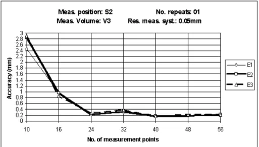
Number of measurement points: the number of measurement points adopted as a standard was 32 points. For the S2 measurement region with volume V2, the number of points varied in 10, 16, 24, 32, 40, 48 and 56 points. The points were distributed along the height of the parallelepiped, on its surface, in 4 equidistant layers, distributed as uniformly as possible.
Figure 6show s t he end- effect or accuracy calculat ed as t he average of t he offset absolut e values bet w een t he sim ulat ed end- effect or posit ion and t he expect ed posit ion ( nom inal) , using t he t hree m easurem ent regions, S1, S2, S3, evaluat ed in each of t he evaluat ion regions, E1, E2, E3. As it w as expect ed t he robot achieved a bet t er accuracy on t he evaluat ion region closer t o t he correspondent m easurem ent region.
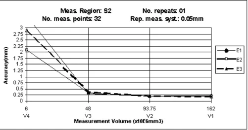
Figure 7 show s t he variat ion of t he end- effect or accuracy in each evaluat ion region as a funct ion of t he m easurem ent volum e in t he front region of t he workspace. I t is evident t hat a relat ively sm all m easur em ent volum e can induce param et er dependencies hindering an effect ive calibrat ion. This can be realized by observing t he condit ion num ber of t he Jacobian m at rix ( eq.29 ) .
Volum e 3 w as adopt ed t hen as a st andard for t he m easurem ent volum e. This w as due t o t he r em nant m argin for accuracy im provem ent show ed in Fig. 7 for t his volum e, as a funct ion of ot her variables ( t he condit ion num ber can be reduced) ot her t han t he m easurem ent volum e.
For a verificat ion of t he influence of evaluat ion volum es on t he end- effect or accuracy wit h large m easurem ent volum es, m easurem ent and evaluat ion regions and volum es were changed in t he graphic of Fig. 11. The result s show t hat t here is an expect ed accuracy im provem ent w hen t he evaluat ion volum e shrinks.
Conclusions
Aim ing at t he feasibilit y and reliabilit y of an opt im um robot calibrat ion design a syst em at ic m et hodology w as present ed based on opt im izat ion of t he m at hem at ical m odel for param et er ident ificat ion and on t echniques for com put er sim ulat ion of t he act ual calibrat ion st ages. An im provem ent on t he robot end- effect or accuracy w as evident w hen t he opt im ized m odel- param et er ident ificat ion w as used, elim inat ing num erical deficiencies caused by redundant param et ers. The opt im ized m odel- param et er values proved t o aid t he ident ificat ion t ow ards a bet t er act ual kinem at ic m odel. The act ual robot sim ulat ion w as perform ed by int roducing random errors int o t he nom inal kinem at ic m odel t o represent t he act ual j oint encoder offset s. Joint r andom errors in t he m at hem at ical m odel w ere chosen t o be a proper st at ist ical represent at ion of t he act ual robot j oint errors and relat ed t o t he m easured repeat abilit y. The m easurem ent syst em w as sim ulat ed using r andom errors sim ilar t o t hose obt ained from specific experim ent at ion or fr om t he repeat abilit y report ed by t he m anufact urer. The proposed m et hodology allows t he est ablishm ent of bet t er m easurem ent areas ( or volum es) and planning of m easurem ent procedures, wit h evident advant ages on t he calibrat ion result s.
References
Bazergui, A., Goldenberg, A. A. and Apkarian, J., 1984, " An Exact Kinem at ic Model of PUMA 600 Manipulat or" , I EEE Transact ions on Syst em s, Man, and Cybernet ics, SMC- 14, No. 3, pp. 483- 7. [ Links]
Baker, D.R., 1990, " Som e t opological problem s in robot ics" , The Mat hem at ical I nt elligencer,Vol.12, No.1, pp. 66-76. [ Links]
Bernhardt , R., 1997, " Approaches for com m issioning t im e reduct ion" , I ndust rial Robot , Vol. 24, No. 1, pp. 62-71. [ Links]
Dennis, J.E. and Schnabel, R.B., 1983, " Num erical Met hods for Unconst rained Opt im izat ion and Nonlinear Equat ions" , 1st ed. Prent ice- Hall, New Jersey, USA. [ Links]
Driels, M.R. and Pat hre, U.S. ( 1990) " Significance of Observat ion St rat egy on t he Design of Robot Calibrat ion Experim ent s" , Journal of Robot ic Syst em s, Vol. 7, No. 2, pp. 197- 223. [ Links]
Driels, M.R., Sw ayze, Lt W. USN and Pot t er, Lt S. USN, 1993, " Full- Pose Calibrat ion of a Robot Manipulat or Using a Coordinat e- Measuring Machine" , The I nt ernat ional Journal of Advanced Manufact uring Technology, Vol. 8, pp. 34- 41. [ Links]
Everet t , L.J. and Whit ney. D.F., 1987, " A Met hod for I nverse Robot Calibrat ion" , Transact ions of t he ASME, No. 109, pp. 36- 43. [ Links]
Everet t , L.J. and Hsu, T- W, 1988, " The Theory of Kinem at ic Param et er I dent ificat ion for I ndust rial Robot s" , Transact ion of ASME, No. 110, pp. 96- 100. [ Links]
Everet t , L.J., ( 1993) , " Research t opics in robot calibrat ion" , Robot Calibrat ion, edit ed by R. Bernhardt and S. L. Albright , Chapm an & Hall, London. [ Links]
Got t lieb, D.H., 1986, " Robot s and Topology" , Proceedings of t he I EEE I nt ernat ional Conference on Robot ics and Aut om at ion, pp. 1689- 1691. [ Links]
Hidalgo, F and Brunn, P, ( 1998) , " Robot Met rology and Calibrat ion Syst em s - a m ar ket review" , I ndust rial Robot , Vol. 25, No. 1, pp. 42- 47. [ Links]
Jiang, B. C.; Black, J.T. and Duraisam y, R. " A Review of Recent Developm ent s in Robot Met rology" , Journal of Manufact uring Syst em s, Vol. 7, No. 4, ( 1988) , 339- 357. [ Links]
Law son, C. L. and Hanson, R.J., 1974, " Solving Least Squares Problem s" , Prent ice- Hall, New Jersey, USA. [ Links]
McKerrow , P. J., 1995, " I nt roduct ion t o Robot ics" , 1sted. Addison Wesley Print ing Group. [ Links] Mooring, B.W. and Pack, T.J., 1986, " Det erm inat ion and Specificat ion of Robot Repeat abilit y" , Proceedings of 1986 I EEE I nt ernat ional Conference on Robot ics and Aut om at ion, pp. 1017- 1023. [ Links]
Mot t a, J. M. and McMast er, R. S. " I m proving Robot Calibrat ion Result s Using Modeling Opt im isat ion" , Proceedings of t he 1997 I EEE I nt ernat ional Sym posium of I ndust rial Elect ronics" , Guim araes, Port ugal, pp.
SS291-296. [ Links]
Ow ens, J., 1994, " Robot rak: Calibrat ion on a Shoest ring" , I ndust rial Robot , Vol. 21, No. 6, pp. 10-13. [ Links]
Paul, R. P., 1981, " Robot Manipulat ors - Mat hem at ics, Program m ing, and Cont rol" , MI T Press, Bost on, USA. [ Links]
Preising, B., Hsia, T.C., 1995, " Robot Perform ance Measurem ent and Calibrat ion Using a 3D Com put er Vision Syst em " , Robot ica, Vol. 13, pp. 327- 37. [ Links]
Press, W.H., Teukolsky, S.A., Flannery, B. P. and Vet t erling, W.T., 1994, " Num erical Recipes in Pascal- The Art of Scient ific Com put er" , 1sted. Cam bridge Universit y Press, New York, USA. [ Links]
Rot h, Z.S., Mooring, B.W. and Ravani, B., 1987, " An Overview of Robot Calibrat ion" , I EEE Journal of Robot ics and Aut om at ion, RA- 3, No. 3, pp. 377- 85. [ Links]
Schroer, K., 1993, " Theory of kinem at ic m odeling and num erical procedures for robot calibrat ion" , Robot Calibrat ion, edit ed by R. Bernhardt and S. L. Albright , Chapm an & Hall, London. [ Links]
Schroer, K., Albright , S. L. and Gret hlein, M., 1997, " Com plet e, Minim al and Model- Cont inuous Kinem at ic Models for Robot Calibrat ion" , Robot ics & Com put er- I nt egrat ed Manufact uring, Vol. 13, No. 1, pp. 73- 85. [ Links] Whit ney, D. E., Lozinski, C.A. and Rourke, J.M., 1986, " I ndust rial Robot Forward Calibrat ion Met hod and Result s" , Journal of Dynam ic Syst em s, Measurem ent , and Cont rol, No. 108, pp. 1- 8. [ Links]
Zhuang, H., 1992, " A Com plet e and Param et rically Cont inuous Kinem at ic Model for Robot Manipulat ors" , I EEE Transact ions on Robot ics and Aut om at ion, Vol. 8, no. 4, pp. 451- 63. [ Links]
Manuscript received: April 1998; revision received: March 1999. Technical Edit or: Paulo Eigi Miyagi.
All the content of the journal, except w here otherw ise noted, is licensed under a Creative Com m ons License
A B CM
Av. Rio Branco, 1 2 4 - 1 4 . Andar 2 0 0 4 0 - 0 0 1 Rio de Janeiro RJ - Brazil
Tel. : ( 5 5 2 1 ) 2 2 2 1 - 0 4 3 8 Fax.: ( 5 5 2 1 ) 2 5 0 9 -7 1 2 8