UNIVERSIDADE DE LISBOA FACULDADE DE CIÊNCIAS DEPARTAMENTO DE INFORMÁTICA
CONFIDENTIALITY, INTEGRITY AND NON-REPUDIATION
IN SMARTGRIDS
Paulo Miguel Santos Moniz
MESTRADO EM SEGURANÇA INFORMÁTICA
UNIVERSIDADE DE LISBOA FACULDADE DE CIÊNCIAS DEPARTAMENTO DE INFORMÁTICA
CONFIDENTIALITY, INTEGRITY AND NON-REPUDIATION
IN SMARTGRIDS
Paulo Miguel Santos Moniz
Orientador
Alysson Neves Bessani
MESTRADO EM SEGURANÇA INFORMÁTICA
Resumo
No actual contexto macroeconómico mundial é essencial a adopção de novas formas de geração de energia, alternativas à utilização de recursos fósseis, combinada com os objectivos de fiabi-lidade e quafiabi-lidade dos fornecimentos e de indução de competitividade nos mercados. Torna-se necessário produzir, transportar e distribuir energia de forma sustentável sem prejudicar o ecossis-tema. A visão de uma infraestrutura com maior controlo, onde redes, produtores e consumidores têm papeis significativamente mais activos, está a provocar uma mudança de paradigma nas redes eléctricas e na sua gestão que se materializa no conceito das Smart Grids.
Para obter um elevado nível de controlo de operação da rede, necessário para a concretização das funcionalidades prometidas pelas Smart Grids, a arquitectura terá que evoluir de modo a comportar um maior número de unidades remotas inteligentes, o desenvolvimento de novos sistemas técnicos e comerciais, o aumento de trocas de mensagens entre aplicações e a interligações entre diver-sas redes. Esta complexidade é bastante maior daquela que poderemos encontrar nas actuais infra-estruturas de sistemas de informação para a transmissão e distribuição de energia eléctrica e apresenta novos desafios no que diz respeito à disponibilidade da rede e, em particular, à sua segurança. Os novos equipamentos, aplicações, hardware, protocolos de comunicação, operação e administração da rede vão introduzir novas potenciais vulnerabilidades que podem ser explora-das por indivíduos mal intencionados ou simplesmente por erros de operação. Esta preocupação acerca da disponibilidade e segurança da rede de energia eléctrica do futuro evidenciam a impor-tância que assumem a segurança e disponibilidade da infra-estrutura dos sistemas de informação e comunicações que a suportam.
Este trabalho propõem-se analisar a confiabilidade das Smart Grids no que diz respeito aos seus aspectos de segurança de tecnologias de informação, incidindo em particular no projecto Portu-guês de Smart Grid denominado InovGrid. Este projecto de investigação irá descrever as funcio-nalidades da arquitectura InovGrid fazendo uma análise detalhada dos vectores de ataque e os riscos eminentes associados à sua implementação. Este estudo irá avaliar e propor soluções no domínio da autenticidade, confidencialidade e não-repudiação de informação numa arquitectura peculiar e heterogenia com a das Smart Grids.
Abstract
In the current global macroeconomic context is essential to adopt new ways of generating energy alternatives to fossil fuels, combined with the objectives of reliability and quality of delivery and induction of competitiveness in markets. It is necessary to produce, transport and distribute energy in a sustainable way without harming the ecosystem. The vision of an infrastructure with more control, where networks, producers and consumers have significantly more active roles, is causing a paradigm shift in electricity networks and their operations that is embodied in the concept of Smart Grids.
To obtain a high level of control required to achieve the new features promised by Smart Grids, the architecture will need to comprise more intelligent remote terminal units, the development of new technical and commercial systems, the increase of the number of messages exchange bet-ween applications and also interconnections betbet-ween enterprise networks. This complexity, far higher than found in present transmission and distribution infrastructures, will bring several chal-lenges considering network reliability and security in particular. All the new devices, applications, hardware, communication protocols, network operations and administration will introduce potential vulnerabilities that might be explored by malicious users or simple by erroneous actions from a va-riety of external and internal sources. This concern about security and reliability of the future power grids increase the importance of the information technology and communications infrastructures and their security.
This work proposes to analyze Smart Grid’s reliability regarding its information technology security but focusing the study in the Portuguese Smart Grid project implementation, named as InovGrid. It will describe the functionalities of the InovGrid architecture providing a detailed analysis of its at-tack vectors and the eminent risks associated with the implementation. It will propose and analysis solutions for confidentiality, authenticity and non-repudiation aspects in such peculiar and hetero-geneous networks.
Acknowledgments
Firstly I would like to thank Luis Barruncho from Logica and Vergilio Rocha from EDP that encoura-ged me and allow me to apply in this Master and also gave me all the necessary support throughout this period to reach this stage of completion. They were the main responsible for this adventure and deserve these special words to show my appreciation.
I would also like to thank Professor Paulo Verissimo by the captivating and engaging way that he presents the information security challenge in today’s society. He has motivated me and led me to change the course of my career.
Also a special appreciation words to Miguel Areias, Carlos Mota Pinto and Aurélio Blanquet, from EDP, that made possible the work presented in this thesis. They are part of the EDP’s group that leads the implementation of the Portuguese Smart Grid project and they have shown, since the beginning, interest and support on my thesis proposal. Without their help this work would not be possible.
To Alysson, whose guidance was essential during the development of this work, especially by give me interesting ideas and also being very supportive in this endeavor.
To Gabriela and André for their patience and support that help me to complete this program. Finally I would like to thank to my MSIT-IS colleagues and friends for their spirit of companionship, support, patience and, above all, good humor throughout all this Master.
Contents
1 Introduction 1
1.1 Motivation . . . 1
1.2 Contribution . . . 2
1.3 Document Organization . . . 2
2 Smart Grids Security Challenges 3 2.1 Smart Grid Concept . . . 3
2.2 Smart Grid Security Risks and Strategy . . . 5
2.3 Smart Grids Security Requirements . . . 6
2.3.1 Access Control . . . 7
2.3.2 Identification and Authentication . . . 8
2.3.3 Audit and Accountability . . . 8
2.3.4 Configuration Management . . . 10
2.3.5 Physical and Environmental Security . . . 10
2.3.6 Security Incident Management . . . 10
2.3.7 Information Systems Acquisition, Development and Maintenance . . . 11
2.4 Cryptography and Key Management . . . 11
2.4.1 Computational Issues . . . 12 2.4.2 Communications Issues . . . 12 2.4.3 General Issues . . . 12 3 InovGrid Project 14 3.1 Architecture Description . . . 14 3.1.1 Information Systems . . . 15
3.1.3 Energy Box . . . 17
3.1.3.1 Communications Module . . . 19
3.1.3.2 Metering Module . . . 20
3.1.4 Home Area Network . . . 20
3.1.5 Local Area Network . . . 20
3.1.6 Wide Area Network . . . 21
3.2 InovGrid Functional Requirements . . . 21
3.2.1 Information Systems Requirements . . . 21
3.2.2 Distribution Transformer Controller (DTC) Functional Requirements . . . 25
3.2.3 Energy Box Functional Requirements . . . 30
4 InovGrid Security Analysis 35 4.1 Security Analysis Methodology . . . 35
4.1.1 Planning and Collecting System Information . . . 36
4.1.2 System Decomposing . . . 36
4.1.3 Identify Vulnerabilities (STRIDE approach) . . . 36
4.1.4 Build Attack Tree . . . 37
4.1.5 Rank Vulnerabilities . . . 37
4.2 Data Flow Analysis and Attack Modeling . . . 38
4.2.1 Information Systems - Data Flow Analysis and Attack Modeling . . . 38
4.2.1.1 Data Flow 2-1 - Collect and process power measure information. . . 38
4.2.1.2 Data Flow 13-2 - Send configuration parameters for energy boxes and distribution transformer controllers. . . 40
4.2.1.3 Data Flow 12-2 - Send information to control public lighting. . . 41
4.2.1.4 Data Flow 10-2 - Send information to control power supply. . . 42
4.2.1.5 Data Flow 9-2 - Send information to regulate contracted power. . . . 43
4.2.1.6 Data Flow 8-2 - Send rate information. . . 45
4.2.1.7 Data Flow 11-2 - Send firmware update. . . 45
4.2.1.8 Data Flow 19-2 - Send information to customer. . . 47
4.2.1.9 Data Flow 2-15 - Acquiring grid status information. . . 47
4.2.1.10 Data Flows for user interfaces 14 and 18 - Information systems users interface. . . 48 4.2.2 Distribution Transformer Controller - Data Flow Analysis and Attack Modeling 49
4.2.2.1 Data Flow 1-2 - Record date and time of maximum power by rate type. 50
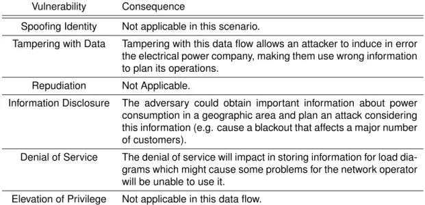
4.2.2.2 Data Flow 1-3 - Record load diagram of power. . . 51
4.2.2.3 Data Flow 1-4 - Record load diagram of public lighting power. . . 51
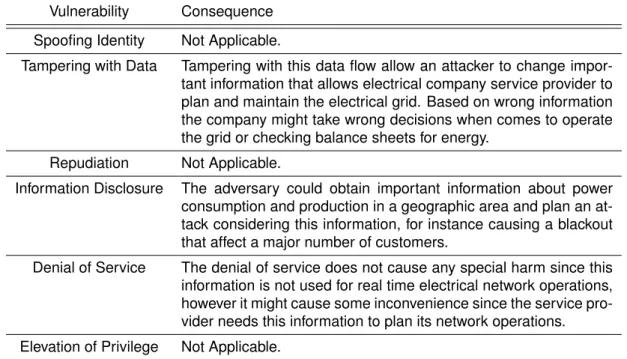
4.2.2.4 Data Flow 1-5 - Record figures for consumption and production. . . 52
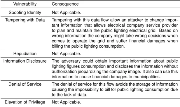
4.2.2.5 Data Flow 1-6 - Record figures for public lighting consumption. . . . 53
4.2.2.6 Data Flow 1-7 - Record quality of service. . . 54
4.2.2.7 Data Flow 23-8 - Store information from energy boxes. . . 55
4.2.2.8 Data Flow 11-10-16 - Control Public lighting timetable, connection and disconnection. . . 56
4.2.2.9 Data Flow 11-10-14 - Control distribution transformer controller func-tions. . . 58
4.2.2.10 Data Flow 11-10-12 - Control circuit breaker transformers. . . 59
4.2.2.11 Data Flow 25-23 - Costumers without electricity supply. . . 60
4.2.2.12 Data Flow 24-25-11 - Monitor low voltage bus value. . . 61
4.2.2.13 Data Flow 26-25-11 - Sending alarms for imbalance or overload phases. . . 61
4.2.2.14 Data Flow 11-19 - Firmware update. . . 62
4.2.2.15 Data Flow 17-18 - Store events . . . 64
4.2.2.16 Data Flow 11-22-15 - Connect and disconnect independent circuits 65 4.2.2.17 Data Flow 13-22-11 - Identifying default currents between phases . 66 4.2.2.18 Data Flow 11-9-23 - Adjust Clock . . . 66
4.2.2.19 Data Flow 21-20 - Interface with user . . . 67
4.2.2.20 Data Flow 11-23 - Data from information systems to energy box. . . 68
4.2.3 Energy Box - Data Flow Analysis and Attack Modeling . . . 69
4.2.3.1 Data Flow 1-2 - Storing maximum power . . . 70
4.2.3.2 Data Flow 1-3 - Figures for consumption and production . . . 71
4.2.3.3 Data Flow 1-4 - Quality of service information . . . 72
4.2.3.4 Data Flow 1-5 - Billing information . . . 73
4.2.3.5 Data Flow 1-10-18 - Send power meter information . . . 74
4.2.3.6 Data Flow 18-12-9 - Firmware update . . . 76
4.2.3.7 Data Flow 18-11-8 - Technical management . . . 77
4.2.3.9 Data Flow 16-17 - Store events . . . 79
4.2.3.10 Data Flow 18-6-7 - Customer information . . . 79
4.2.3.11 Data Flows 19-11, 19-12, 19-14 - Interface with user . . . 80
4.3 Risk Understanding . . . 81
5 Security Architecture for InovGrid 83 5.1 Objectives . . . 83
5.1.1 Authentication and Non-Repudiation . . . 83
5.1.2 Device Attestation . . . 84
5.1.3 Confidentiality . . . 84
5.2 Basic Tools . . . 85
5.2.1 Public Key Cryptography . . . 85
5.2.2 Public Key Certificates . . . 86
5.2.3 Trusted Computing . . . 86
5.3 Public Key Infrastructure . . . 88
5.3.1 Public Key Infrastructure Framework . . . 88
5.3.1.1 Trusted Models in a PKI . . . 89
5.3.1.2 Public Key Infrastructure logical components . . . 89
5.3.1.3 Certificates Validation and Revocation . . . 91
5.3.2 Public Key Infrastructure in InovGrid . . . 91
5.3.2.1 Trust Model . . . 92
5.3.2.2 Certificate Validation . . . 92
5.3.2.3 Certificate Revocation . . . 93
5.4 Security Operations . . . 93
5.4.1 Overall Security Architecture . . . 93
5.4.2 Assumptions . . . 95
5.4.3 Certificates Operational Procedures . . . 95
5.4.3.1 Obtaining a InovGrid Certificate . . . 95
5.4.3.2 Certificate Validation . . . 96
5.4.4 Confidentiality . . . 97
5.4.5 Authentication and Non-Repudiation . . . 98
5.4.6 Remote Device Attestation . . . 99
6 Conclusion 102
6.1 Conclusion . . . 102 6.2 Future Work . . . 103
List of Figures
2.1 Smart Grid overall picture. Source: NIST Framework and Roadmap for Smart Grid
Interoperability Standards, Release 1.0 (NIST SP 1108). . . 4
3.1 InovGrid Global Architecture . . . 15
3.2 Energy Box Architecture . . . 19
4.1 Information Systems Data Flow . . . 38
4.2 Distribution Transformer Controller Data Flow Analysis . . . 50
4.3 Energy Box Data Flow Analysis . . . 70
5.1 Remote Attestation Process . . . 88
5.2 PKI Trust Model for InovGrid . . . 92
5.3 InovGrid Security Architecture . . . 94
5.4 Obtaining a InovGrid Certificate . . . 96
5.5 Obtain an OCSP Assertion . . . 97
5.6 Generating a Shared Key Using Signed Diffie-Hellman Algorithm . . . 98
5.7 One Way Authentication Messages . . . 99
5.8 Two Way Authentication Messages . . . 99
List of Tables
3.1 Power Meter Requirements . . . 22
3.2 Storage Information Requirements . . . 23
3.3 Remote Parameterization Requirements . . . 24
3.4 Interface with the Consumer Requirements . . . 24
3.5 Quality of Service Requirements . . . 24
3.6 Technical Management Requirements . . . 25
3.7 Commercial Management Requirements . . . 25
3.8 Power Meter Requirements . . . 26
3.9 Storage Information Requirements . . . 26
3.10 Remote Commands and Parameterization Requirements . . . 27
3.11 Quality of Service Requirements . . . 27
3.12 Firmware Update Requirements . . . 28
3.13 Technical Management Requirements . . . 28
3.14 Remote Control, Defect Detection and Automation Requirements . . . 28
3.15 Interface with the User Requirements . . . 28
3.16 Record of Events Requirements . . . 29
3.17 Clock Requirements . . . 29
3.18 Hourly Breakdown Requirements . . . 30
3.19 Power Meter Requirements . . . 30
3.20 Storage Information Requirements . . . 31
3.21 Parameterization and Remote Meter Actuation Requirements . . . 32
3.22 Interface with the Consumer Requirements . . . 32
3.23 Quality of Service Requirements . . . 33
3.25 Technical Management Requirements . . . 33
3.26 Events Requirements . . . 34
3.27 Clock Requirements . . . 34
4.1 STRIDE Analysis for Data-Flow 2-1 . . . 39
4.2 STRIDE Analysis for Data-Flow 13-2 . . . 41
4.3 STRIDE Analysis for Data-Flow 12-2 . . . 42
4.4 STRIDE Analysis for Data-Flow 10-2 . . . 43
4.5 STRIDE Analysis for Data-Flow 9-2 . . . 44
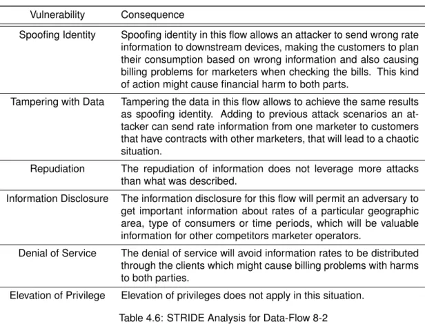
4.6 STRIDE Analysis for Data-Flow 8-2 . . . 45
4.7 STRIDE Analysis for Data-Flow 11-2 . . . 46
4.8 STRIDE Analysis for Data-Flow 19-2 . . . 47
4.9 STRIDE Analysis for Data-Flow 2-15 . . . 48
4.10 STRIDE Analysis for user interfaces Data-Flows . . . 49
4.11 STRIDE Analysis for Data-Flow 1-2 . . . 50
4.12 STRIDE Analysis for Data-Flow 1-3 . . . 51
4.13 STRIDE Analysis for Data-Flow 1-4 . . . 52
4.14 STRIDE Analysis for Data-Flow 1-5 . . . 53
4.15 STRIDE Analysis for Data-Flow 1-6 . . . 54
4.16 STRIDE Analysis for Data-Flow 1-7 . . . 55
4.17 STRIDE Analysis for Data-Flow 23-8 . . . 56
4.18 STRIDE Analysis for Data-Flow 11-10-16 . . . 57
4.19 STRIDE Analysis for Data-Flow 11-10-14 . . . 58
4.20 STRIDE Analysis for Data-Flow 11-10-12 . . . 59
4.21 STRIDE Analysis for Data-Flow 25-23 . . . 60
4.22 STRIDE Analysis for Data-Flow 24-25-11 . . . 61
4.23 STRIDE Analysis for Data-Flow 26-25-11 . . . 62
4.24 STRIDE Analysis for Data-Flow 11-19 . . . 63
4.25 STRIDE Analysis for Data-Flow 17-18 . . . 64
4.26 STRIDE Analysis for Data-Flow 11-22-15 . . . 65
4.27 STRIDE Analysis for Data-Flow 13-22-11 . . . 66
4.29 STRIDE Analysis for Data-Flow 21-20 . . . 68
4.30 STRIDE Analysis for Data-Flow 11-23 . . . 69
4.31 STRIDE Analysis for Data-Flow 1-2 . . . 71
4.32 STRIDE Analysis for Data-Flow 1-3 . . . 72
4.33 STRIDE Analysis for Data-Flow 1-4 . . . 73
4.34 STRIDE Analysis for Data-Flow 1-5 . . . 74
4.35 STRIDE Analysis for Data-Flow 1-10-18 . . . 75
4.36 STRIDE Analysis for Data-Flow 18-12-9 . . . 76
4.37 STRIDE Analysis for Data-Flow 18-11-8 . . . 77
4.38 STRIDE Analysis for Data-Flow 18-14-13 . . . 78
4.39 STRIDE Analysis for Data-Flow 16-17 . . . 79
4.40 STRIDE Analysis for Data-Flow 18-6-7 . . . 80
Chapter 1
Introduction
1.1
Motivation
Energy is one of the biggest challenges that humanity faces in the future. Societies aim to transform the current energy system into one which will be more sustainable that does not hurt the environ-ment and the ecosystems. Efficient transmission and distribution of electricity is a fundaenviron-mental requirement for providing societies and economies with essential energy resources. The common vision that electrical companies are moving toward should meet the needs of the future energy objectives for sustainability, security and competitiveness. Electrical grids are currently enduring a new and fundamental evolution, materialized in the vision of the smart grid concept [1]. Smart grid should be flexible and accessible granting connection access to all network users, particularly for renewable power sources and high efficiency local generation with zero or low carbon emission. Nowadays distribution service management and power grid operation are supported by a complex architecture of actuators, sensors, communications and information systems, assuring extensive collection and management of real-time data, run-time decision-support and coordinated control. This constitutes the core of modern supervisory control and data acquisition (SCADA) systems, as well as advanced metering infrastructures (AMI), which implement process oriented and integrated approaches both to grid and to client management, more efficient control paradigms, improve plant and staff safety, and reduce the cost of operation.
The use of standard hardware and software in SCADA systems combined with improved communi-cation protocols and interconnectivity to outside networks, both corporate and the internet, allow to cope with increasing complexity of networks and service and provide high levels of efficiency and effectiveness in decision support to operation and operations planning. Furthermore, new business and market drivers promote the deployment of large numbers of AMI related intelligent devices down to the customer’s premises, with bi-directional wired or wireless communication and capabili-ties for data collection, storage, concentration and distribution as well as command execution. Nevertheless all the evolutions in the SCADA systems and related infrastructures the smart grids will dramatically change the way electrical power networks are managed. The active networks of the future will efficiently link small and medium scale power sources enabling efficient decisions on
how to best operate the network. The level of control required to achieve such operations are far higher than found in present transmission and distribution systems as so the number of intelligent remote terminal units spreading over the entire network. Smart Grids will enforce the need for systems to communicate among themselves also to satisfy new functionalities and services to customers, increasing this way the importance of the information technology and communications infrastructures.
While information technologies are essential to achieve the benefits of smart grid for the customers and society, they also introduce more complexity, new interdependencies and vulnerabilities that could be explored by malicious individuals or simple by misuse of information systems [2]. Ap-proaches to secure these new critical infrastructures must be designed and implemented early in order to assure the grid reliability and resilience in the context of increased number of sensors, decentralized processing and holistic enterprise data management.
1.2
Contribution
This research project is part of the major efforts that we are assisting today to provide security for new cyber infrastructures that will support the context of the new generation of power grids. This thesis provides an analysis of the potential problems and security requirements regarding generic architecture for smart grids but will focus the study in the Portuguese case of smart grid implementation project, leaded by EDP, henceforth identified as InovGrid.
Therefore this work will analyze the InovGrid architecture identifying potential attack vectors and provides an overall risk analysis for the current project implementation. Latter will focus the study in specific security problems of the smart grid related with integrity, authentication and non-repudiation of commercial and technical information through the network.
1.3
Document Organization
The document is organized to give a structured approach and frame for the specific problem in the context of the smart grids environment. We believe that the structure adopted will give a better understanding for the contribution of this work to the overall picture of the smart grids. In Chap-ter 2 is presented a general overview of the smart grid concepts and challenges that includes the risks associated to this new paradigm, the security requirements for these new infrastructures and cryptography and key management issues. In Chapter 3 we introduce the Portuguese smart grid implementation, named as InovGrid project, describing the overall architecture and also the functional requirements. In Chapter 4 we make a security analysis, identifying the attack vectors for specific vulnerabilities and we present some risk awareness considerations. In Chapter 5 we present a security architecture for the InovGrid to mitigate all the security vulnerabilities identified in chapter 4. Finally in Chapter 6 we draw some conclusions and point some venues for future work.
Chapter 2
Smart Grids Security Challenges
This Chapter give an overview of the smart grid concept, presenting high level actors and interac-tions. It will enumerate all the principles behind smart grid philosophy, focusing in the networking reliability and information security. It also explain the security strategy that should guide the im-plementation of those networks in order to provide reliability. Furthermore we describe security requirements to enforce the security strategy as also the issues concerning with their implementa-tion in such grid’s architecture.
2.1
Smart Grid Concept
Smart grid is envisioned to transform the current power transport and distribution network to one more intelligent, with a high level of control and more efficient operations. To fulfill these goals the smart grid will take advantage of all available technologies from applications and hardware components to communication protocols and network sensors. In detail a smart grid will facilitate the following seven principles [3]:
• more autonomous control of the network in order to facilitate resiliency against component failures and natural disasters usually identified as self-healing capabilities;
• pursuing the global energy sustainability objective since smart grid will comprise renewable resources like wind and solar energy, either from consumers to power plants;
• two-way communication between the consumer and utility. In the new smart grid paradigm
consumers can have an active role as they can tailor their energy consumption based on preferences and information that they could access (price, profile consume, etc.). They also can play the role of micro producers selling energy to the network operators;
• improved market efficiency by creating new services and functionalities made available to consumers and other market participants;
• higher quality of service for the 21st century needs (free of voltage sags and spikes as well as other disturbances and interruptions).
• improve infrastructure resiliency against malicious attacks and misuse operations from inter-nal and exterinter-nal sources through better cybersecurity and physical security mechanisms.
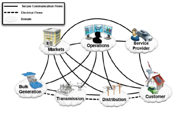
The following figure depicts the overall picture of smart grid’s actors and interactions. This picture identifies seven domains where each needs to transmit, store, edit and process information.
Figure 2.1: Smart Grid overall picture. Source: NIST Framework and Roadmap for Smart Grid
Interoperability Standards, Release 1.0 (NIST SP 1108).
In the picture above actors are systems, devices or programs that make decisions and exchange information necessary for executing applications within the smart grid and the continuous lines represent the interconnections between those actor’s domains that would be implemented in a myriad of different communication’s technologies.
Smart grid will introduce thousands of new components to the electric infrastructure but it also comprises different systems and applications with different proposes and requirements. Many of those components, systems and applications are critical to interoperability and reliability of the network and they will need to communicate bidirectional maintaining confidentiality, integrity, and availability.
2.2
Smart Grid Security Risks and Strategy
Security in the context of the smart grids should cover all the issues involving the automation and communications that affect the operation of the network as also all the business processes that support the service being delivered to customers. Saying that it means we are considering all the systems and applications that enables all the automation processes as also organization proce-dures like assets inventory, patch updates or firewall management. Currently, critycal infrastruc-ture’s operators also have wide spread concerns regarding security however smart grids brings brand new risks and vulnerabilities [4] to operations especialy due to the following situations:
• The amount of data being managed will be much more than we handle in today’s critical infrastructures. There are some approaches that even consider the use of the cloud to provide storage space [5]. This fact leverage data privacy problems since great part of the collected information will be related with customers.
• Smart grids will increase the complexity of information system’s architectures, leading to more vulnerable points and leveraging the possibility of failures resulting from bad operations.
• Since the number of intelligent sensors, systems, applications and even third parties involved
in network operations will increase dramatically, we will have a large number of stakeholders which will be difficult to control when comes to ensuring security requirements in the services they provide, whenever these are applications development or communications infrastruc-tures.
• Since the architecture spreads from the customer home to the biggest electrical power
pro-ducers, assuming a big geographic dispersion, we will have to consider different communi-cations techniques and protocols, sometimes solutions compromised by local conditions like poor terminal equipments with limited possibilities to implement security mechanisms.
• Increasing vulnerabilities resulting from the increase number of softwares and firmwares.
• The number of physical installations that will maintain equipments connected to the
commu-nication network will also increase, which means that the network access control will also be more difficult to implement.
• The use of new technologies can introduce new vulnerabilities which is common before the technologies become mature.
• Interconnected networks will also be a reality which also leads to more common
vulnerabili-ties. As an example we can have network interconnections inside the same company, since the new functionalities leveraged by smart grids will force more interactions between commer-cial and technical systems that, most of times, are at separated networks.
• The systems that controls critical infrastructures have real time requirements that could be jeopardized in such complex architecture like the ones brought by smart grids.
Smart grid security strategy should address prevention, detection, response and recovery based on a defense-in-depth approach [6]. It means that the security should be implemented in all archi-tecture layers with one or more security mechanism at each layer since no single security measure can counter all type of threats. This way the risk of one component being compromised is mitigated with additional security mechanisms. As an example we might have a system comprising intrusion detection systems (IDS), firewalls, incident response operation and antivirus. Saying that the stra-tegy should address prevention, detection, response and recovery means that security should be planned from the design phase, for instance at application’s design and development, to infrastruc-ture operations, by implementing a security operation center with incident response capabilities, through recovery using intrusion tolerant architectures [7] or detection provided by intrusion detec-tion systems.
In cyber security strategy for smart grids is also important to assume that the logical security archi-tecture should be an iterative process that should revising the archiarchi-tecture to address new threats, vulnerabilities, and technologies and that all systems will be targets for an attack or misuse. It is also necessary to balance the impact of a security breach and the resources required to implement mitigating security measures since some of the solutions might jeopardize the system functiona-lities and related services or simple too expensive to be implemented. Nevertheless, and since each smart grid implementation will be a different case, we should identify the high level security requirements.
2.3
Smart Grids Security Requirements
This section intent to identify and describe the challenges to implement typical high level security requirements for a typical smart grid architecture. These security requirements are accepted to be essential to adopt a depth defense strategy for a smart grid implementation and are selected considering the security constrains of the power systems operations that imposes strictly require-ments for systems availability and resilience. In practice it means that, when in presence of a cyber attack, the systems should, ideally, resist without affecting the operation or, at least, recovery fast and gracefully.
In last years IT security has become a major concern in the organizations and we have witnessed the development of many cyber security solutions to protect IT corporate networks and to reduce their vulnerability to cyber attacks. It is common in corporate networks to have security mechanisms that goes from firewalls to intrusion detection systems, through virtual private networks. This type of solutions have proven to be quite effective in securing corporate IT infrastructures, however critical infrastructures impose different requirements [8] and consequently different solutions that we may resume as:
• In corporate networks main concerns are about protecting data integrity, confidentiality and
availability. In power grid it is also important to maintain these security properties however the main motivation is to protect human’s safety, normal network operations, network equipment and power lines.
• In corporate networks the architecture is more centralized because data resides at central servers where is required more protection than the edge nodes which are used by end users, whereas in critical infrastructures we have intelligent remote devices at the edges that controls electrical power equipments like circuit breaker or re-closers. The incorrect operation of these devices can do harm to human life or affect the service provided to the customers. Therefore, in power grid networks, most notably in smart grids, the edge nodes need the same level of protection as central devices.
• Operating systems and communications also differ from corporate networks to electrical po-wer critical information infrastructures. In the former we find Windows, Unix and Linux as operating systems and Ethernet is used to connect all devices with IP-based protocols. In critical information infrastructures we also find in field devices vendor proprietary operating systems and many different communications protocols (e.g. IEC61850 [9], DNP 3.0 [10]). Therefore, common security solutions designed for corporate networks might be ineffective for critical information infrastructures.
• In corporate networks some practices to solve problems in case of failure might pass from rebooting a machine or application and also the delay in communications are allowed since, besides systems that support online market transactions, most applications are not real time, whereas in critical information infrastructures these behaviors or properties are not accep-table.
The requirements described in next sections are equivalent to others presented in well known fra-meworks like ISO 27002 [11], however the intention for the current work is to enhance the issues regarding their implementation in smart grid’s context. Therefore, while describing the require-ments, we do not intent to provide technical solutions or technologies for their implementation and some might apply to specific architecture elements or all components, while others are strictly pro-cedural or organizational. The requirements should be implemented in the field regarding a specific security strategy in each smart grid implementation case, which should led to the right choice of technical solutions and technologies.
2.3.1
Access Control
Access control is a big challenge in smart grids security due to the myriad of different components, systems, stakeholders and locations. A well defined access control should start by defining access control policies to grant the right resources are accessed only by the appropriate individuals. Ac-cess control comprises network acAc-cess, wireless acAc-cess, remote acAc-cess, mobile devices acAc-cess and account management. The philosophy beyond the security access policy should be based on separation of duties and least privilege rationale [12].
However access control in not only to define policies but also about to monitor access activities and react properly against policies violations. It means that when choosing the solutions and technolo-gies to implement the access control strategy it should be take in consideration notifications, logs and auditabable information.
2.3.2
Identification and Authentication
Before a person, device or a process gets the right to access the appropriate resources his identity must be correctly verified. In the smart grid environment this represents a big endeavor because there are a large number of devices and user (or processes behind users) that connects to the infrastructure. Providing mechanisms and processes to confirm the identity of users and devices in such big and heterogeneous architecture is not simple and the task must start by defining policies and procedures addressing roles, responsibilities, scope and guidelines for identity mechanisms implementation.
Practical considerations about identity security mechanisms implementation allow us to identify in advance specific issues like establishing the procedures for initial credential distribution or the mechanisms to handle with credential lost, damage or revocation, in a network with so many actors, technologies and equipments. Even from the organization point of view, the simple situation like the report of a credential lost from some stakeholder, requires a well defined process in order to avoid situations where someone could stole identity information and use it in a malicious way before the organization could react.
2.3.3
Audit and Accountability
Audit and accountability plays an important role of the smart grid overall security. Audit will basically work over the system and device logs in order to facilitate anomaly detection and forensic analysis. Here, as in other security requirements, the problem in smart grids is caused by the heterogeneity and dimension of the architecture, where some devices will have few possibilities to store, protect and produce enough detailed log information while others are designed to send logs over the net-work to a central device, causing impact in the netnet-work performance in the situation when we have low bandwidth communication links.
Despite problems with devices and communications logging handling capabilities there are fun-damental challenges in log management [13] that are enhanced by the smart grid’s specificities. Those challenges might be divided in the following categories:
• Regarding log generation and storage the problems arise from the fact that:
1. Many log sources. In smart grids the problem of many log sources becomes even worse
than in normal corporate networks. There are different communication technologies that can trigger different events as also a myriad of servers and equipments (for example millions of advanced meters in the customer’s houses) that can generate multiple logs. 2. Inconsistent log content is also an issue, because each log source records certain
events in the log entries and, sometimes, is difficult to link events recorded by different sources because they might do not have any common values registered. In smart grids the problem is more dramatically since, for instance, we might have different types of net-work addressing in different smart grid’s areas and the equipments in each netnet-work will store information considered important but that might be hard to relate (as an example
we might have proprietary protocols communications in the electrical power substations and power line carrier to reach the advanced meters at the customer’s houses).
3. Logs timestamps are a huge challenge in the smart grid environment. In order to make
logs meaningful when analyzing events, they must store information consistent times-tamps. Usually equipments generate logs with reference to their internal clocks, which might become a problem in such vast architecture as the smart grid. For example it is a challenge to have a billing system in the datacenter recording events with the same time accuracy as the advanced metering in costumer home. Maintaining clock synchroniza-tion [14] in order to perform coherent timestamp in the smart grid component’s logs it is a significative endeavor.
4. Log Format Inconsistency. Regarding the inconsistency log format is also important to
emphasize that all those different equipments will produce different logs formats, some stored in databases, others in text files, like comma-separated files, or even in binary format. Also some logs have formats to be read by humans while others not, and some are to be stored locally while others are to be transmitted in the network. In Smart Grids, due heterogeneity, it will be hard to adopt a common method and a way to uniform the log format.
• Apart from the problems regarding logs storage and generation other challenge resulting from the log management is the log protection. Because logs contain information about sys-tem and network security, they need to be protected from malicious actions that threaten their confidentiality, availability and integrity. Logs can be intentionally or unintentionally changed and destroyed which enables malicious activities to go unnoticed and manipulation events to conceal the identity of an attacker. Still regarding the log protection is also important to address the log retention period. In order to analyze a situation related with some suspicious activity occurred in the past it is necessary that, all equipments that support the process store information with reference to a specific point in time. So it is necessary to adopt a consistent log retention period across all the architecture that satisfies, at least, legal requi-rements which, in the smart grid context, it will be hard to do due to the different equipments capabilities.
• Finally, the log analysis also presents a significative challenge because if, in well known infor-mation systems environments the logging monitoring is hard to implement, in smart grids it will be even more difficult because it requires handling logs from different geographic locations and equipments, not to mention the huge amount of events that will be produced.
In resume this high-level requirement presents big challenges in a smart grid environment. There are however a few key practices [15] that should guide the logging managing in order to address the problems mentioned before. The organizations should start to define and prioritize its requirements for performing logging to include applicable laws, regulations, and organizational policies. Then it should establish policies and procedures for log management and create and maintain a secure log management infrastructure. Finally organizations should ensure necessary training to staff regarding log management responsibilities and also includes, in information systems acquisition and development processes, the logs requirements established by the organization.
2.3.4
Configuration Management
Configuration changes to the smart grid infrastructure needs to be safeguarded by the organiza-tion. For a number of different reasons there is the possibility that some equipments might need to change their configurations. It is not hard to imagine that some devices might need to upgrade firmware, to couple with new functionalities, or applications could be patched to fix some detected problem. All those configurations changes, whenever are to fix errors or support new functionali-ties, could introduce new vulnerabilities in the infrastructure that could be intentionally explored by malicious individuals.
It is important to define and document a configuration baseline for the smart grid information sys-tems and equipments. More than define and document a baseline is also indispensable to adopt a change management process to manage all configuration changes. This process must ensure that only approved and tested changes are applied to the smart grid’s infrastructure driving to a baseline update. Moreover, to correctly monitor and log all the configuration changes in the all systems it is also indispensable to have a rigorous component inventory of the entire infrastructure. Satisfying such security requirement in smart grid’s infrastructure is a big challenge that needs to be correctly addressed.
2.3.5
Physical and Environmental Security
Physical and environmental security, although not directly related with information security, as-sumes a special importance in the context of smart grids. Considering that most equipments will be installed at thousands of locations, sometimes exposed in adverse environments, is essential not only to provide the devices with capabilities to resist external environment threats, like temperature or dust, but also with adequate physical protections to avoid an attacker to tamper devices.
Furthermore it is essential to use surveillance in critical installations, like substations, and register all the personal accesses to the buildings. The physical accesses to the equipments should be de-fined and controlled and the devices should trigger alarms when are being tampered. For instance the intelligent meters installed at customer’s homes should implement a break the seal mechanism and raise an alarm when it is broken. Physical and environment security in smart grids is a huge endeavor and will impose serious restrictions and costs to device’s manufacturers.
2.3.6
Security Incident Management
In the event of disruption of normal smart grid information system operation is necessary to continue or resume the correct operation of the information systems. The operations disruption might result from natural disasters, by human misuse or by malicious actions (e.g. terrorist acts) and, when detected, the organization should have clear procedures and processes in order to resume or continue the information systems operation. It follows that in the smart grids wide environment it will be more difficult to establish those procedures and processes because it will involve different teams and third parties dispersed over geographic locations. It is also more challenging to settle
preparation, training and maintenance activities for the incident management procedures due to similar reasons.
Most incident response teams’ bases their activities in intelligent monitor systems often called SIEM (Security Incident and Event Management) [16]. These systems usually comprises an appliance with a software capable to collect logs and events information from a variety of sources, like firewalls or intrusion detection systems, and correlate all information according to specific configurations, that should reflect the organization’s security policies, and raise alarms for an operator console. Under the presence of a security incident alarm, the security incident management process should guide teams to take control and act in order to continue or resume the information systems ope-ration. In smart grids the information will be collected from a huge number of equipments, thus setting a monitor console is not simple and demands some strategy and risk awareness. The type of events and also the components selection to provide events to the SIEM must be wisely chosen but, most important is to establish intelligent rules to perform the correlation and analysis in order to detect security incidents.
2.3.7
Information Systems Acquisition, Development and Maintenance
As often mentioned in this work, gmart grids will comprise a large number of applications, different systems, firmware and components as also users, services and third parties. Ensuring that secu-rity requirements will be presented in all components of the architecture is not so easy as the case of typical corporate networks. Here we are dealing with many closed products from several ven-dors that have different philosophies considering product or software development and also some services acquisition that could introduce malicious individuals into operations. The challenge with this security requirement is to ensure, in such heterogeneous environment, the integration of the security policy controls when acquiring a new service or system, or when developing or maintaining an application. Therefore is necessary a detailed procedure with precise and defined controls in order to minimize the chances of introducing new vulnerabilities in the acquisitions or developing process.
2.4
Cryptography and Key Management
This section addresses the challenges to implement cryptography and key management at smart grid’s infrastructures. Cryptography and key management are the means to ensure confidentiality, authentication and integrity of the information across the infrastructure. In smart grids environment, cryptography and key management presents big challenges due the size, scale and heterogeneous architecture. In practice well known cryptography techniques needs to be adapted to face some smart grid constraints.
2.4.1
Computational Issues
The major limitation is related with computational constraints and results from the fact that in power grid most of the devices were purpose-built and do not have extra capacity to perform security functions. In case of some devices, like the intelligent meters in customer’s houses, the device also needs to be very cost effective because millions will be purchased. They have many requirements essentially unrelated to security, such as storing meter readings or interfacing to many different network technologies, therefore, providing additional storage for audit logs and key material, or adding compute power for encryption/decryption, can increase the cost of the devices. Moreover it is also important to notice that the lifespan of devices in the electrical power systems is much longer than in the current corporate IT system equipments’ like a desktop computer. Devices like intelligent meters might have 15 or 20 years replacement cycle [4] which means that the security designed and implemented now will last for this period of time.
An intelligent meter, or other power system device, should be protected from a once break-everywhere scenario which might happen if we adopt one secret key or a common credential in the entire infrastructure. This way each device should have unique credentials or key material in case of the compromise of one device does not impact other components. The keys must also have appropriate lifecycles of periodic rekeying and revocation.
2.4.2
Communications Issues
Other strong constraint in adapting cryptographic solutions to smart grids comes from communi-cations issues. We must have present that smart grids will comprise a variety of channels with different bandwidths and protocols, therefore if we want to implement a message authentication code in a slow channel, even with a low overhead that could be for instance 64 or 96 bits, it can turn into a problem for network operation reliability. Channel bandwidth constraints also impacts certificate solutions selection since some of them have heavy protocols that exchange multiple messages before arrive to a shared key, which might be too costly, even considering small size certificates. The message encryption itself does not impact in the bandwidth because the message size is roughly the same, however it will impact some low levels network compression mechanisms, since the encryption will uniformly randomize the data, thus reducing the compression efficiency [12].
2.4.3
General Issues
Besides the general computational and communication constraints mentioned above, we might find other issues related with cryptography that impact solutions to be adopted. An example is that devices might not have access to good sources of entropy which is fundamental for good randomness in cryptographic operations like key generation [17]. Regarding keys management usually we can opt to provide secret keys shared between entities or digital public keys certificates for key establishment. In the former case the provisioning of secret keys can be a very expensive process with security vulnerabilities, due to the fact the secret keys needs to be transported from
the devices where they were generated to at least another device, since we must adopt different keys for each pair of communication devices. The process to provision devices with secret keys in such size and scale architecture will be prone to errors that will introduce vulnerabilities and also might become cost prohibitive. On the other hand public keys infrastructures also have its issues that are enhanced in the context of smart grids [18]. Certifications revocation or validation demands connectivity to servers which can be difficult to maintain in such complex architecture, thus we have high-availability problems. Also the trust management represents a problem since some public key infrastructure implementations require one root certification authority trusted by everyone and cross signed certificates might be necessary when organizations need to interoperate, thus trust management is far to be a trivial issues in smart grid context.
Chapter 3
InovGrid Project
This chapter will focuses in the Portuguese smart grid project implementation identified as Inov-Grid [19]. It will provide an architecture overview and also a description of the project functional requirements which are essential to understand before doing the security analysis.
3.1
Architecture Description
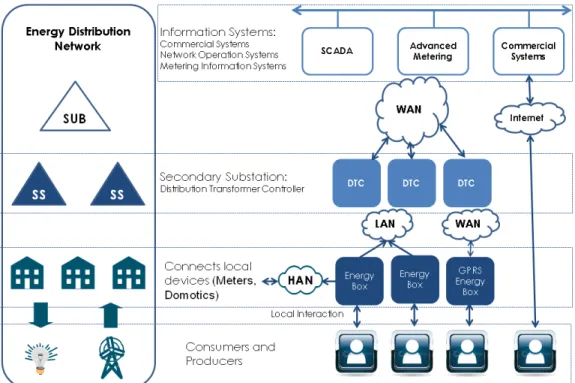
This section presents a high level architecture overview of InovGrid, including the main architec-ture components and their interfaces. The following picarchitec-ture shows a high level diagram where we can identify all the actors starting from the hierarchy top-level components, where we can find se-veral types of applications, through different kind of communications infrastructures, systems and devices, ending at the customer’s homes. All those components communicate among each other providing logical interfaces to transmit information that could be, for instance, meter values or device commands.
Figure 3.1: InovGrid Global Architecture
The information systems (IS) are at the top of hierarchy and their function is to manage all the infrastructure information, collecting and processing all the data but also sending commands and configurations downstream through the network.
The distribution transformer controller (DTC) purpose is to aggregate all the information from the downstream energy boxes and send it to upstream information systems and also permit communi-cations from the upstream systems to the energy boxes. The DTC is installed at switch substations (also called secondary substations) and includes modules for measuring, actuation, processing, interface and communication.
The energy box (EB) is installed at each costumer’s home and includes modules for measuring, actuation, processing, interface and communication. It receives commands and configurations from upstream and send power meter consumption and production figures for upstream architecture components, like the DTC and IS.
These architecture layers are connected by communications technologies and protocols. The net-work that connects the customer, either a consumer or producer, to his EB is called the home area network (HAN). The network that connects the EB to DTC layer is the local area network (LAN). The wide area network (WAN) is the network that connects DTC to IS layer.
3.1.1
Information Systems
The large volume of information generated in the InovGrid infrastructure will be centrally managed by a group of information systems that shall interact with other systems and equipments installed
in distribution grid.
These InovGrid information systems must implement commercial and operational requirements described latter in this document, however, to give an idea of their importance, we highlight the following features for the information systems architecture layer:
• It should manage information of commercial/rate-related nature, required to bill the use of the
grid for each consumer or independent producer. It should also manage the fraud control, which involves the consumption monitoring, energy production, quality of service or compen-sations.
• It should manage the consumption/production related information in order to support the
ser-vices as part of the electricity market, which includes obligations like sending information to marketers, to systems operator or regulatory authority. It should also manage the energy data to enable the calculus of energy balances, technical and commercial losses and determining typical consumption profiles.
• Must consider the infrastructure’s technical management needs as also the rules for the elec-tricity market and manage the quality of data collected by validating, editing and estimating its values.
• Implement operations associated with consumption/production contractual life cycle, including rate changes, cut-off and service restoring, changes in contract power and contract activa-tion/termination.
• It shall actuate on EB devices for temporal limitation of available power, as part of operations
related with managing the distribution grid.
• It should manage and control the public lighting.
• It shall manage technical information necessary to monitor, control and operate the
distribu-tion grid, interacting with SCADA/DMS [20] or others equivalents, and support the systems responsible for managing incidents.
• It should update the configuration, manage events and performance of technical assets that are part of the InovGrid infrastructure, like the DTC and EB.
The systems responsible for grid management may communicate directly with the various DTCs or via this layer of information systems, depending whenever there are constrains related with security, real time monitoring and control functions or technical nature, among others.
The information systems also have the goal to provide the marketers with information to enable them to manage the services to their customers. It means that we have third parties accessing information from the network through this layer of systems which implies that access to information should consider various access levels, making use of authentication mechanisms.
Escalation and modularity are strong design requirement for information systems development be-cause they should be able to support, without affecting the functionalities already working, new features that could derived from the EBs or DTCs, or new services requirements to manage energy related data.
3.1.2
Distribution Transformer Controller
The DTC purpose is to aggregate all the information from the downstream EBs, installed at the customer’s homes, and send it to upstream information systems. It also permits communications from the upstream systems to EBs, specifically to exchange information and software or firmware remote updates.
The DTC is a local control equipment to be installed at switching substations and should include modules for measuring, actuation, processing, interface and communication. Sometimes we might found DTCs at substations, everytime that the switching substations could not support such equip-ment.
Each electrical power transformer, installed at a switch substation, will have an associated DTC that controls environment and electrical variables like voltages or environment temperature. Moreover it can perform actuation in transformer’s switch or turn on and off the public lighting.
The modules that comprise the DTC are.
• CPU is the central processor unit which needs to have the computational power to perform all
the DTC functions.
• Power supply unit.
• HMI is the module responsible for the interface with the user (local access).
• I/O AC are analog inputs for monitoring of electrical currents and voltages.
• I/O DC are analog inputs for temperature monitorization.
• I/O Digital e IO Digital Ex are digital inputs and output for monitorization and actuation.
• LAN communication module represents the connection between the DTC downstream to
energy boxes.
• WAN communication module represents the connection between the DTC upstream to
information systems.
The DTC also supports a serial port RS-232 for communication with public lightingh meter, one interface ethernet and other bluetooth to interface with local user.
Every DTC should support, at least, 1000 downstream energy boxes, however, for this project, it connects, on average, about 200 nodes.
3.1.3
Energy Box
One of the most important components of the InovGrid’s architecture is the energy box. This device will be installed at consumers/producers premises (including all modules for measuring, actuation, processing, interface or communication, among others), so is easy to infer there will be a large number of EBs spread by millions location points, some physical accessible to potential
malicious individuals. This component requires strong security measures since a vulnerability in the architecture could immediately be explored in every installed EB.
The EB is a key element not only due to the large number they represent in the architecture but also because the functionalities implemented in the context of the modern power grids, together with the fact that is expected a large live cycle for such equipments. Therefore the EB will require an evolutionary architecture in order to couple with new functionalities combined with an acceptable production cost. It should respect the following requirements:
• Modularity in a sense that should make possible to quickly and easily configure the most suitable solutions at the best price for consumers;
• Evolutionary, it should couple with services and functionalities evolution without the need to replace the installed equipment. For instance, it should be possibility of setting up value-added services for more demanding customers by simply including additional modules on top of standard core;
• It should operate similarly to “computer-peripherals,” enabling to externally connect or plug other devices to expand the services (e.g. possibility of connecting to more advanced/complex displays).
Additionally we need to consider the following:
• Ability to connect to other external components (advanced display, PDAs/laptops/PCs other meters).
• Ability to have a basic configuration with other minimum services that are indispensable to any device to be set up at the consumption site, taking into account the basic processing and the memory of the central module, namely:
Metrology (active and reactive power and energy);
Standard data processing for the purposes of preparing rates, load diagrams, alarms, events, managing cut-off/restoring orders and change of power, among others;
• Communication with the DTC;
• Standard interface for communication with external devices;
• Power cut-off/connecting mechanisms and control of maximum power;
• Display with basic control and safety information;
• It should have the ability to include and integrate other software modules without the need to replace the equipment, so as to bring about an evolution of services being offered, including:
Additional processing capability (calculations, statistics, profiles, rates);
Home area network communication for interaction with other devices, such as displays, equipment controllers (domotics), sensors and actuators, other meters (e.g. PLC connec-tion [21], ZigBee [22], Wi-Fi [23]);
Micro-production support, with energy management and production control capability; Ability to integrate a demand side management module;
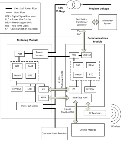
Figure 3.2: Energy Box Architecture
The EB architecture in Figure 3.2 illustrates the modularity and evolutionary capacity features. There are two modules of the EB that deserves further description.
3.1.3.1 Communications Module
The communication module will be responsible for transmission of the information contained in the control and metering module of energy box, either upstream via LAN / WAN network or downstream to the HAN. The data bus to connect the control and metering module with the communications module will be based on interface RS232/Multidrop [24] running on top of it the protocol DLMS [25]. The data bus that makes the interconnection of communication module with other modules of the energy box uses the communication interface EIA 485 [26] and the Modbus [27] RTU communica-tion protocol. This communicacommunica-tion bus shall enable a troughtput greater or equal than 9600 Kbps. The ModBUS is an open standard protocol and has been used in several areas and applications. It can run on top of EIA 232, EIA 485 or Ethernet physical environments. The ModBus has some variants such as MODBUS RTU (the data is sent in binary format, allowing for compression of data
into small packets), Modbus ASCII (the data is sent in the form of characters, consuming more network resources and allowing the message legible), Modbus / TCP (data is encapsulated in TCP frames in binary format).The solution adopted in the current version of the InovGrid is the MODBUS RTU.
The communications module allow remote reading of the records of EB (e.g. consumption, power consumption profile, historical events, quality of service, the measurement point / delivery), as well as changing the configuration parameters (e.g. change of tariff periods, changes in legal time or setting time) and information on the LAN (e.g. network next hop). It also permits changing any password to access the services and update the firmware.
3.1.3.2 Metering Module
The metering and control module consists of an energy meter, single or three phases, connected to the low voltage network, with capacity at least for measuring active and reactive energy consumed and produced. It also includes sufficient storage capacity to retain information values for active and reactive energy consumed and produced, during configurable periods, and to support firmware and software updates.
For the purpose of supporting the low voltage network technical management, the metering and control module, in addition to the limitation of the contracted power, will also have the capability to signal the power limiting module of a technical nature temporary power interruption. For metering and billing activities monitoring purpose the metering module will have a real time clock / calendar, whose accuracy shall be better than 5ppm, synchronized with a similar device existing in the DTC.
3.1.4
Home Area Network
In the functional architecture hierarchy the HAN is the lower layer network connecting the existing devices at the home of each customer to the EB (e.g. allowing interaction with LCD remote actua-tors, partial load shedding devices or home automation). Given the operational cost of installing these devices, usually are considered technologies that do not require the installation of cables, like wireless technologies. An equipment located at each house enables interaction with other meters (e.g. micro-generation, gas and water), with local displays, sensors and actuators (e.g. allowing the selective cutting of loads). However for this work we consider only the interaction with the user, electrical operator staff and equipment.
3.1.5
Local Area Network
The next communication layer in the architecture is the LAN (Local Area Network), this network connects the DTC, placed at switch substations, with EBs installed at the home of every consumer. Each LAN can connect up to a maximum of 1000 devices (on average a LAN will have about 200 nodes on the network), placed along the low voltage network downstream of a switch substation. This network will permit the parameterization of the meters, the reprogramming of the firmware,
changing the contracted power, full or selective cutting and sending loads of meter data, both periodically as on request. Given the possible limitations of the available bandwidth, the network will allow the definition of priority levels so that the information most urgent are not blocked by less urgent. The technology for this network is the Yitran power line communication [28] technology.
3.1.6
Wide Area Network
This network connects the DTC to information systems (technical management, energy mana-gement and metering). The WAN will link approximately 60,000 devices providing bi-directional communications. These DTCs are installed in places geographically dispersed where the cable or fiber communication means to their locations, most of the times, are poor on inexistent, which means that wireless technologies should be adopted. The technology adopted for the current pro-ject implementation is GPRS [29].
3.2
InovGrid Functional Requirements
In this section we describe the InovGrid funtional requirements relevant for the study presented in this work. These requirements will enable the security analysis done in latter section, so it is essencial their description at this phase for a full compreension of this work.
3.2.1
Information Systems Requirements
Now from table 3.1 through table 3.7 we start to describe all the requirements regarding the infor-mation systems.
Req Description
RIS-01 The Information System shall comprise a module for dealing with the acquired information (consumption and production of active and reactive electricity):
Accumulated consumption/production figures, both aggregate and by rate;
• Daily accumulated figures, memorized at 00:00, with a breakdown by rate (daily billing data), upon request;
• Monthly accumulated figures, memorized at 00:00 on the set billing day, with a breakdown by rate (monthly billing data);
• Maximum power figures during the current billing period or
during previous billing periods, with an associated time/date;
• Load diagrams, upon request, for individual facilities or
sets of facilities, based on criteria, such as: association with a certain DTC/DSS (Distribution Transformer Control-ler/Distribution Switch Substation), geographical area, cus-tomer profile, contract options, among others;
• The type of information to be collected from DTC/EB (Distri-bution Transformer Controller/Energy Box) should be confi-gurable, preferably through the use of typical profiles, to be applied to sets of facilities.
Req Description
RIS-02 The Information System should safeguard the information referred to under RSI-01 for a configurable period (at least 3 years). RIS-03 The information pertaining to consumption and production of each
customer should be stored in raw for a given configurable period. RIS-04 The Information System should store the information pertaining to
quality of service for at least 3 years, in a raw state of acquisition and in a statistically treated version in the remaining period. A functionality for validating data pertaining to quality of service, namely those data regarding power outages, should be provided. Among the validations to be implemented, we point out: compa-ring outages recorded in the EBs with those in the corresponding DTCs; signaling situations where the record results from schedu-led, maintenance and commercial interventions; comparing with the information in the incident management system.
RIS-05 The Information System should store the information pertaining to alarm-related events from devices (DTC and EB), for a period of at least 3 years, in response to the requisites of fraud management. RIS-06 All data pertaining to consumption, production and availability for the market shall always be stored in an online consultation system, for a period of time never less than 3 years, and the Information System shall contain a module for consulting such information. RIS-07 All consumption, production data as well as data for availability for
the market shall always be stored in a backup system (DAT, DVD or other), for a period of time never less than 3 years. The Infor-mation System shall contain a module for requests for consulting such information.
RIS-08 The Information System should store all the information pertaining to remote configurations, cut-offs / reconnections for a period of at least 3 years.