EUROPEAN SCHOOL FOR ADVANCED STUDIES IN
REDUCTION OF SEISMIC RISK
ROSE SCHOOL
A
D
ISPLACEMENT
-B
ASED
D
ESIGN
A
PPROACH FOR
S
EISMIC
R
ETROFITTING OF
RC
F
RAMES WITH
S
TEEL
B
RACES
A Dissertation Submitted in Partial Fulfilment of the Requirements for the Master Degree in
EARTHQUAKE ENGINEERING
by
Romain Ribeiro de Sousa
Supervisors:
Dr Miguel Castro and Dr Rui Pinho
The dissertation entitled “A Displacement-Based Design Approach for Seismic Retrofitting of RC Frames with Steel Braces“, by Romain Ribeiro de Sousa, has been approved in partial fulfilment of the requirements for the Master Degree in Earthquake Engineering.
Miguel Castro _________________
i
ABSTRACT
The introduction in Europe of the new regulation for seismic design will impose stricter performance requirements for building structures. This will result in a significant number of existing reinforced concrete structures having inadequate seismic resistance and therefore requiring intervention. One of the possible retrofitting options is the application of steel braces. However, this approach is not widely used due to the lack of seismic regulation in this field. The main goal of this work is the development of a fast and reliable design method that can promote the retrofitting of reinforced concrete frames with steel braces. In the last years, the scientific community has demonstrated that seismic design based in displacements is more adequate and rigorous that the traditional based in forces. Focused in obtaining the fundamental parameters for the application of this new method, it has been realized static and dynamic non-linear analysis in reinforced concrete structures strengthened with concentric steel braces. The results enable the definition of parameters such as displacement profiles, yielding displacements and target displacements among others. Based on the obtained results, it is proposed a displacement based method that enable, in a simple way, to design the retrofitting system so that the hybrid structure presents adequate seismic behaviour.
Keywords: seismic retrofitting, reinforced concrete frames, steel braces, displacement-based design, design method.
ii
A
CKNOWLEDGEMENTS
I would like to thanks to all the persons that, in one way or the other, helped me to overcome all the difficulties during the Masters program.
First of all I would like to thank Prof. Humberto Varum and Prof. Rui Pinho for the support and confidence that they always given to me, and specially, for the motivation and friendship during the last years. Without them, this work would never be possible.
To Dr. Miguel Castro for the knowledge, motivation and close supervision that was always present during the months I worked on this thesis.
To my real friends, João, Mario, Ricardo, António, Kent, Melissa, Andrea, Henrique, Sanja and Gary, you were the joy in my live for the time I was away from Portugal.
To my girlfriend Fatima for the support, friendship and specially love that I always felt, especially in the hardest hours.
Last but not the least, to my family, and in particular to my parents for the financial support, motivation, love and, furthermore, to make me the person I am today.
iii
Poem on the Lisbon Disaster
“UNHAPPY mortals! Dark and mourning earth! Affrighted gathering of human kind! Eternal lingering of useless pain! Come, ye philosophers, who cry, "All’s well," And contemplate this ruin of a world. Behold these shreds and cinders of your race, This child and mother heaped in common wreck, These scattered limbs beneath the marble shafts— A hundred thousand whom the earth devours, Who, torn and bloody, palpitating yet, Entombed beneath their hospitable roofs, In racking torment end their stricken lives.”
(…)
iv
T
ABLE OF
C
ONTENTS
Abstract ... i
Acknowledgements ... ii
Table of Contents ... iv
List of Figures ... vii
List of Tables ... xi
1. Introduction ... 1
1.1. Historical Background ... 1
1.2. Objectives ... 4
1.3. Layout of the Thesis ... 5
2. Reinforced Concrete Steel Braced Frames ... 6
2.1. Overview ... 6
2.2. Bracing Layout ... 7
2.3. Advantages and Disadvantages of Steel Bracing ... 8
2.4. Behaviour of Hybrid RC-Steel System ... 10
2.5. Innovative Bracing Systems ... 11
2.6. Experimental Tests ... 14
2.7. Analytical Studies ... 18
2.8. Concluding Remarks ... 21
3. Seismic Design of Hybrid Systems ... 22
3.1. Lack of Regulations ... 22
v
3.3. Displacement-Based Design ... 28
3.4. Seismic Assessment ... 31
3.5. Rehabilitation Approaches ... 32
3.6. Concluding Remarks ... 34
4. Behaviour of Steel Braced RC Systems ... 35
4.1. Introduction ... 35
4.2. Behaviour of Steel Braces... 35
4.3. Behaviour of RC members ... 37
4.4. Interaction between braces and RC frame ... 39
4.5. Lateral Displacement Profiles ... 42
4.5.1. Geometrical and Material Properties ... 42
4.5.2. Numerical Modelling ... 44
4.5.3. Materials ... 45
4.5.4. Record Selection for Time-History Analysis ... 47
4.5.5. Discussion of Results ... 50
4.5.6. Comparison of Obtained Profiles with Existing Expressions ... 52
4.6. Concluding Remarks ... 55
5. Proposal of a Design Method for Steel Braced RC Frames ... 56
5.1. Introduction ... 56
5.2. Basis of the Method ... 56
5.3. Input Parameters... 58
5.3.1. Yield Displacement (Δy) ... 58
5.3.2. Ultimate Displacement (Δu) ... 61
5.3.2.1. Parameters for the Calculation of the Ultimate Displacement ... 62
5.3.2.2. Column Deformation Capacity ... 62
5.3.3. Lateral Strength (Vy) ... 65
vi
5.3.5. Earthquake Demand ... 66
5.4. Retrofitting Solution ... 66
5.5. Alternative Process... 68
5.6. Concluding Remarks ... 68
6. Validation of the Proposed Method ... 70
6.1. Introduction ... 70
6.2. Structure Characterization and Seismic Vulnerability... 70
6.3. Seismic Assessment ... 71
6.4. Retrofitting Design ... 73
6.5. Verification of the Obtained Results ... 80
6.6. Concluding Remarks ... 82
7. Conclusion ... 83
7.1. Final Remarks ... 83
7.2. Future Developments ... 84
vii
L
IST OF
F
IGURES
Figure 1.1 - Typical strengthening methods (adapted from Sugano (1996)) ... 2
Figure 1.2 - Exterior diagonal bracing applied in tall buildings (John Hancock Building) ... 3
Figure 1.3 - Seismic retrofitting of RC buildings with steel braces ... 4
Figure 2.1 - Bracing configuration ... 7
Figure 2.2 - Bracing patterns ... 7
Figure 2.3 - RC building retrofitted with steel braces (Tokyo Institute of Technology) ... 9
Figure 2.4 - Connection solutions for RC bracing systems ... 10
Figure 2.5 - Typical unbonded brace: layout and response curve (adapted from Di Sarno and Elnashai, 2008) ... 12
Figure 2.6 - K-Bracing with shear links layout ... 12
Figure 2.7 - Example of a dissipative device applied in BRB ... 13
Figure 2.8 - Domiziano Viola school (Potenza, Italy), retrofit with energy dissipating braces in 2002 ... 13
Figure 2.9 - Detail of the X-bracing system and its connection to the RC frame ... 14
Figure 2.10 - Comparison between the analytical force-displacement curves of the unbraced frame, X-bracing and the X-braced frame ... 14
Figure 2.11 - Test setup of brace system (adapted from Youssef et al., (2006)) ... 15
Figure 2.12 - Lateral load-drift curve of the RC frame (left) and Braced frame (right) (adapted from Youssef et al., (2006)) ... 16
Figure 2.13 - Variation of the energie dissipation with lateral drift ... 16
Figure 2.14 - Strain variation of column transverse reinforcement, beam-column joint transversal reinforcement and top beam reinforcement (from left to right) of RC frame (top) and braced frame (bottom) ... 17
viii
Figure 2.15 - Details of connections constructed for experimental investigation ... 17
Figure 2.16 - Relationship between the PGA and the mean storey drift ratio for the existing and rehabilitation cases. ... 19
Figure 2.17 - Bracing system in the central bay: device details and general layout [Varum (2003)] ... 20
Figure 2.18 - Bracing system in the shorter-external bay: device details and general layout [Varum (2003)] ... 20
Figure 3.1 - Shape of the elastic response spectrum defined in EC8 [CEN, 2005] ... 23
Figure 3.2 - Relationship between ductility and force reduction factor (adapted from Pauley et al., 1992) ... 24
Figure 3.3 - Displacement spectra for different levels of damping (adapted from Priestley, 2003) ... 24
Figure 3.4 - Concept of behaviour factor ... 25
Figure 3.5 - Effect of number of storeys on the R value of X-braced frames ... 26
Figure 3.6 - Effect of brace share of base shear on R value of X-braced frames (adapted from Maheri et al., 2003) ... 26
Figure 3.7 - Initial and secant stiffness characterization of hysteretic response (adapted from Priestley et al., 2007) ... 28
Figure 3.8 - Fundamentals of direct displacement-based design ... 29
Figure 3.9 - Capacity spectrum method (adapted from ATC-40 by Varum (2003)) ... 31
Figure 3.10 - Preliminary calculation for retrofit using strengthening and stiffening ... 32
Figure 3.11 - Global modification of the structural system (adapted from Moehle, 2000) ... 33
Figure 3.12 - Local modification of structural components (adapted from Moehle, 2000) ... 33
Figure 4.1 - Behaviour of steel braces (adapted from Longo et al, 2008) ... 36
Figure 4.2 - Axial load-moment interaction diagram (adapted from Collins et al., 1997) ... 37
Figure 4.3 - Influence of axial load on moment-curvature response (Adapted from Collins et al, 1997) ... 38
Figure 4.4 - Example of an axial load-shear interaction diagram ... 38
ix
Figure 4.6 - Forces path of hybrid system ... 39
Figure 4.7 - Independent systems contributing for global base shear (adapted from Queirós et al., 2009) ... 40
Figure 4.8 - Variation in axial load in the compressed RC column ... 41
Figure 4.9 - Schematic response of braced structure (adapted from Della Corte et al., 2008) ... 41
Figure 4.10 - layout of RC frame and elements details ... 43
Figure 4.11 - Stress-Strain relationship for reinforcement (left) and steel braces (right) ... 45
Figure 4.12 - Stress-Strain relationship for poorly confined concrete ... 45
Figure 4.13 - Stress-strain relationship for concrete proposed by Mander et al. [1988]. ... 46
Figure 4.14 - Discretization adopted for the RC braced frame ... 46
Figure 4.15 - Comparison of experimental and analytical response of steel braces ... 46
Figure 4.16 – Acceleration time series of the records selected for time-history analysis ... 49
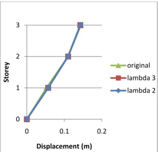
Figure 4.17 - 1st mode shape of the original and the two braced braces analyzed ... 51
Figure 4.18 - Displacement profiles at yielding ... 51
Figure 4.19 - Displacement profiles at failure ... 52
Figure 4.20 - Comparison of displacement profiles from different frames at different stages ... 53
Figure 4.21 - Comparison of displacement profiles obtained with the one resulting from the generalized expressions ... 54
Figure 4.22 - Comparison of analysis results with new expression ... 55
Figure 5.1 - Preliminary calculation for retrofit using strengthening and stiffening ... 57
Figure 5.2 - Identification of yield displacement on steel braced RC frames ... 58
Figure 5.3 - Brace frame model: a) forces; b) lateral deformation; c) vertical deformation (adapted from Moon et al., 2007) ... 59
Figure 5.4 - Influence of frame rotation in braces behaviour ... 60
Figure 5.5 - Contribution of displacement components to total lateral displacement (adapted from Sozen et al, 2004) ... 63
x
Figure 5.6 - Evolution of moments: a) bare frame, b) braced frame ... 63
Figure 5.7 - Moments evolution in RC columns with and without bracing system ... 64
Figure 5.8 - Comparison of an RC column capacity considering different contra-flexure lengths ... 64
Figure 5.9 - M-N interaction plot (adapted from RESPONSE-2000 Program) ... 65
Figure 5.10 - Illustration of a base shear-target displacement plot for different brace properties ... 66
Figure 5.11 - Evaluation of the seismic behaviour for two different solutions: a) unsatisfactory seismic behaviour; b) satisfactory behaviour ... 67
Figure 6.1 – RC frame ... 71
Figure 6.2 – Beam and column cross-sections ... 71
Figure 6.4 - Capacity curve of the MDOF ... 72
Figure 6.5 - Bilinear curve of the SDOF ... 72
Figure 6.6 - Application of the CSM procedure ... 73
Figure 6.7 - History of axial loads in the pushover analyze ... 73
Figure 6.8 - M-N interaction diagram (adapted from RESPONSE-2000) ... 74
Figure 6.9 - Solution 1 ... 75
Figure 6.10 - Solution 2... 76
Figure 6.11 - Solution 3... 76
Figure 6.12 - Comparison of the design displacements for all studied solutions ... 78
Figure 6.13 - Superposition of response spectra with the performance points of braces 5 and 4 ... 79
Figure 6.14 - Superposition of response spectra with the performance points of braces 3 and 2 ... 80
Figure 6.15 - Superposition of response spectra with the performance points of brace 1 ... 80
Figure 6.16 - Comparison of the calculated target point with the capacity curve of the braced structure ... 81
Figure 6.17 - Representation of the Capacity curve with the corresponding bilinear representation ... 82
xi
L
IST OF
T
ABLES
Table 2.1 - Values of the parameter γ for existing and rehabilitated frames R1 to R6 ... 19
Table 3.1 - Tentative values of R factor for steel-braced, RC frame dual systems ... 26
Table 3.2 - q values obtained for different RC frames and steel braces [Queirós et al., (2009)] ... 27
Table 4.1 - Properties of the braces adopted in the analysis ... 43
Table 4.2 - Earthquake records used in the analysis ... 47
Table 4.3 - Resume of scale factors obtained in dynamic analysis ... 50
Table 4.4 - Fundamental periods of vibration of the analyzed frames ... 50
Table 6.1 - Basic properties of selected steel braces ... 74
Table 6.2 – Global yield displacement of the frame for different braces ... 75
Table 6.3 - Maximum compressive axial load in the RC column for different brace properties ... 76
Table 6.4 - Minimum compressive axial load in the RC column for different brace properties ... 76
Table 6.5 - Maximum deformation capacity for each RC column in solution 1 ... 77
Table 6.6 - Maximum deformation capacity for each RC column in solution 2 ... 77
Table 6.7 - Maximum deformation capacity for each RC column in solution 3 ... 77
Table 6.8 - DBD parameters for all solutions studied ... 78
Table 6.9 - Values of ductility and equivalent viscous damping for all studies solutions ... 79
1
1. I
NTRODUCTION
“The first and most important thing to be done (...) is to learn thoroughly what it is that I have undertaken”
Frountinus (Curator Aquarum of ancient Rome)
1.1. H
ISTORICAL
B
ACKGROUND
Recent seismic events such as the 1985 Mexico, the 1994 Northridge, the 1995 Kobe and the 1999 Kocaeli earthquakes induced severe damage to non-ductile reinforced concrete (RC) buildings proving that many constructions located in seismic zones are unable to withstand moderate to severe earthquakes and therefore observe significant damage and contribute to significant loss of lives.
After big earthquake events such as those mentioned above, the scientific community focused their attention to better understand the phenomenon. As a result, the design codes have experienced significant developments over the years. At the same time researchers have also concentrated to studying various strengthening techniques to enhance the seismic performance of existing buildings.
Framed systems are extensively used for building structures in earthquake-prone regions because of their potential for good seismic performance. Many existing RC structures worldwide were designed for gravity load only, with inadequate lateral load resistance, lateral stiffness and poor detailing of the reinforcement.
Wyllie (1983) defined seismic retrofitting as the “judicious modification of the structural properties of an existing building in order to improve its performance in futures earthquakes”.
2 The two main approaches for structural rehabilitation consist of: i) adding new structural elements such as walls and steel braces, and ii) strengthening of structural elements by encasing with steel, FRP or RC jackets. In recent years, some new trends, which are called passive energy dissipating devices, have appeared to enhance the seismic behaviour of existing structures [Aydin et al., 2008]. Sugano (1996) summarized the most common strengthening methods in a flowchart, as shown in Figure 1.1:
Figure 1.1 - Typical strengthening methods (adapted from Sugano (1996))
Global intervention methods may represent a more cost-effective strategy than upgrading of the existing components, especially if the disruption of occupancy and the demolition and replacement of partitions, architectural finishes and other non-structural components are considered [Fardis, 1998]. This is particularly true for structures where no horizontal load-path is available, or in the case of all structural members being extremely flexible. In such cases the methods described below may indeed provide an optimum solution [Pinho, 2000].
While many of these techniques can effectively improve the lateral stiffness and strength of the structure, adequate seismic behaviour will be obtained only if the retrofitted structure can satisfy the strength and ductility imposed by the earthquake [Pincheira et al., 1995]. Independently of the retrofitting scheme, besides the increment in stiffness or strength of the existing structure, not every retrofitted structure performs adequately under any seismic event considered [Jordan, 1990].
Traditionally, steel bracing systems have been used to increase the lateral load resistance of steel structures. In the past two decades, a number of reports have also indicated the
3 effective use of steel bracing in RC frames [Youssef et al., 2007; Badoux et al., 1990]. Steel bracing of RC buildings started as a retrofitting measure to strengthen earthquake-damaged buildings or to increase the load resisting capacity of existing buildings [Maheri et al., 2003].
The bracing techniques adopted in the past fall into two main categories, namely (i) external bracing and (ii) internal bracing [Maheri et al., 2003].
However, while the structural efficiency provided by diagonal braces was well recognized, their aesthetic potential was not entirely appreciated. Thus, diagonals were generally embedded within the building cores which were usually located in the interior of the building [Moon et al., 2007].
A major departure from this design approach occurred when braced tubular structures were introduced in the late 1960s. In the 100-storey tall John Hancock Building in Chicago, the diagonals were located along the entire exterior perimeter frames (Figure 1.2) of the building in order to maximize their structural effectiveness and capitalize on the aesthetic innovation.
Figure 1.2 - Exterior diagonal bracing applied in tall buildings (John Hancock Building)
Others examples of this retrofitting scheme can be found for example in Mexico City and California (Figure 1.3). According to Moon et al. (2007) this strategy is much more effective than confining diagonals to narrower building cores.
4
Figure 1.3 - Seismic retrofitting of RC buildings with steel braces
Increased architectural flexibility, reduced weight of the structure, easy and speed of construction and the ability to choose more ductile systems can be considered as the main advantages of steel bracing in comparison with strengthening based on the inclusion of RC shear walls [Maheri et al., 2008].
Despite the several experimental and analytical studies conducted [Maheri et al., 1997; Badoux et al., 1990] in the last years trying to understand the behaviour of this type of hybrid structures, the fact is that only a few have resulted in proposal of values for the so call behaviour factor to be use in the design process. Moreover, due to the discrepancy of the results, the values obtained in past works do not provide enough confidence to the designer. In fact, as it will be discussed herein, some authors support that a force-based design approach is not entirely suitable for this type of structures.
1.2. O
BJECTIVES
The aim of the present work is to develop a displacement-based design procedure for the seismic retrofitting of RC frames with steel braces that overcomes the limitations identified with traditional force-based design procedures. The methodology to be proposed should be simple and easy to apply by the designer but should conduct to reliable structural solutions. Moreover, it should take into account the complex interaction between the steel braces and the RC elements. In addition to this main objective, the research also intends to describe the lateral behaviour of steel braced RC frames, particularly in terms of the lateral deformation characteristics of this type of structural systems.
5
1.3. L
AYOUT OF THE
T
HESIS
The dissertation is organized in seven chapters. This chapter (Chapter 1) provides a general introduction to the topic along with the main objectives expected from the research. Chapter 2 reviews past experimental, numerical and analytical studies performed on steel braced RC frames. The current situation regarding the seismic design of this type of structures is discussed in Chapter 3. The limitations associated with the application of traditional force-based procedures in the seismic design of steel RC braced frames are highlighted. In Chapter 4 the results from numerical studies are used in order to describe the behaviour of steel RC hybrid systems, particularly the interaction between the steel braces and the RC elements. A parametric study is also described which aimed at the characterisation of the lateral deformation mode shapes of this type of structural systems. In Chapter 5 a new displacement-based design method for hybrid systems is proposed which aims at producing retrofitted solutions with better and more predictable seismic performance. The new design method is applied in Chapter 6 to design the bracing system of a regular RC structure that is found to have inadequate strength to resist a given design earthquake. Several solutions are tested comprising different bracing layouts and brace cross-sections. The accuracy of the method is confirmed through a non-linear static analysis of the adopted solution. In Chapter 7 the main conclusions of the research are summarised along with some suggestions for future research on this topic.
6
2. R
EINFORCED
C
ONCRETE
S
TEEL
B
RACED
F
RAMES
“To find the answer, you must know the answer”
The third principle of engineering (1939)
2.1. O
VERVIEW
To resist lateral earthquake loads, shear walls are commonly used in RC framed buildings, whereas steel bracing is most often used in steel structures. In the past two decades, a number of reports [Maheri et al., 1997; Badoux et al., 1990] have indicated the effective use of steel bracing in RC frames. Steel bracing of RC buildings started as a retrofitting measure to strengthen earthquake-damaged buildings and/or to increase the lateral load resistance of existing buildings. The steel system technique was firstly used to rehabilitate an existing RC structure in Japan during the 80´s [Badoux et al., 1990].
The bracing methods adopted in the past fall into two main categories, namely (i) external bracing and (ii) internal bracing. In the external bracing system, existing buildings are retrofitted by attaching a local or global steel bracing system to the exterior frames. Architectural concerns and difficulties in providing appropriate connections between the steel bracing and RC frames are two of the shortcomings of this method. In the internal bracing method, the buildings are retrofitted by incorporating a bracing system inside the individual bays of the RC frames. The bracing may be attached to the RC frame either direct or indirectly.
In the indirect internal bracing, a braced steel frame is positioned inside the RC frame. The indirect internal bracing method can be an expensive solution resulting from the difficulties resulting from the fixation of the braced frame to the RC frame. Another limitation of this method is that the retrofitted frame is susceptible to dynamic effects due
7 to interaction between the steel frame and the concrete frame. To overcome the shortcomings of the indirect internal bracing, Maheri and Sahebi proposed a direct connection between the steel bracing and RC frame without the need for an intermediary steel frame [Maheri et al., 2003].
2.2. B
RACING
L
AYOUT
The definition of an appropriate bracing layout is important because the effect of retrofitting on the flow of the forces through the structures should be as simple as possible, in order to avoid load concentration or potential weak zones. From a structural point of view, it may be desirable to brace as many bays as possible, so that increases in strength and stiffness are uniformly distributed within the existing RC structure.
However, it is often preferable not to brace the end bays due to two main reasons. Firstly, because the end bays may be shorter than intermediate bays, making bracing geometry difficult. Secondly, because a typical interior column can resist overturning forces better than an exterior (end) one [Badoux et al., 1990].
In the Figure 2.1 and Figure 2.2, it is possible to observe some configurations and patterns for bracing systems proposed by Badoux et al. (1990).
Figure 2.1 - Bracing configuration
8
2.3. A
DVANTAGES AND
D
ISADVANTAGES OF
S
TEEL
B
RACING
When an engineer is faced with an assessment and retrofitting problem, he must decide the strategy based on many factors such as: aesthetics of steel bracing, speed of constructing, economy, occupancy of the building, efficiency…
Each retrofitting technique has its advantages and disadvantages. Regarding the use of steel bracing systems, one of the advantages is the fact that most of the construction work can be performed on the exterior of the building in order to speed erection and to minimize disruption of the occupants and comprise the possibility of including openings. This can be a very effective method for global strengthening of the building. Concentric or eccentric bracing schemes may be used in selected bays of an RC frame to provide a significant increase of the lateral capacity of the structure. Normally, no intervention to foundations is required and its installation is not asdisruptive as that of shear walls [Pinho, 2000]. However, in some cases it might be necessary to verify if the additional loads imposed by the braces will not affect the capacity of the foundations.
At the same time the erecting of the braces in the perimeter will increase the capacity of the building to resist to torsional forces during the earthquake. The loss of space and accessibility in the retrofitted building and the cost of interior remodelling are minimized as well. These may be a significant advantages compared to other retrofitting schemes. Another advantage is the small increment in the mass comparatively with the existing building or with that of adding new RC walls, specially comparing with the increase in stiffness [Abou-Elfath et al., 2000; Badoux et al., 1990].
Finally it must be pointed out that one of the most critical aspects found in buildings with low seismic resistance is the potential for the formation of soft-storeys particularly when there are no infill walls in the ground storey. In such cases, bracing the bare bays may result in a fast, economical and efficient way to avoid this undesirable collapse mechanism.
On the other hand, steel braces have also some drawbacks, namely the aesthetical changes caused to the original structure. The structure shown in Figure 2.3 is a good example of harmony between the retrofitting scheme and the architectural issues.
9
Figure 2.3 - RC building retrofitted with steel braces (Tokyo Institute of Technology)
Another important issue that can be seen as a disadvantage is the connection between the bracing system and the RC frame [Maheri et al., 2008]. This link between the two systems is
responsible for the transmission of the loads carried by the braces to the structure and plays a fundamental role on the success of the strengthening intervention [Youssef et al., 2006].
The advantage of connecting the steel bracing system directly to the RC frame is that the connection is generally easy to execute and therefore inexpensive. However, the connection should be strong enough to safely transfer the loads between the braces and the RC frame.
Maheri et al. (1997) investigated the behaviour of various connection schemes. The connections shown in Figure 2.4 represented different arrangements for existing frames and were found to have an adequate behaviour. Moreover, experimental investigation indicated that the connections can be designed successfully by combining the current guidelines and the provisions set by codes of practice for designing brace/steel frame connections and base plate/RC member connections [Maheri et al., 2003].
10
Figure 2.4 - Connection solutions for RC bracing systems
Finally, the lack of design models can be seen as the main disadvantage in the application of this retrofitting method.
2.4. B
EHAVIOUR OF
H
YBRID
RC-S
TEEL
S
YSTEM
Several studies demonstrated that in a steel-braced RC frame deforming laterally, the bracing system and the RC frame can be considered as coupled independent systems adding their lateral strength and stiffness [Badoux et al., 1990; Di Sarno et al., 2009]. Some authors like Di Sarno and Manfredi (2009) stated that the new bracing system should absorb and dissipate large amount of hysteretic energy under earthquake ground motion, at the same time that the original system is capable to withstand the vertical loads and respond elastically under earthquakes loads [Di Sarno et al., 2009]. In the present study however, for economical and structural reasons, it is believed that the original RC system should still be allowed to undergo inelastic deformations.
The bracing system can compensate for inadequate frame strength and/or stiffness, but cannot change the frame’s failure mode. As explained subsequently, increasing the capacity of the braces will increase the axial forces in the columns and this will lead to a possible reduction in the deformation capacity. It is possible that the solution adopted for
11 the braces could lead to a premature failure of the column. For these cases, a complementary solution may be adopted or even adopt a completely different retrofitting solution.
In some investigations, bracing was applied to the concrete frame indirectly through a steel-frame, itself confined in the concrete frame. This rather elaborated “indirect bracing system” can be costly and economically non-viable [Maheri et al., 1997], but in order to avoid the problems referred above, it may represent in some cases a good solution.
2.5. I
NNOVATIVE
B
RACING
S
YSTEMS
In recent decades many studies were developed as an attempt to improve the original steel bracing systems. Many of these innovating systems have arisen to overcome possible inconveniences identified previously. This chapter intends to summarize some of the “upgrades” introduced in the steel bracing systems.
Buckling Restrained Braces
One of the disadvantages of traditional braced systems may be overcome whether the occurrence of buckling for the metallic braces in compression is inhibited by using unbonded braces (UB) or buckling-restrained braces (BRB). These system exhibits large and stable hysteretic dissipation (Figure 2.5). The UBs are braces where the core is placed within a hollow section member, filled with either mortar or concrete [Di Sarno et al., 2009].
BRBs are an efficient solution to the problem of the limited ductility of classical concentric bracing, thanks to the avoidance of global compression buckling. Experimental and numerical simulations prove that the energy dissipating capacity of BRBs is extremely high [Di Sarno et al., 2009]. They are basically made of very slender steel plates, forming the core of the BRB, which are allowed to yield both in tension and compression. The slender plates are inserted inside steel rectangular or square hollow section profiles, which provide the restraining effect against lateral buckling. In the most classical form, the restraining tube is filled with concrete and an unbonding layer is placed at the contact surface between the core plates and the filling concrete, thus the name ‘unbonded brace’ of this version [Mazzolani, 2007].
12
Figure 2.5 - Typical unbonded brace: layout and response curve (adapted from Di Sarno and Elnashai, 2008)
K – Bracing with shear links
The K-bracing with shear-link system consist of an eccentrically braced steel assembly with a vertical shear-link located at mid-span of either the upper or bottom floor beam (Figure 2.6).
Figure 2.6 - K-Bracing with shear links layout
Comparing this system with the traditional X-bracing scheme, this will have a lateral load resistance similar to the initial resistance but with a significant increased energy dissipating capacity. Hence, the risk of overloading the foundation can be significantly reduced [Bouwkamp et al, 2000].
Bracing System with Dissipative Devices
In the dissipative brace (Figure 2.7), the energy dissipation is concentrated in the brace itself or in one opposite element (dissipator) in a way to avoid damage in the main structural elements (beams and columns) [Antonucci et al., 2009]. The device can increase both the stiffness and damping of the overall system, consequently leading to a reduction of the deformation demand.
13
Figure 2.7 - Example of a dissipative device applied in BRB
Passive energy dissipation devices or shear links may also be used in conjunction with the bracing to efficiently increase dynamic damping. However, if the bracing system increases the stiffness of the frame considerably, the efficiency of the damping mechanism is compromised since these normally require large levels of deformation to be cost-effective [Fardis, 1998]. Figure 2.8 illustrates one example of application of bracing systems with dissipative devices.
Figure 2.8 - Domiziano Viola school (Potenza, Italy), retrofit with energy dissipating braces in 2002
Post Tensioned Braces
Inrecent years, it has been shown that the seismic performanceof existing buildings can be enhanced considerably by bracing with post-tensioned rods or cables [Pinho, 2000]. This upgrading technique has severaladvantages, which include architectural versatility, low cost and fast construction.Furthermore, it does not add a significant mass to the existing building.
This system involves the addiction of post-tensioned rods that will yield for small levels of deformation, allowing energy dissipation at an early stage of a large seismic event.
14 However, the initial brace prestressing induces additional forces in the structure modifying the internal force distribution. This needs to be considered, especially for serviceability limit states [Pinho, 2000].
2.6. E
XPERIMENTAL
T
ESTS
Maheri, et al. (2003) carried out monotonic tests on reduced scaled steel X-Braced RC frames. The objective of the study was to examine several response and design parameters, namely load capacity, stiffness, ductility and behaviour factor (R).
Figure 2.9 - Detail of the X-bracing system and its connection to the RC frame
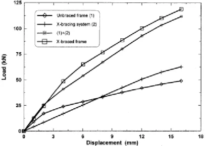
Test results showed that the load capacity of an existing ductile frame can be increased to the desired level by directly adding a bracing system to the frame, without the need for prior strengthening of the existing frame (Figure 2.10).
Figure 2.10 - Comparison between the analytical force-displacement curves of the unbraced frame, X-bracing and the X-braced frame
15 The study demonstrated that load capacities of the braced frames are higher than the summation of the capacities of the unbraced frame and the bracing system. Two factors can be attributed to the increase in the strength of the RC frame. Firstly, in the braced frame, because of the bracing system, the formation of the first plastic hinge in the RC beams occurs at higher loads. In other words, the bracing system increases the yield capacity of the RC frame members. Secondly, the rigid connections between the brace and the frame add to the strength of the frame mainly by reducing the effective lengths in beams and columns.
The test results led the authors to conclude that X-bracing is more suitable for a strength-based design. However, the relatively small post-yield capacity and the somewhat brittle failure mode of the X-braced frame make this system unfavourable for a ductile design. It was found that steel bracing reduced the ductility and the performance factor (R) of a ductile RC frame. The ductility capacity was reduced from 4.19 to 2.71. Similarly, the R factor was reduced from 12.1 to 4.3.
Youssef et al., (2006) conducted experimental tests that proved the brace system as a good retrofitting solution.
Figure 2.11 - Test setup of brace system (adapted from Youssef et al., (2006))
The results presented in Figure 2.12 showed that in the braced system, the pinching was less significant, indicating an overall better seismic performance. It was also observed that the lateral load capacity was significantly increased and the ultimate drift was slight reduced.
16
Figure 2.12 - Lateral load-drift curve of the RC frame (left) and Braced frame (right) (adapted from Youssef et al., (2006))
Furthermore it was observed that at low drift levels, the energy dissipated by the braced system was lower than that dissipated by the RC frame. This was mainly attributed to the initial high stiffness of the braced frame. At higher levels of drift, the authors of the study found that the energy dissipated by the braced frame was much higher than that dissipated by the RC frame.
Figure 2.13 - Variation of the energie dissipation with lateral drift (adapted from Youssef et al.,
(2006))
The analysis of the reinforcement revealed that strains reduced significantly when steel braces were applied to the RC frames (Figure 2.14). This observation allowed the authors to conclude that the forces in the braced members were mainly transferred to the RC beams and columns as axial forces and hence indicating that shear failure should not be expected.
17
Figure 2.14 - Strain variation of column transverse reinforcement, beam-column joint transversal reinforcement and top beam reinforcement (from left to right) of RC frame (top) and braced frame
(bottom)
Recognized as one of the issues to address in the retrofitting process of RC frames, some authors (e.g., Maheri and Hadjipour (2003)), carried out experimental investigations on the connection between steel braces and RC frames.
Figure 2.15 - Details of connections constructed for experimental investigation
The study indicated that these connections could be designed successfully by combining guidelines and provisions set out by codes of practice for designing brace/steel frame connections and base plate/RC member connections [Maheri et al., 2003].
Experimental tests, conducted in 2006 allowed to conclude that connections could be designed using a similar procedure to that for braces in steel structures. In that study, brace member connections, including welds and head studs, exhibited adequate behaviour [Youssef et al., 2007].
18 Di Sarno and Manfredi (2009) performed in situ tests on full scale RC frames retrofitted with Buckling Restrained Braces. The results obtained from an energy analysis were found to be useful to quantify the contribution of the braces and the bare RC frame to the global hysteretic response.
2.7. A
NALYTICAL
S
TUDIES
Analytical studies performed in the past provided insights into the effectiveness of various global retrofitting schemes. For example, Pincheira and Jirsa (1995) carried out inelastic static and dynamic analysis of three prototype buildings. Retrofit schemes included the post-tensioned bracing, structural steel bracing, and infill walls of reinforced concrete frames. The buildings selected for study were 3-, 7- and 12-storey high frames of reinforced concrete. The prototype designs contain typical reinforcement details of older frames and represent low and medium rise construction in regions of high seismicity in US. The authors of the study also evaluate the displacements capacity of the mentioned structures for different earthquakes and different retrofitted solutions.
The study concluded that there is not a unique solution and that several difference retrofit schemes can be designed to provide effective seismic resistance. Satisfactory response was obtained only for schemes that adequately controlled interstory lateral drifts to levels that did not cause significant damage the existing structure. For bracing systems that resulted in controlled lateral drifts, the level of axial forces induced by steel braces would adversely affect the lateral strength of the existing reinforced concrete member or, in some cases, exceed the axial capacity of the member.
Abou-Elfath and Ghobarah (2000) conducted analysis in different configurations and distribution of steel braces in a nonductile RC building. The followed six different frames were tested, where the parameter Γ indicates the brace distribution per floor of the frame. The fists parameters evaluated were the lateral load capacity and variation in drift ratios over the height. To do that, the parameter γ is introduced to measure the variation in the storey drift ratios from the average storey drift:
(1) Where Si is the storey drift ratio of the ith storey, Savg is the average storey drift ratio and n is the total number of stories. The value of γ equal to 0 represents equal storey drift ratio for all the building stories. The value of γ equal to 1 indicates that one given storey is the only source of overall building deformation (soft storey).
This parameter was useful for comparing the plastic mechanism of buildings with different heights or different rehabilitation options. Moreover, this parameter was also useful in
19 evaluating the distribution of braces over the height of the building [Abou-Elfath et al., 2000].
Table 2.1 - Values of the parameter γ for existing and rehabilitated frames R1 to R6
The second rehabilitation case with the lowest value of v exhibited the best performance of all the rehabilitation cases, while the fourth rehabilitation case with the largest value of
v exhibited the poorest performance.
The following figure represents the variation of the mean storey drift ratio of the analyses using 12 earthquakes. The results in the figures show that there is a direct correlation between the building seismic performance and the level of the parameter v (listed in table above).
Figure 2.16 - Relationship between the PGA and the mean storey drift ratio for the existing and rehabilitation cases
Tests conducted by Abou-Elfath and Ghobarah (2000) in structures with different bracing configuration and with changing the braces capacity over the height, showed that adding steel bracing uniformly distributed over the height may not represent the optimum solution. It is possible to improve the plastic mechanism of the rehabilitated building by special arrangement of the lateral strength distribution along the frame height to force most of the members to contribute to the building overall deformation. This can be also achieved by increasing the number of braced bays.
The degree of improvement in the seismic performance of the rehabilitated building depends significantly on the level of increase of the load carrying capacity as well as on the change in seismic demand that results from the associated stiffness increase. In general the improvement in the building capacity is superior to the increase in seismic demand. At
20 the same time, increasing too much the braces capacity may lead to expensive solutions and axial loads in the concrete columns that may not be accepted. By increasing the number of braced bays the loads on the reinforced concrete columns decrease and column failure may be avoided [Abou-Elfath et al., 2000].
In some of the analytical studies available the results may not represent real structural scenarios. In many of the studies, the retrofitted schemes exhibited large deformation capacity and large ductility in comparison with the original structures. That was mainly due to the use of models that neglected important factors such as P-Δ effects and the interaction of the axial force with both moment and deformation capacities of the RC member [Abou-Elfath et al., 2000].
Varum (2003) investigated several strengthening techniques on existing buildings. Amongst others, he studied the application of X- and K-bracing with dissipative devices. The layouts and device details of the structures investigated are plotted in Figure 2.17 and Figure 2.18.
Figure 2.17 - Bracing system in the central bay: device details and general layout [Varum (2003)]
Figure 2.18 - Bracing system in the shorter-external bay: device details and general layout [Varum (2003)]
21 Seismic vulnerability functions were calculated to investigate the behaviour of the retrofitted solutions. Seismic vulnerability functions of structural systems are expressions that relate earthquake intensities with quantitative measures of their probable consequences on the performance of those systems.
The numerical analysis for the retrofitted frame case (K- and X-bracing with rubber dissipator) allowed the author to conclude that the light retrofitting solution appeared to be effective for low, medium and high seismic intensities, but not particularly effective for very high intensities when infill panels exist. This retrofitting system was designed for the bare frame and it was very effective for that case. However, according to the author of the study, a more accurate design should consider the infill panels. Additionally, the retrofitting system led only to a small increase of the storey shear forces. Finally, an important increase on the energy dissipation capacity was observed. The contribution of the RC frame, of the infill panels and of the retrofitting devices to the total energy dissipation was approximately equal.
2.8. C
ONCLUDING
R
EMARKS
In this chapter an overview of steel braced RC frames was presented. Several experimental and analytical studies performed on this topic were reviewed. The main conclusions resulting from past studies are summarised below:
1. Both experimental and analytical studies indicated that the adoption of steel braces to retrofit existing RC buildings is a good strategy and that, in some situations, that solution may be more suitable in comparison with other more traditional retrofitting solutions.
2. The lateral resistance and stiffness of RC frames significantly increases when steel braces are added to the structure. The improvements are visible even when “light” braces are considered.
3. Besides the loss of local ductility observed in the RC column elements, previous research demonstrated an increase in the ductility capacity of the global structure. 4. A good performance of the connections between the two systems is expected if
traditional guidelines and provisions set out by codes of practice are applied. Despite the many advantages of retrofitting RC frames with steel braces, an important factor can limit the use of this technique. In effect there is not yet available a simple and accurate design method that can be used by practitioners. In the next chapter the current situation concerning the seismic design of RC frames retrofitted with steel braces will be discussed.
22
3. SEISMIC DESIGN OF HYBRID SYSTEMS
“The truth is, the science of Nature has been already too long made only a work of the brain and the fancy: It is now high time that it should return to the plainness and soundness of observations on material and obvious things.”
Robert Hooke (1635 - 1703)
3.1. L
ACK OF
R
EGULATIONS
Traditionally, structural seismic design has been based primarily on forces. The reasons for this are largely historical, and started to how we design for other actions, such as dead and live load [Priestley et al., 2007]. This is mainly the reason why, seismic design is currently codified by structural codes and standards of practice, using the so-called “force-based” design (FBD). In this design, the earthquake action is considered as equivalent static forces with different intensity and distribution over the height of the structure as a function of the earthquake shaking intensity at the site of interest and the structural type.
In the preceding chapter several studies, involving the behaviour of steel braces and RC braced structures, were presented in order to better understand the behaviour of this type of structures and its main advantages and disadvantages. Despite the good seismic behaviour of the retrofitted structures [Badoux et al. in 1990] there is still a lack of design rules for hybrid structures in seismic codes.
In order to overcome this situation, several researchers conducted studies to find important parameters such as behaviour factor (q), also known as response modification factor (R), associated to this type of structures so that they might be adopted in FBD methodologies. A brief summary of FBD is presented in the next section.
23
3.2. F
ORCE
-B
ASED
D
ESIGN OF
H
YBRID
S
TRUCTURES
Seismic design arises historically as an extension of the design for static loads. Despite the evolution in the seismic engineering field over the past decades, particularly the development of performance-based design concepts, in general the codes of practice are still based on forces. In simple terms, Force-Based Design (FRD) consists of the calculation of a design base shear which is a function of the fundamental period of the structure, of a behaviour factor that takes into account the ductility expected to develop within the structure and also a function of an acceleration response spectrum (Figure 3.1). The base shear is then applied to the structure as set of equivalent static forces which are adequately distributed over the height of the structure. Section and member design checks are then carried out along with some simple lateral deformation checks.
Figure 3.1 - Shape of the elastic response spectrum defined in EC8 [CEN, 2005]
The base shear is calculated by multiplying the total mass of the building by the design spectral acceleration. The design acceleration is calculated by dividing the spectral acceleration by the behaviour factor (q).
(2) In order to estimate the actions on the structure the base shear is distributed over the height of the building, typically according to the shape of the fundamental mode.
It is accepted that damage can be related to material strains, and that material strains can be related to maximum response displacements, but not to response accelerations. It would thus seem important for design procedures to emphasize the importance of estimating peak displacement response. In fact, the situation pertaining ten years ago was characterized by uncertainty in the estimation of deformations of inelastic systems. The normal approach involves modification of the displacements of the corresponding elastic system of equal initial stiffness and unlimited strength. The most common assumption was the equal displacement approximation, which states that the displacement of the inelastic
24 systems is the same as that of the equivalent system with the same elastic stiffness, and unlimited strength. The equal displacement approximation is known to be non-conservative for short-period structures. As a consequence, some design codes apply the equal energy approximation when determining peak displacements.
Figure 3.2 - Relationship between ductility and force reduction factor (adapted from Pauley et al., 1992)
It would appear that it should be a comparatively simple matter to determine, on the basis of inelastic time-history analysis, which rule is correct. Unfortunately, it was found that all are correct at some part of the period range of structural response, and all are wrong at other periods. This is pointed out in the Figure 3.3.
Figure 3.3 - Displacement spectra for different levels of damping (adapted from Priestley, 2003)
Based on the above principles, (q) or (R), is a force reduction factor used to reduce the linear elastic response spectra to the inelastic response spectra. In other words, it is the ratio of the strength required to maintain the structure elastic to the inelastic design strength of the structure expected to observe a pre-defined displacement ductility demand. The behaviour factor, therefore, accounts for the inherent ductility and overstrength of a structure and the difference in the level of stresses considered in is design.
25 In Figure 3.4 is represented a typical lateral response curve of a ductile structure. Vel represents the base shear if the structure were to respond elastically, Vy represents the maximum base shear of the ductile structure and, finally, V1y represents the base shear at the formation of the first plastic hinge. The horizontal axis refers to the displacements for the corresponding loading level referred previously.
Figure 3.4 - Concept of behaviour factor
Based on the figure, the behaviour factor (q or R)can be defined as:
(3)
Di Sarno and Manfredi (2009) found values for the behaviour factor for BRBs between 4.5 and 6.5, that are in agreement with those estimated for steel framed structures [Di Sarno
et al., 2009].
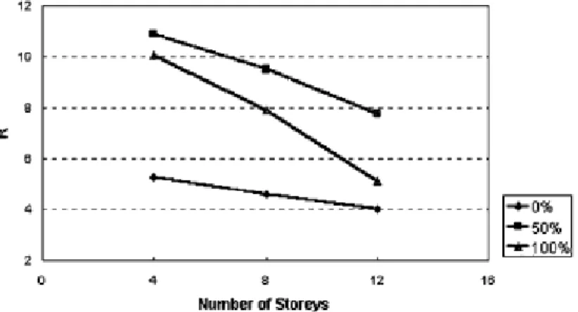
In 2003, Maheri and Akbari investigated the variation of behaviour factor (R) by doing numerical tests on RC buildings with 4-, 8- and 12-storeys and in each one of these, they changed the bracing layout in a way such that the braces could carry 0%, 50% and 100% of the total base shear. The tests were conducted for X braces and Knee braces. In Figure 3.5 it can be seen that the number of storey appear to be the predominant variable affecting the R factor in comparison with the type of bracing system and the share of bracing from the applied load.
26
Figure 3.5 - Effect of number of storeys on the R value of X-braced frames (adapted from Maheri et
al., 2003)
However, the Figure 3.6 indicates that the bracing system adopted plays an important role. This factor is somehow expected since the characteristics of the braces, namely the strength capacity in tension and in compression, will govern both the yielding and ultimate capacity of the existing structure, and this way, the level of ductility capacity.
Figure 3.6 - Effect of brace share of base shear on R value of X-braced frames (adapted from Maheri
et al., 2003)
Tentative R values for steel-braced RC frames with intermediate ductility are presented in Table 3.1.
Table 3.1 - Tentative values of R factor for steel-braced, RC frame dual systems
A relationship between the R factor determined and the shear strength contribution for the columns to resist lateral seismic loads was observed. The greater the shear strength contribution of the RC columns, the less the overstrength developed. Such an effect is
27 more notorious in low-rise buildings than in medium-rise buildings. In general, differences were observed between the assessed values and the proposed values, especially for models where columns resist less than 50% of the seismic shear force and nominal strength was considered. Godinez-Dominguez et al. (2010) concluded that these differences were greater for low-rise models than for medium-rise systems.
As a building becomes taller, an increase in the number of braces is required. This way, the axial load transmitted to the columns increase significantly. However, for the same building, the base shear does not change since the brace contribution is defined only by the braces at the first floor. So, in general, as the building becomes taller, a reduction in the R factor is expected.
Queirós et al. (2009) also investigated the evolution of q. They conducted numerical analysis in 1-storey and 3-storey frames with tree different bracing systems. The braces were selected according to its non-dimensional slenderness ( ) as defined in EC3 [CEN, 2003]
Table 3.2 - q values obtained for different RC frames and steel braces [Queirós et al., (2009)]
The analyses confirmed that, in general, as the strength of the steel bracing system increased, the behaviour factor decreased. There was an exception however in the 1-storey frame. A possible reason for that may have been a particular case where the lateral deformation capacity of the RC columns was increased for an axial load similar to that induced by the brace. Another important observation made by the authors was that the values of q, almost doubled from the 1-storey frame to the 3-storey frame.
The most interesting value found in the study by Queirós et al. (2009) was the behaviour factor of 0.7 for the 1-storey frame retrofitted with the stronger braces. That value indicated that the ultimate capacity of the structure was higher than the elastic seismic demand and that the structure was expected to respond elastically to the design earthquake.
Due to strong changes in the global structural behaviour, the improvement of the seismic behaviour may not be, for certain types of braces, proportional to the increase of lateral strength of the structure. For this reason, the seismic design of this type of structures should be done in a perspective of deformation control and not in a methodology based on the utilization of behaviour factors.
28
3.3. D
ISPLACEMENT
-B
ASED
D
ESIGN
Deficiencies inherent to force-based seismic design, some of which have been outlined in the previous section, have been recognized for some time [Priestley et al., 2007]. Based on those limitations, it has been recognised by the scientific community that seismic design should be based on deformation control, rather than based on strength control.
It would seem obvious that structural characteristics that represent performance at maximum response might be better predictors of performance at maximum response than the initial values of stiffness and damping.
It must be pointed out that the elastic cracked-section stiffness of concrete is a function of the axial load ratio and for columns or frame structure can vary by as much as +/- 50% or more during seismic response. As a consequence, according to Priestley (2003), modal analysis based on specified and constant stiffness is unable to provide accurate estimates of seismic forces, even within the elastic range of response. Calculated elastic periods are likely to be in error, and more importantly, the distribution of forces through the structure, which depends on relative stiffness of members, can be grossly in error.
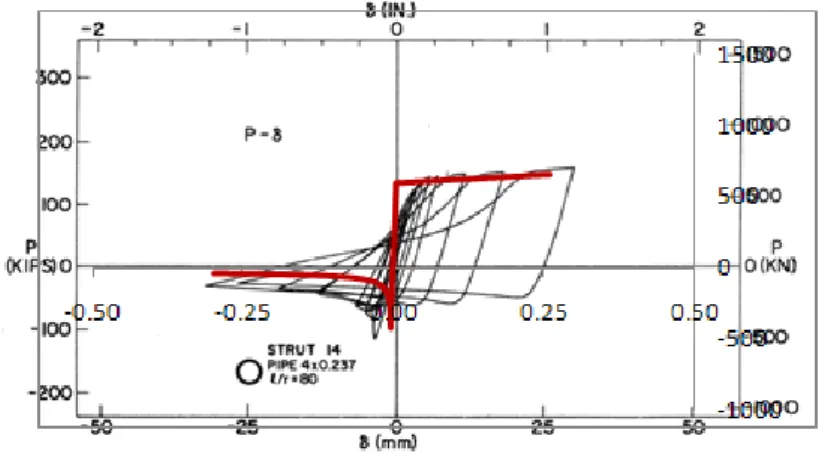
Figure 3.7 - Initial and secant stiffness characterization of hysteretic response (adapted from Priestley et al., 2007)
Earthquakes induce forces and displacements in structures. For elastic systems these are directly related by system stiffness, but for structures responding inelastically, the relationship is complex, being dependent on both the current displacement, and in the history of displacements during seismic response.
The assumption that the elastic characterization of the structure is the best indicator of inelastic performance, as implied by force-based design is in itself clearly of doubtful validity. With RC structures, the initial elastic stiffness will never be valid after yield occurs, since stiffness degrades due to crushing of concrete, Bauschinger softening of reinforcing steel and damage on crack surfaces.
29 In recent years, researchers developed expressions to substitute real multi-storey buildings to a single degree of freedom based on the approximation that the first mode of vibration is dominant. Based on this observation, Priestley et al. (2007) proposed a direct displacement-based design (DDBD) procedure which aimed at an explicit definition of the base shear strength required to achieve a selected seismic performance objective.
The main steps involved in the direct displacement-based design procedure are represented in Figure 3.8.
Figure 3.8 - Fundamentals of direct displacement-based design
In this design procedure, some parameters related to the structure need to be quantified. Firstly, it is necessary to substitute the multi-degree-of-freedom (MDOF) structure to an equivalent single-degree-of-freedom (SDOF) structure. In this process it is necessary to know the mass (mi) and the lateral displacement (Δi) of the structure at each DOF. As a consequence, the definition of the inelastic displacement profile is required. These parameters enable the calculation of the equivalent SDOF system design displacement (Δd) and equivalent mass (me):
30
(4)
(5)
In order to calculate the displacement ductility (μ), it is necessary to calculate the displacement of the SDOF when first significant yielding occurs (Δy). The Equation (4) can also be applied, but this time the displacement characterization should be that corresponding to first yielding.
By knowing the design displacement and the yielding displacement, the displacement ductility is then calculated:
(6)
In order to estimate the equivalent viscous damping (EVD) from the ductility of the system at the maximum response, Priestley et al. (2007) proposed expressions representing the combined effects of elastic and hysteretic energy dissipation within the system.
At this stage, by introducing the design displacement in the inelastic design displacement spectra, the period of the structure is identified and consequently the effective stiffness (Ke) of the equivalent SDOF at maximum displacement.
(7)
Where Ke is the effective stiffness and me is the effective mass, Te is the effective period. The design lateral force, which is also the design base shear force is thus:
(8)
Where Vbase is the design base shear and is the equivalent SDOF system design displacement.
The base shear is then distributed over the high of the structure as lateral inertia forces, and the structure is analyzed under these forces to determine the design moments at locations of potential plastic hinges [Priestley et al. 2007].
31
3.4. S
EISMIC
A
SSESSMENT
One of the most widespread procedures for the assessment of building behaviour due to the action of earthquakes is the Capacity Spectrum Method (CSM). The CSM was firstly introduced in the 1970s as a rapid evaluation procedure in a pilot project for assessing seismic vulnerability of buildings at the Puget Sound Naval Shipyard (Freeman et al., 1975). The CSM is a nonlinear static analysis method, which compares the global force-displacement capacity curve of a structure (pushover) with an earthquake response spectrum in a graphical shape (Freeman, 1998). For this, both the capacity curve and the response spectra have to be converted into a spectral acceleration Sa vs spectral displacement Sd graph. Due to this transformation, the structure is reduced to an equivalent SDOF-structure, responding in its fundamental mode. In this way, supply (pushover curve) can be directly compared to the seismic demand (capacity spectra). In the scope of this procedure the capacity curve, which describes the ability of a building to resist an earthquake, will be superimposed with a response spectra, which represents the demand of an earthquake. Considering the ductility of the building, an intersection point can be determined and the response of the building, in terms of spectral displacement, can be evaluated.
Figure 3.9 - Capacity spectrum method (adapted from ATC-40 by Varum (2003))
By determining the performance point, where this capacity spectrum “breaks through” the earthquake demand, engineers can develop an estimate of the spectral acceleration, displacement, and damage that may occur for specific structure responding to a given earthquake.
The Figure 3.10 shows how the addition of brace systems can improve the behaviour of a structure. In this case the original structure has a performance point close to the ultimate

![Figure 2.18 - Bracing system in the shorter-external bay: device details and general layout [Varum (2003)]](https://thumb-eu.123doks.com/thumbv2/123dok_br/18531194.904610/34.892.154.718.816.1076/figure-bracing-shorter-external-device-details-general-layout.webp)
![Figure 3.1 - Shape of the elastic response spectrum defined in EC8 [CEN, 2005]](https://thumb-eu.123doks.com/thumbv2/123dok_br/18531194.904610/37.892.277.620.424.695/figure-shape-elastic-response-spectrum-defined-ec-cen.webp)