Antenna Design for Underwater
Applications
Oluyomi Aboderin
Doctoral Program in Telecommunications
Supervisor: Prof. H. M. Salgado
Second Supervisor: Dr. L. M. Pessoa
Oluyomi Aboderin
Doctoral Program in Telecommunications
A investigação no campo das comunicações subaquáticas continua a gerar bastante interesse em todo o mundo, devido à ampla gama de aplicações que esta tecnologia cobre, que incluem: monitorização de campos de petróleo e gás no mar, proteção e vigilância costeira, recolha de dados oceanográficos que necessitam de troca de dados entre dois ou mais Veículos Submarinos Autónomos (AUVs) e observação ambiental subaquática para exploração. A este respeito, a tecnologia de ondas de rádio subaquáticas é proposta como um meio de fornecer comunicações de alta velocidade a uma curta distância entre dois corpos subaquáticos. Isto será de grande importância para mergulhadores, fotógrafos subaquáticos ou cinegrafistas, mergulhadores científicos e outros exploradores subaquáticos. No entanto, esta tecnologia sofre bastante com a atenuação em ambientes subaquáticos. Consequentemente, neste trabalho foram consideradas principalmente frequências mais baixas na banda de alta frequência onde o efeito da atenuação é mínimo. Logo, com base em cálculos matemáticos e considerações para a condutividade e permitividade do meio, foram desenvolvidas antenas subaquáticas para uso em ambientes aquosos. As antenas desenvolvidas podem ser agrupadas em relação à sua largura de banda e às suas características de radiação. Nestas incluem-se antenas de banda estreita, banda dupla e de banda larga, bem como aquelas com características de radiação omnidirecional, bidirecional e direcional. Finalmente, os ganhos obtidos com as antenas subaquáticas para sistemas de comunicações subaquáticas são também apresentados.
Este trabalho de investigação pode ser resumidamente dividido em quatro categorias, que são: investigação de análises teóricas relevantes de propagação de ondas de rádio em meios com perdas, extensa simulação computacional usando o software de simulação eletromagnética FEKO, fabrico de antenas com resultados positivos e validação experimental do trabalho realizado, que inclui a medição das características de radiação das antenas no meio.
Assim, a fabricação das antenas projetadas com bons resultados foi realizada nas instalações do INESC TEC. Além disso, as antenas fabricadas foram caracterizadas com o auxílio do analisador de quadripolos recorrendo a uma tanque de água doce localizada no INESC TEC, com as antenas a uma profundidade de 2.5 m da superfície e colocadas no centro do tanque (que tem dimensões de 10 m x 6 m x 5.5 m e a condutividade da água foi de 0.0487 S/m a 25oC).
Research in the field of underwater communications continues to generate a lot of interest worldwide, due to a wide range of applications that this technology covers, which include: offshore oil and gas field monitoring, coastline protection and surveillance, oceanographic data collection which will require data exchange between two or more Autonomous Underwater Vehicles (AUVs) and underwater environmental observation for exploration. In this regard, underwater radio waves technology is proposed as a means to deliver high-speed communications at a short range between two underwater bodies. This will be of great importance to scuba divers, underwater photographers or videographers, scientific divers and other underwater explorers. Though this technology suffers greatly from attenuation in the underwater environment. Consequently this work has been considered mainly in lower frequencies in the high-frequency band where the attenuation effect is minimal.
Therefore, based on mathematical calculations and considerations for the conductivity and permittivity of the medium, underwater antennas were developed in this work for usage in aqueous environments. The developed antennas can be grouped into two with respect to bandwidth and their radiation characteristics. These includes narrow, dual and wideband antennas as well as those with omnidirectional, bi-directional and directional radiation characteristics. Finally, realized gains of underwater antennas for underwater communication systems are as well presented.
This research work can be summarily divided into four categories, which are: investigation of relevant theoretical analyses of radio waves propagation in lossy medium, extensive computer simulation using FEKO electromagnetic simulation software, fabrication of antennas and experimental validation of the work done, which include measurement of radiation characteristics of the antennas in the medium.
Hence, fabrication of the designs with good results was performed in the INESC TEC facilities. Also the manufactured antennas were measured with the aid of Vector Network Analyzer (VNA) and these were carried out in a freshwater tank located at INESC TEC, with the antennas at a depth of 2.5 m from the surface and placed on the centre of the tank (which has dimensions of 10 m × 6 m × 5.5 m and the conductivity of water was 0.0487 S/m at 25◦C).
My foremost gratitude goes to the Almighty God, the creator of Heaven and Earth, for the gift of life and the grace I receive from him prior to the start of the research work till date. I am also very grateful to my supervisor Prof. Henrique Salgado and my co-supervisor Dr. Luís Pessoa for their combined effort, support, guidance and time spent on my research work and in every means that they have assisted me during my program. I am also deeply indebted to Dr. Mario Pereira for his untiring effort to assist all through when we were together in our laboratory. Not forgetting everyone in our -1 floor (Hugo, Joana, Erick and Ricardo), who have assisted in one way or the other and staff of the Robotic units in FEUP and INESC TEC building in ISEP.
I am extremely grateful to the Director General and Chief Executive and the Management Staff of the National Space Research and Development Agency (NASRDA) for granting the study leave that enabled my participation in the MAP-tele doctoral degree program. I am also not ungrateful to friends that were very helpful at the various junction in the course of my studies in Portugal. I will specifically mention; Dr. Abayomi Otebolaku and his family, Dr. Isiaka Alimi and his family, a friend more than a brother. Not forgetting fellow NASRDA colleagues and the entire Nigerian friends that made Portugal be home away from home.
This page will be incomplete without appreciating the members of my family. I am grateful to my parents, Rev. Dr. Ezekiel Olajide Aboderin and Mrs. Esther Olufunmilayo Aboderin, who provided the platform for my educational journey and set me on the right path, I need to say without you guys, there won’t be me. I am as well very grateful to my second Mummy, Mrs. Busola Akinbaani for her unflinching support and prayer all through my journey here. I am also thankful to all my siblings and their family members for their efforts and encouragement throughout my academic pursuit till date. I will like to specifically mention Oluwaseun and Samuel the children of my late sister.
Finally, I am grateful to my best friend, my wife, my "Real Mummy" and my "girl", Ololade Omolola Aboderin for her patience and support both when she was alone with the kids in Nigeria and many time she was alone with them here in Porto. I am also indebted to my "Super Heroes" Inioluwa and Olaoluwa who could not understand why Daddy cannot enjoy weekends, holidays and even anniversaries with them at home in Nigeria and even here in Porto. I salute you guys!! Not forgetting Morayooluwa Olivia, a "master cum Ph.D. graduate", who joined the family during the period that my wife and I were both students in FEUP.
Lastly, to every other individual that have been of assistance in one way or the other during this program, I say THANK YOU.
1 Introduction 1
1.1 Motivation . . . 2
1.2 Aims and Objectives . . . 2
1.2.1 Objectives . . . 3
1.3 Thesis Organization . . . 3
1.4 Contributions . . . 4
1.5 Publications . . . 4
2 Review of Underwater Antennas: Designs, Developments and Usage 7 2.1 Introduction . . . 7
2.2 Antenna in Communication Systems . . . 8
2.2.1 Brief History of Antennas . . . 9
2.2.2 Antenna Sizes . . . 10 2.2.3 Frequency Bands . . . 11 2.3 Types of Antennas . . . 11 2.3.1 Wire Antennas . . . 13 2.3.2 Aperture Antennas . . . 13 2.3.3 Microstrip Antennas . . . 14 2.3.4 Antenna Arrays . . . 14 2.3.5 Reflector Antennas . . . 15 2.3.6 Lens Antennas . . . 15 2.4 Underwater Technologies . . . 17
2.4.1 Underwater Acoustic Communications . . . 18
2.4.2 Underwater Optical Communications . . . 18
2.4.3 Underwater Radio Frequency Communications . . . 19
2.5 Underwater Antennas: Design, Development and Usage in Literatures . . 21
2.5.1 Antenna Developments for Usage in Sea Water . . . 21
2.5.2 Antenna Developments for Usage in Fresh Water . . . 46
2.6 Conclusion . . . 54
3 Propagation of Electromagnetic Waves in Lossless and Lossy Media 55 3.1 Introduction . . . 55
3.2 Maxwell Equations . . . 56
3.2.1 Wave Equations . . . 57
3.2.2 Plane Waves in Lossless (Non-Conducting) Media . . . 59
3.2.3 Plane Waves in Lossy (Conducting) Media . . . 60
3.3 Impairments of Lossy Media on Wave Propagation . . . 62
3.3.1 Water properties . . . 62
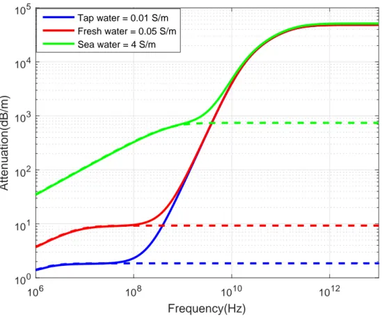
3.3.2 Attenuation . . . 62
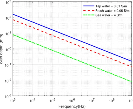
3.3.3 Skin depth . . . 65
3.3.4 Refraction or Interface Losses . . . 66
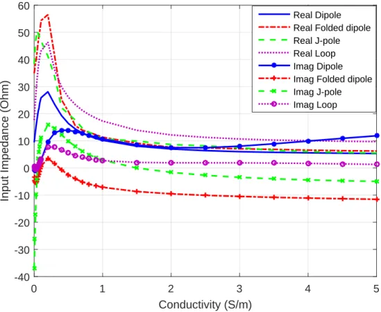
3.3.5 Intrinsic Impedance . . . 66
3.4 Radiation Theory . . . 68
3.5 Field Region of an Antenna . . . 72
3.5.1 Reactive Near Fields . . . 73
3.5.2 Radiative Near Fields or Fresnel Region . . . 74
3.5.3 Farfields or Fraunhofer Region . . . 74
3.6 Conclusion . . . 76
4 Design and Analyses of Narrow band Underwater Antennas 77 4.1 Introduction . . . 77
4.2 Simulation Software . . . 77
4.2.1 HFSS . . . 78
4.2.2 FEKO . . . 78
4.3 Analyses of Underwater Antennas . . . 78
4.3.1 Brief Introduction of the Antennas . . . 79
4.3.2 Designing Antenna Models . . . 81
4.4 Bandwidth and Directivity of Underwater Antennas . . . 90
4.4.1 Performance Evaluation of the Dipole, Folded Dipole and Loop Antennas . . . 90
4.4.2 J-pole Antenna Configurations . . . 94
4.5 Modified Antennas for Installation on the Body of an AUV . . . 105
4.6 Conclusion . . . 114
5 Dual band and Wide band Underwater Antennas 115 5.1 Introduction . . . 115
5.2 Dual band Dipole and J-pole Antennas . . . 115
5.3 Analyses Dual band Dipole . . . 117
5.3.1 Simulation and Experimental Results . . . 118
5.4 Dipole antenna with parasitic element . . . 120
5.4.1 Simulation Results . . . 123
5.4.2 Experimental Results . . . 127
5.5 Loop Antenna with Ground Reflector . . . 128
5.5.1 Simulation Results . . . 133
5.5.2 Experimental Results . . . 137
5.6 ¡VAMOS! Project . . . 143
5.6.1 Antennas for ¡VAMOS! Project . . . 143
5.6.2 Design Methods of the Antennas . . . 144
5.6.3 Confirmation of the Achievable Data Rates of ¡VAMOS! Antennas150 5.7 Friis Equation for Underwater Antennas . . . 151
5.7.1 Realized Gains of Underwater Antennas . . . 152
6 Conclusions and Future Works 157
6.1 Introduction . . . 157
6.2 Conclusion . . . 157
6.3 Future Work . . . 158
6.3.1 Miniaturized Underwater Antenna . . . 158
6.3.2 Highly Directional Antenna . . . 158
A BALUN 161 A.1 Definition . . . 161
A.2 Balun in Underwater Antennas . . . 161
2.1 Antenna operation between the transmitter and the receiver [13] . . . 8
2.2 Hertz experiment of 1887 [17] . . . 10
2.3 Examples of wire antennas . . . 13
2.4 Different sizes of horn antennas [22] . . . 14
2.5 Four-element microstrip antenna array operating at 15 GHz band . . . 15
2.6 Nigerian Communication Satellite ground receiving antennas [24] . . . . 16
2.7 Configurations of lens antennas [13] . . . 17
2.8 Insulated wired antenna on Submarine [37] . . . 22
2.9 Antenna inside iron pipe on Submarine [37] . . . 23
2.10 Long wire antenna trailing Submarine [37] . . . 23
2.11 Loop antenna fixed on Submarine [38,39] . . . 24
2.12 Refraction of radio wave at the surface of water [39,49] . . . 25
2.13 Polyfoam rafts supporting antennas with electronics systems as developed and used by the authors [66] . . . 29
2.14 General overview of Project Sanguine [70] . . . 30
2.15 The proposed project Sanguine by U.S. Navy [39] . . . 30
2.16 BCA antennas [71] . . . 32
2.17 Air-Water Interface transmission in fresh water at 1.8 MHz through two submerged antennas [83] . . . 35
2.18 Communication between submarine and Nevada site [92] . . . 37
2.19 Standalone transmitting and receiving loop antenna [94] . . . 38
2.20 HI-Q antenna [95] . . . 39
2.21 Connectivity between BCAA and submarine through fiber optic [101] . . 41
2.22 Proposed buoyant cable antenna array [101] . . . 42
2.23 Proposed transmitting and receiving wire antennas [106] . . . 43
2.24 Attenuation measurements in fresh water at VHF band [112] . . . 48
2.25 Apparatus for Smith’s experiments [115] . . . 49
2.26 Side view of Dielectric Resonator antenna [118] . . . 50
2.27 Angle-view of proposed Bow-tie patch antenna [124] . . . 51
2.28 Underwater Small loop antenna in a water container [127] . . . 52
3.1 Behavior of σ /ωε as a function of frequency in fresh and sea water [139] 63 3.2 Attenuation coefficient of an electromagnetic wave propagating in water with different conductivity . . . 64
3.3 Skin depth as a function of frequency for tap, fresh and sea water . . . 65
3.4 Refraction losses as a function of frequency for tap, fresh and sea water . 67
3.5 Intrinsic impedance as a function of conductivity . . . 68
3.6 Block diagram for solving antenna radiation [13,39,143] . . . 69
3.7 Geometrical arrangement showing the associated fields of an Hertzian dipole [8] . . . 71
3.8 Antenna’s Field Regions [13,143] . . . 73
3.9 Near-Field (reactive near field and radiative near field) and Far-Field of an antenna[13,144] . . . 75
4.1 Antenna geometry . . . 80
4.2 Feko model of the antennas . . . 82
4.3 Simulations results for change in antenna materials . . . 84
4.4 Resonance frequency as a function of conductivity . . . 85
4.5 Input impedance as a function of conductivity . . . 86
4.6 Resonance frequency as a function of coating thickness . . . 87
4.7 Real part input impedance as a function of coating thickness . . . 87
4.8 Antenna inside air-filled casing . . . 88
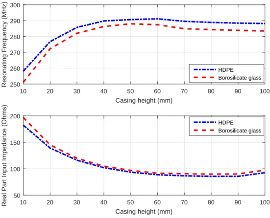
4.9 Resonating frequency and input impedance as a function of casing size . . 89
4.10 Reflection coefficient as a function frequency for the three antennas in fresh water . . . 91
4.11 3D radiation pattern of the antennas in fresh water . . . 92
4.12 2D radiation pattern for the three antennas . . . 93
4.13 Reflection coefficient as a function frequency for the three antennas in sea water . . . 94
4.14 3D radiation pattern of the antennas in sea water . . . 94
4.15 (a) J-pole (b) Super J-pole (c) Collinear J-pole antennas . . . 95
4.16 (a) J-pole (b) Super J-pole (c) Collinear J-pole antennas . . . 96
4.17 Reflection coefficient against frequency for the three antennas operating in freshwater . . . 97
4.18 Modified Reflection coefficient against frequency for the antennas in fresh water . . . 98
4.19 Circuits showing capacitors added to cancel inductive load for the antennas 99 4.20 Reflection coefficient for the J-pole antenna configurations in seawater . 100 4.21 Matching circuit for the antennas in sea water . . . 101
4.22 Radiation pattern of the antennas in sea water . . . 102
4.23 Protractor used in measurement of radiation pattern in freshwater . . . 103
4.24 Fabricated J-pole and super J-pole antennas . . . 104
4.25 Measurement setup showing the antennas inside the pool . . . 104
4.26 Reflection coefficient for the J-pole antenna . . . 105
4.27 Reflection coefficient for the super J-pole antenna . . . 106
4.28 Radiation pattern for the Jpole antenna . . . 107
4.29 Radiation pattern for the super J-pole antenna . . . 108
4.30 Prototype of MARES Autonomous Underwater Vehicle [153] . . . 109
4.31 Prototype of TriMARES Autonomous Underwater Vehicle [154] . . . 109
4.32 Model of Autonomous Underwater Vehicle . . . 110
4.33 Antennas placed outside the body of AUV model . . . 111
4.35 Radiation pattern for the antennas with AUV model . . . 113
5.1 Dual band dipole antenna . . . 116
5.2 Dual band J-pole antenna . . . 116
5.3 Dual band Dipole and J-pole antenna . . . 117
5.4 Input impedance as a function of spacing between antenna arms . . . 118
5.5 Mismatch loss as a function of spacing between antenna arms . . . 119
5.6 Measurement set-up for dual band dipole antenna . . . 119
5.7 Fabricated dual band dipole antenna . . . 120
5.8 Reflection coefficient against resonance frequency for dual band dipole antenna . . . 120
5.9 2D radiation pattern for dual band dipole antenna at 30 MHz . . . 121
5.10 2D radiation pattern for dual band dipole antenna at 60 MHz . . . 122
5.11 Dipole antennas with parasitic elements . . . 124
5.12 Reflection coefficient against frequency for the two antennas . . . 125
5.13 Radiation pattern of the antennas in E-plane at 25 MHz . . . 125
5.14 Radiation pattern of the antennas in E-plane at 40 MHz . . . 126
5.15 Radiation pattern of the antennas in H-plane at 25 MHz . . . 126
5.16 Radiation pattern of the antennas in H-plane at 40 MHz . . . 127
5.17 S21as a function the distance between two antennas for both DipP and DipH128 5.18 Photographs of the DipP antenna after fabrication and during measurement129 5.19 Simulation versus measurement for the DipP Antenna . . . 130
5.20 Simulation versus measurement of the 2-D radiation pattern at 25 MHz . 131 5.21 Simulation versus measurement of the 2-D radiation pattern at 40 MHz . 132 5.22 The antennas placed horizontally to circular ground planes . . . 133
5.23 The antennas placed horizontally to square ground planes . . . 133
5.24 Reflection coefficient against frequency for the antennas on circular ground plane . . . 135
5.25 Reflection coefficient against frequency for the antennas on square ground plane . . . 135
5.26 Directivity against frequency for the antennas . . . 136
5.27 3D radiation pattern of the antenna at 50 MHz, 60 MHz, and 70 MHz respectively . . . 136
5.28 Manufactured square loop antenna with square ground plane . . . 137
5.29 Set up for the measurements . . . 138
5.30 Simulation versus Measurement Square Loop Antenna with Reflector . . 139
5.31 Radiation pattern of the antenna at 50 MHz (a) E-plane, (b) H-plane . . . 140
5.32 Radiation pattern of the antenna at 60 MHz (a) E-plane, (b) H-plane . . . 141
5.33 Radiation pattern of the antenna at 70 MHz (a) E-plane, (b) H-plane . . . 142
5.34 Prototype of communication unit for ¡VAMOS! project . . . 143
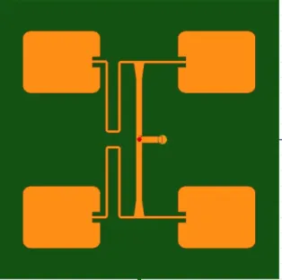
5.35 Isometric view of double helical antenna . . . 144
5.36 Antennas inside frame with ground reflector without epoxy . . . 146
5.37 Antennas covered by epoxy inside frame with ground reflector . . . 146
5.38 Reflection coefficient against frequency for the antennas without epoxy . 147 5.39 Reflection coefficient against frequency for the antennas with epoxy . . . 148
5.41 Radiation pattern of the antennas in H-plane . . . 149
5.42 Fabricated dipole antenna for the project . . . 149
5.43 Fabricated loop antenna for the project . . . 150
5.44 Gain against frequency for dipole antenna . . . 153
5.45 Gain against frequency for dipole antenna with parasitic element . . . 154
5.46 Gain against frequency for J-pole antenna . . . 155
5.47 Gain against frequency for collinear J-pole antenna . . . 155
2.1 ITU’s table of frequency bands [18,21] . . . 12
2.2 Comparison between three underwater technologies . . . 20
2.3 Antennas for underwater communications in sea water . . . 44
2.4 Antennas for underwater communications in fresh water . . . 53
3.1 Field Quantities . . . 55
3.2 Universal constants . . . 55
3.3 Attenuation values at different frequencies for tap, fresh and sea water . . 65
3.4 Field regions of half-wave dipole antenna in fresh water . . . 76
4.1 Typical values of the major water properties @ 25◦C . . . 79
4.2 Dimension of the antennas . . . 83
4.3 Simulation results of the antennas in fresh Water . . . 90
4.4 Simulation Results of the Antennas in sea Water . . . 92
4.5 Dimension of the J-pole antenna configurations in freshwater . . . 97
4.6 Simulation results of the antennas in fresh water . . . 98
4.7 Dimension of the J-pole antenna configurations in seawater . . . 100
4.8 Simulation results of the J-pole antenna configurations in Sea Water . . . 101
4.9 MARES main characteristics [153] . . . 106
4.10 Simulation Results for the modified Antennas with AUV models . . . 110
5.1 Dimension of the Antennas . . . 123
5.2 Dimension of loop antenna with ground reflector . . . 130
5.3 Directivities of the antennas versus operating frequencies . . . 134
AUV Autonomous underwater vehicles BCA Buoyant cable antenna
CDMA Code Division Multiple Access CSA Cavity-backed Slot Antenna
DARPA Defence Advanced Research Projects Agency DRA Dielectric Resonator Antenna
EHF Extremely High Frequency EFL Electric Field Line
ELF Extremely Low Frequency EM Electromagnetic
FEUP Faculty of Engineering University of Porto GPS Global Positioning Systems
GO Geometrical Optics
GSM Global System for mobile communications GTD Geometrical Theory of Diffraction
H2020 Horizon 2020
HDPE High-density polyethylene HF High Frequency
HED Horizontal Electric Dipole HMD Horizontal Magnetic Dipole
IEEE Institute of Electrical and Electronics Engineers
INESCTEC Institute for Systems and Computer Engineering, Technology and Science IOT Internet of Things
ISI Inter Symbol Interference LEO Low Earth Orbit
LF Low Frequency
LORAN-C long range navigation-C LOS line-of-sight
LTE Long term Evolution MF Medium Frequency MFL Magnetic Field Loop
MMIC Monolithic Microwaves Integrated Circuit OC Optical Communication
PEC Perfect Electric Conductor PCS Personal Communication Service
RADAR Radio Detection and Ranging RF Radio Frequency
RFID Radio Frequency Identification ROV Remotely Operated Vehicles RR Radio Regulations
SEAFARER Surface ELF Antenna For Addressing REmotely-deployed Receivers SI International Standard
SINR Signal to Interference plus Noise Ratio SLF Super Low Frequency
SNR Signal to noise ratio
SQUID Superconducting Quantum Interference Device SHF Super High Frequency
THF Terahertz High Frequency TWA Traveling Wave Antenna UHF Ultra High Frequency ULF Ultra Low Frequency
UMTS Universal Mobile Telecommunications System URFC Underwater Radio Frequency Communication UTD Uniform Theory of Diffraction
UWB Ultrawideband
VAMOS Viable Alternative Mine Operating System VED Vertical Electric Dipole
VEIN velocity induced electrode noise VHF Very High Frequency
VLF Very Low Frequency VMD Vertical Magnetic Dipole WI-FI Wireless Fidelity
WiMAX Worldwide Interoperability for Microwave Access WLAN Wireless Local Area Network
WRC World radiocommunication Conference WWW World Wide Web
Introduction
Transmission and reception of signals in aqueous environments require intense study and understanding of various parameters that can cause impairments or degradation thereby altering the propagation phenomenon of signals and devices immersed in it. There has also been an increasing demand for high-speed wireless communication links for underwater applications, which include: oceanographic data collection which will require data exchange between two or more Autonomous Underwater Vehicles (AUVs) and other underwater sensors, coastline protection and surveillance, underwater environmental observation for exploration and off-shore oil and gas field monitoring. In these applications, communications require downloading of mission data from the AUV to the docking station, successful docking of the AUV at the station for recharging through wireless power transfer [1], exchange of data between AUVs and underwater wireless sensor nodes.
In underwater communication there are three established technologies through which underwater communications have been considered, they are; acoustics and ultrasonic signals, optical signals, and radio frequency (RF) signal [2]. Due to the various advantages of the technologies, each of these is most appropriate for different underwater applications. For instance, when long-range propagation (up to tens of kilometers) in fresh or sea water is of paramount concern, as seen in the case of submarines, which are submerged in hundreds of meters below the water surface and communicating with a location on the earth surface, acoustic and ultrasonic systems are the most appropriate technology [3,4,5]. Similarly, when the distance is considerably long and high data-rates with low latency is expected, optical communication systems remain the best technology [4,5, 6]. On the other hand, for a short-range and relatively high-speed communication, which is important for real-time voice, video and data exchange, EM signals will ensure smooth communication in this regards [2]. Despite these advantages, each of the
technologies still has its disadvantages. The acoustic and ultrasonic signal is unfit for real-time and broadband underwater wireless sensor networks because of poor immunity to noise, low data-rates, and high channel latency. In like manner, optical communication requires very good alignment and are as well affected by suspended particles in water and marine fouling. The major disadvantage of EM signals is attenuation, which imposes limits on its usage for underwater communications, as it increases with increasing operating frequency [7,8]. Thus, the main concern of this thesis is to present the design, simulation, construction and measurements of underwater antennas, which will be utmost useful in various underwater applications by scuba divers, oceanographers, underwater photographers, and underwater miners. The performance of these antennas is accessed in fresh water for maximum directivity which is important for propagation distance and bandwidths for the data rates at this distance.
1.1
Motivation
The motivation for this work is to improve short-range communications which may exist between transmitting/receiving devices on scuba divers on one hand and with underwater elements (AUV, ROV (Remotely Operated Vehicles), sensor nodes) on the other hand or between an AUV and docking station, through the usage of underwater radio frequency communications. Robotic based activities in the underwater environment required sufficient bandwidth, improved propagation distance, and minimal attenuation, for real-time transmission and reception of signals in the medium. Hence, what measure(s) can be taken to ensure that the system suffers minimal attenuation? How also can propagation distance be improved for the underwater antennas in the environment? Also, to provide a better alternative to the usage of acoustic communication in the underwater scenario and for the possibility of combining this technology with either acoustic or optical communications in a hybrid underwater network for improved long-range communications in deep water scenario.
1.2
Aims and Objectives
To improve communications between underwater users and equipment through underwater radio frequency communications (URFC), the objective of this work is the design of antennas for underwater communications, followed by fabrication of these antennas, test and measurement.
1.2.1
Objectives
• To develop portable underwater antennas suitable for installation on AUV for onward communication with underwater sensor nodes and docking station;
• To develop underwater antennas useful for scuba divers for data harvesting in the shallow water scenario;
• To develop an analytical method that can be used to determine the gain of these antennas, which will assist in analyzing their performance in a lossy medium; • To validate these analytical methods through practical measurements of the
underwater antennas;
1.3
Thesis Organization
Beside this introductory chapter, four other chapters and the concluding remarks were added thereafter.
Chapter 2 addresses the review of underwater antennas with respect to designs, developments, and usage. This chapter comprises:
• definitions of antennas, brief history, and types.
• Underwater technologies with a table showing similarities and differences of the technologies;
• Extensive review of the state of the art with respect to antenna design and EM propagation in underwater environments, spanning around a century.
In chapter 3, the propagation of electromagnetic waves in lossless and lossy media is presented. This includes theoretical information regarding propagation in water, determination of the radiation characteristics of antennas submerged in lossy medium and also factors that affect RF propagation in the medium.
In chapter4, full analyses of underwater antennas regarding the effect of the change in materials of the wire, the coating of the wire of the designed antennas, change in conductivity of the medium and when the antennas are placed in an air-filled casing were presented. In the second part, the performance of designed narrow band antennas was also presented.
In chapter 5, the performance of antennas with dual and wideband capabilities are assessed with respect to their radiation characteristics and bandwidth. Also presented in
this chapter are the antennas designed in a European project that our team partnered with. Though these antennas were originally designed as wideband, in order to ensure that the antennas were secured against water waves in the medium, addition of materials with different permittivities and their final performance is further investigated. Final in this chapter, realized gain and link budget of underwater antennas is presented.
Chapter6 is the final chapter of this thesis, where final conclusion is drawn and the future works were also presented.
1.4
Contributions
The main contributions of this research are summarized below
• Model approach to the usage of wire antennas for narrow, dual and wideband communication in the underwater environment;
• Designing of underwater antennas at a specified resonating frequency;
• Modeling of directional underwater antennas for improved propagation distance; • Underwater antenna modeling around the body of Autonomous Underwater
vehicles;
• Experimental measurements of the radiation pattern of underwater antennas; • Determination of realized gains of underwater antennas;
1.5
Publications
The following publications are the results of these contributions:
1. S. I. Inacio, M. R. Pereira, H. M. Santos, L. M. Pessoa, F. B. Teixeira, M. J. Lopes, O. Aboderin and H. M. Salgado, "Antenna design for underwater radio communications" OCEANS, Shanghai China, 2016;
2. S. I. Inacio, M. R. Pereira, H. M. Santos, L. M. Pessoa, F. B. Teixeira, M. J. Lopes, O. Aboderin and H. M. Salgado, "Dipole Antenna for Underwater Radio Communication" Underwater Communications Network (UComms), Lerici Italy, 2016;
3. L. M. Pessoa, M. R. Pereira, O. Aboderin, H. M. Salgado, and S. I. Inácio, “Antenna for underwater radio communications,” patent ep 3 291 364A1;
4. O. Aboderin, S. I. Inacio, H. M. Santos, M. R. Pereira, L. M. Pessoa and H. M. Salgado, "Analysis of J-Pole Antenna Configurations for Underwater Communications" OCEAN, Monterey California, United States of America, 2016; 5. O. Aboderin and L. M. Pessoa and H. M. Salgado, "Performance evaluation of
antennas for underwater applications" Wireless Days 2017, Porto Portugal;
6. O. Aboderin, L. M. Pessoa and H. M. Salgado, "Analysis of loop antenna with ground plane for underwater communications," OCEANS 2017 - Aberdeen, Aberdeen, 2017;
7. O. Aboderin, L. M. Pessoa and H. M. Salgado, "Wideband dipole antennas with parasitic elements for underwater communications" OCEANS 2017 - Aberdeen, Aberdeen, 2017;
8. O. Aboderin and L. M. Pessoa and H. M. Salgado, "Analysis of Antennas Designed for Fresh Water Applications" to be submitted to IEEE Access;
9. O. Aboderin and L. M. Pessoa and H. M. Salgado, "A Survey of Underwater Antennas: Designs, Developments and Applications" To be submitted to IEEE Communications Surveys & Tutorials.
Review of Underwater Antennas:
Designs, Developments and Usage
2.1
Introduction
The much breakthrough in modern-day scientific research and technology can be attributed to the military exploits mostly around the first and second world wars. Some of the technologies that benefited from military activities include the antenna designs and development, satellite communication, Internet network, underwater communications among others [9]. Antenna, therefore, has proven to be an integral part of other technologies as the reliant on its usage cuts across different applications in space science, terrestrial networks, and underwater communications. In space science, antenna remains one of the most important equipment that ensures respective transmission and reception of telecommand and telemetry data, to and from satellites launched into orbits that is thousands of kilometers away from the earth’s surface. Similarly, terrestrial networks has witnessed evolution from; wired to wireless, copper wire to fiber optic where long-distance transmission and interference which are limited to the former are well resolved in the latter, analog to digital, which include metamorphosing from first generation (1G) to the most recent fifth generation (5G) networks, whilst still looking ahead to the sixth generation (6G) [10, 11]. The need for high-speed, short-range communication for relevant applications in the context of underwater exploration and mining makes the development of various antennas that are capable of meeting these requirements of great importance to scuba divers, underwater miners, and other users. Therefore, this chapter begins discussing antenna as a whole with respect to its definition, history and types. Also, major technologies that ensure smooth communications in the underwater environment are compared and extensive review of designing, developing and
usage of underwater antennas over many decades and for many services is finally given.
2.2
Antenna in Communication Systems
One of the most critical components importantly needed in the communication systems (mobile, wired and wireless) in any medium is an antenna. The increasing need of improving communication mechanism; in household equipment (including television antennas (loop or Yagi), multi-functional cell phones, hand-held portable devices, long-range communications, electronic chips (including Radio Frequency Identification (RFIDs)) and most recently Internet of Things (IoT) has made the entire globe to depend on antennas for day-to-day activities. In actual fact, antennas in their millions are so ubiquitous worldwide.
Many definitions have been used to describe an antenna in several pieces of literature, but in all, it involves radiating and receiving of radio waves. For instance, it is defined in IEEE Standard Definitions of terms for antennas as "a means of radiating or receiving electromagnetic (radio) waves [12]." Webster’s dictionary also defines an antenna as a metallic device, which may be rod or wire for radiating or receiving radio waves. Several writers in books and articles also have their respective definition for an antenna. Balanis in [13] defined it as transitional equipment or device between free space and a guiding device, whilst in [14] it is defined as a transducer that converts a guided wave to a free space wave or vice-versa and is also defined as a device that converts bounded circuit field into propagating electromagnetic wave (Transmitting antenna) and by reciprocity is a device that collects power from passing electromagnetic waves (receiving antenna) [15]. Thus, in all these definitions, it is obvious that an antenna is a device for transmitting and/or receiving radio waves or electromagnetic waves. The basic description of an antenna in either transmitting or receiving form is presented in Fig.2.1.
Electromagnetic wave Antenna Transmitter Transmission Line Antenna Receiver Transmission Line
Figure 2.1: Antenna operation between the transmitter and the receiver [13]
Apart from the antenna, the medium where the antenna will be operated is also critical in the design analysis of such antennas. For instance, if an antenna is designed for usage in the air at a certain operating frequency, there will be frequency shift, when the same
antenna is encased in a glass or plastic box, due to change in its surrounding medium. There will be further shifting in the operating frequency when the antenna is immersed in water, which is also depending on whether it is fresh or sea water. All these frequency shifts depend on change in the permittivity and conductivity of the surrounding medium of the antenna.
2.2.1
Brief History of Antennas
James Clerk Maxwell’s unified of the theories of electricity and magnetism into the electromagnetic theory in 1883, which was presented in a set of relations known as Maxwell’s equations which forms the basic foundation for modern-day communication technologies. Four years later, Prof. Henrich Rudolf Hertz (1857-1894), (the SI (International Standard) unit of frequency is named after him) performed experiments to demonstrate the existence of electromagnetic radiation. This was done by connecting a dipole antenna to a variable voltage source as the transmitter and using a loop antenna as the receiver. A prototype of Hertz’s experiment is presented in Fig. 2.2. The experiment confirmed that information can be transmitted between two locations through electromagnetic waves. Another important early contribution came from Guglielmo Marconi. He developed and commercialized wireless communication through the introduction of a radiotelegraph system. He was renown for the first Atlantic transmission in 1901 from Podhu, in the United Kingdom to St. John, Newfoundland in Canada, by employing un-tuned systems. His transmitting antenna is made up of 50 vertical wires, which were made to resemble fan and were connected to ground through a spark transmitter and the receiving antenna was a 200 m wire, is supported by a kite. It is important to note that Marconi used monopole antennas for most of his experiments, such that vertical monopole antennas are being referred to as Marconi antenna [16,13,17].
From Marconi’s remarkable long range transmission up till the 1940s, other efforts in antenna development were restricted to usage of wires as radiating elements and operating at frequency up to Ultra High Frequency (UHF) bands. During World War (II), more antenna types like apertures, horns and reflector antennas were developed to cater for the need at that time. These resulted in the development of broadband, circularly polarized and other antennas for numerous applications. From the 1960s till date, advances were made in computer technology, mobile communications, wired and wireless communications among others, which also impacted positively in antenna developments for radio broadcasting, wireless communications (terrestrial, satellite and underwater) and RADAR (Radio Detection and Ranging) systems. Also, proliferation of emerging standards and applications (Global System for mobile communications
Variable Voltage Source
Figure 2.2: Hertz experiment of 1887 [17]
(GSM), Universal Mobile Telecommunications System (UMTS), Code Division Multiple Access (CDMA), Bluetooth, infrared, Personal Communication Service (PCS), Wireless Local Area Network (WLAN), Long term Evolution (LTE), Wireless Fidelity (WI-FI), Worldwide Interoperability for Microwave Access (WiMAX) and most recently Internet of Things (IoT)) require antennas that will match their service requirements, with respect to bandwidth (narrowband, wideband, ultrawideband (UWB)), high gain, directivity (omnidirectional and direction) and high efficiency.
2.2.2
Antenna Sizes
Antenna dimensions are usually expressed in terms of the wavelength (λ ). It can be said that the frequency, wavelength, and size are related such that as the frequency decreases, the wavelength increases and the sizes increases. Thus for effective radiation of a named antenna, it is critical for its length to be a fraction of wavelength. Most common of these are half-wavelength (λ /2) and quarter-wavelength (λ /4). Hence, the length of a half-wave dipole antenna is approximately λ /2, whereas the length of the conductor for a monopole antenna is λ /4. Therefore the idea of antenna miniaturization is to ensure that a named antenna has its physical dimension shrink without any degradation on its performance nor affect the initial operating frequency, noting that a small antenna will always have to consider its size with respect to the operation wavelength [13]. In the underwater
environment, it is important to design an antenna that operates in the frequency band where attenuation effect is minimal, which should be below 400 MHz, as discussed later in section 3.3. Though it is expected that such an antenna might have a large physical dimension given the operation frequency (λ = vf in air) and the wavelength in free space equals 0.75 m. But in the underwater environment, the wavelength changes, which is due to the effect of permittivity (water relative permittivity is 81) and conductivity (0.005 S/m in fresh water and 4 S/m in sea water) in this medium and subsequently the dimension of the antenna. For instance, if a dipole antenna is designed to operate at 300 MHz; in the air, the wavelength is 1 m, whereas, at the same frequency, the wavelength is 0.124 m and 0.077m in fresh and sea water respectively.
2.2.3
Frequency Bands
Operating frequency is very important in any form of communication worldwide. It plays a significant role in the designing of equipment and providing services accordingly. It is fundamental in the design and developments of antennas for any services. To this end the International Telecommunication Union (ITU), an agency of the United Nation (UN) tasked with the responsibility of allocation, allotting, and management of frequency bands, which in conjunction with the International Union of Radio Science (URSI) designated the bands appropriately. It is therefore important for communication equipment manufacturers, antenna designers, network managers among others to be conversant with these allocations for proper design and management of equipment. In antenna design, for instance, the frequency of operation, as well as conductivity and permittivity, are important for determining the dimension of antennas depending on whether the medium is lossy or lossless. Thus, Table 2.1 gives details of the band designations as defined by the ITU in the radio regulations (RR), these documents contain four sub-documents (Articles, Appendices, Resolutions, and Recommendations) and the information therein are subject to review every four years during the World Radiocommunication Conference (WRC) [10,18,19,20].
2.3
Types of Antennas
Antennas come in different forms (types, shapes, and configurations). This is depending on its usage, application and integration with other electronic devices. Thus, it can be grouped either by their physical structures or by various antenna parameters. For instance;
Table 2.1: ITU’s table of frequency bands [18,21] Band
Number Band Name Symbols
Frequency range Metric subdivision 1 Extremely Low Frequency ELF 3 - 30 Hz 2 Super Low Frequency SLF 30 - 300 Hz 3 Ultra Low Frequency ULF 300 - 3000 Hz 4 Very Low Frequency VLF 3 - 30 kHz Myriametric waves 5 Low Frequency LF 30 -300 kHz Kilometric waves 6 Medium Frequency MF 300 -3000 kHz Hectometric waves 7 High Frequency HF 3 - 30 MHz Decametric waves 8 Very High Frequency VHF 30 - 300 MHz Metric waves 9 Ultra High Frequency UHF 300 - 3000 MHz Decimetric waves 10 Super High Frequency SHF 3 - 30 GHz Centimetric waves 11 Extremely High Frequency EHF 30 - 300 GHz Millimetric waves 12 Terahertz High Frequency THF 300 - 3000 GHz Decimillimetric waves
• if grouped with respect to bandwidth, they can be either narrowband or broadband (wideband, ultra-wideband (UWB));
• if organized with respect to their polarization, they can be circular, linearly (horizontal and vertical) or elliptically polarized;
• if divided with respect to their resonance, they can be traveling wave or resonant antennas;
• if classified with respect to the number of elements, they can be element antennas or antenna arrays.
2.3.1
Wire Antennas
Wire antennas are ubiquitous and seem to be more common than other antenna types and it is very familiar to a layman as they can be seen virtually everywhere. They are low cost, easy to construct and made from conducting wires. These antennas are used in automobiles, personal communications/applications, spacecraft, ships, and buildings. Various shapes of these antenna types include; Dipole, loop, Helix, J-pole, and spiral. Each of these may take different shapes, through which their performance can be optimized [17, 13]. Example of wire antennas are presented in Fig. 2.3. These antennas have been explored in the context of this thesis for underwater applications and are discussed in chapter 4. It is important to note that wire antennas are more suitable to use in the underwater environment, as it can go directly into the medium, without the need protect the antennas from water, unlike printed antennas that will require spraying of Epoxy resin on its either side, which will, therefore, alter the design frequency.
(a) Loop antenna (b) Dipole antenna
(c) J-pole antenna
Figure 2.3: Examples of wire antennas
2.3.2
Aperture Antennas
These are antenna types with a physical opening that allows transmission and reception of electromagnetic waves. Aperture antennas can be flush-mounted, which made them suitable for use in spacecraft and aircraft. Example of antennas in this category includes;
horn antenna, a slot antenna, inverted-F antenna, and slotted waveguide antenna. Horns antennas are presented in Fig.2.4 comprises of pyramidal (rectangular) and conical (circular) shapes.
Figure 2.4: Different sizes of horn antennas [22]
2.3.3
Microstrip Antennas
Microstrip antennas consist of a metallic patch which can come in different shapes (circular, square, triangular), the substrate and the metallic ground plane. They are basically conformable to planar and non planar surfaces, low profile, simple or easy to design, low cost, when mounted on rigid surface they are mechanically robust, compatible with Monolithic Microwaves Integrated Circuit (MMIC) and as well very versatile with respect to their polarization, pattern, resonant frequency and impedance.
2.3.4
Antenna Arrays
Antenna arrays are sets of identical antennas that are radiating individually and are arranged in an electrical or geometrical form, in order to improve the overall performance over a single element antenna. It is also known as Phased arrays, which are used typically for military radar applications and in adaptive cruise control. The pattern of the array is determined by the relative amplitude and phase of the excitation fields of each source and the geometric spacing of the sources. Other antenna types like microstrip, wire, reflector antennas can form elements of an array antenna as seen Fig.2.5, where four elements microstrip antenna operating at 15 GHz, were used to form an array. Some of the advantages of this antenna include [23,13];
• increase the overall gain;
• improve Signal to Interference plus Noise Ratio (SINR);
• improve or reduce radiation characteristics in a particular direction(s); • "Steer" the array to ensure that it is most sensitive in a particular direction; • deduces the route of the incoming signals.
Figure 2.5: Four-element microstrip antenna array operating at 15 GHz band
2.3.5
Reflector Antennas
These are antennas with typically high gain (30 - 40 dBi), with a prospect to communicate over great distances, for radio communications, radio astronomy high-resolution radars and others. In principles, reflector antennas operate on the theory known as geometrical optics (GO). They are used in satellite communications and other outer space-related communications, where signals travel several thousands of kilometers between the transmitters and the receivers (satellite and ground receiving station). Fig. 2.6 shows the reflector antennas at the ground receiving center of the Nigerian Communication satellite in Abuja, Nigeria.
2.3.6
Lens Antennas
They are used primarily to collimate divergent energy and prevent it from radiating in an unwanted direction. This is achieved by proper shaping of the geometrical configuration
Figure 2.6: Nigerian Communication Satellite ground receiving antennas [24]
in addition to the choice of appropriate material of the lenses. This antenna can convert various form of divergent signals into plane waves. Typical configurations of lens antennas are given in Fig. 2.7.
(a) Lens antennas with refractive index of n>1
(b) Lens antennas with refractive index of n<1
Figure 2.7: Configurations of lens antennas [13]
2.4
Underwater Technologies
In underwater communications, there are three established technologies through which transmissions in this medium have been considered, they are [2]:
1. Underwater acoustic communications; 2. Underwater optical communications and 3. Underwater radio frequency communications.
Each of these has its merits and demerits in their usage for various applications in the medium. It is widely known that acoustic waves can propagate at a long range up to 20 km but at the expense of relatively low data rates, which can be around 1 b/s [2,25]. Optical
communications, on the other hand, provide high data rates up to 1 Gbps, at seemingly propagation distance of about 100 m. On the other hand, wireless propagation of, the radio waves can achieve up to 1 km range with 100 b/s, but the data rates continue to decrease as the propagation distance increases. These three technologies are examined extensively and are presented as follows.
2.4.1
Underwater Acoustic Communications
Acoustic waves technology has been widely embraced worldwide as a viable solution for underwater communication because of its ability to establish long-distance links (up to tens of kilometers). Also, it is characterized by having low attenuation and can even operate in the absence of line-of-sight (LOS) between the terminals and in deep water [26, 27]. Despite these advantages, there are many disadvantages such as low data rates (propagates up to 20 Km at almost 1 b/s), high channel round trip delay (channel latency), poor immunity to noise and a high cost of nodes that have led to continuous research in alternative technologies. They are also not robust since they are easily affected by temperature, ambient noise, turbidity, and pressure gradients. Furthermore, they are dangerous to marine life and the ecosystem. Also, they offer poor propagation in shallow water due to interference [28]. The acoustic signals can also experience Inter-Symbol Interference (ISI), due to the multipath propagation effect [28]. In addition, this technology has low propagation velocity, when compared with other technologies, consequently, it suffers greatly from Doppler effects [29]. Thus, acoustic receivers often employ adaptive equalization [28, 30]. The ambient noise in acoustic communications is frequency dependent, which can be traced to a number of sources. For instance, at frequencies below 100 Hz, the noise is mainly due to marine traffic, whereas wind and rain are significantly responsible for noise at higher frequencies around 100 kHz, the noise level is dependent on the intensity of rain and wind. At frequencies beyond this, thermal noise, whose spectral density increases with frequency, is involved [28]. Despite these disadvantages, the technology is still being used around the world but other technologies are also gaining acceptance because of their advantages over acoustic systems.
2.4.2
Underwater Optical Communications
Apart from acoustic communications, another technology that has been widely used in the underwater environment is Optical Communication (OC). OC is as an alternative technology that provides ultra-high data rates up to the Gigabit per second (Gbps) and about 10-150 Mbps over moderate propagation distances (10-100 meters) [31]. It is
also immune to transmission round-trip delay, which is an advantage over acoustic communications. Likewise, it offers guaranteed signal fidelity (secured link) and low power consumption, among other things. However, this technology can only be used for short-range communications because of the strong backscatter from suspended particles and severe water absorption at the optical frequency band [32]. It also requires good alignment or line of sight for its propagation. Apart from these, optical waves are difficult to use for cross communications from seawater to air and vice versa, and they are also affected by scattering and absorption. They can also propagate at moderate link range (up to tens of meters) [31].
2.4.3
Underwater Radio Frequency Communications
The third technology, which can also be used for underwater communications is based on Electromagnetic (EM) waves in the radio frequency (RF) range. Usage of RF in the underwater environment began as a dream in the middle of the twentieth century, but further experiments have shown that when RF signal is coupled with digital signal compression, it has greater advantages than other technologies in the underwater scenario [25]. Apart from these, radio signals allow flexibility in the deployment of a wireless sensor network for coastal monitoring applications. This is nearly impossible with other technologies because of the high level of aeration and sediments present in coastal water. In water, EM waves propagate at a velocity that is about 4 times faster than that of the acoustic waves. This implies that Doppler shift and propagation delay or latency are significantly reduced and subsequently this technology is suitable for real-time data transfer [3,26,4,5,33].
Besides, it has also been proven that RF waves are less sensitive to reflection and refraction in shallow waters than the acoustic waves. This helps in reducing the multipath effect. In addition, the nature of water (dirty or clean) and suspended particles have very little or no impact on the RF waves. Also, it has no known effects on marine lives [34]. Furthermore, using the same technology, AUVs and ROVs can be charged at underwater docking station through wireless power transfer [1]. In terms of alignment, RF waves do not require strong alignment or LOS for propagating in any medium and are immune to acoustic noise. It also has the capability for cross-boundary transmission, that is water-to-air transmission or vice versa. This ensures long-range communication for the RF wave. In addition, out of the aforementioned technologies, it is the least affected by tidal waves or water turbulence [35,25]. Moreover, RF waves do not require mechanical tunning, which is required with the acoustic communications and neither does it require surface repeaters especially when interfacing the water-air boundary [25, 6].
The similarities and differences including advantages and disadvantages of the three technologies are presented in Table2.2.
Table 2.2: Comparison between three underwater technologies Parameters Acoustics communications Optical communications EM/RF communications Data rates Low data
rates in kbps High data rates in Gbps Moderate data rates in Mbps Latency
(roundtrip delay) High latency Moderate latency Low latency Shallow water
affected by multi-path Propagation
Not affected Not affected Propagation
speed Low High High
Propagation
Distance Long range Short range Short range Water condition
(Turbidity and suspended particles) affected by water condition affected by water condition not affected
Attenuation Low Low
High, which increases with frequency and water salinity Cost High cost of
nodes High cost
Relatively low cost
Line of
2.5
Underwater Antennas: Design, Development and
Usage in Literatures
Antenna developments for underwater applications have been in the literature for more than a century. These developments have been considered in fresh and sea waters, with respect to the operations and usages in each medium. To this end, antenna design, developments and usage in sea water and fresh water are as presented in the subsections.
2.5.1
Antenna Developments for Usage in Sea Water
One of the earliest published work in an underwater antenna was by G. H. Clark in 1909. His experiment consisted of, two wires of 9.2 m long which were connected to the transmitting apparatus located at the Navy Yard Norfolk and also two insulated wires of 5.2 m long submerged below the surface of water at the depth of 1.2 m located at the Navy Yard Washington were connected to the receiving apparatus through a condenser of capacity 0.003 microfarad. Signals were received by the receiver, which was around 19 km away from the transmitter [36]. In furtherance of the work, experiments were also conducted on a boat located near Norfolk. Here, copper plates were attached to the insulated wires; while one plate was suspended over the stern into the water, the other was suspended over the bow into the water. Signals transmitted from the Navy Yard in Norfolk were received on this boat at a distance of up to 24 km. Despite the crude nature by which these experiments were conducted, it nonetheless became a remarkable achievement in the history of underwater antenna communication [36]. J. H. Rogers similarly transmitted from boat with underwater wires to a station in his home in 1916 [36]. About three years after, Rogers produced what can be tagged resounding breakthrough in the usage of antennas for underwater application, which was written by H. W. Secor and titled "American Greatest War Invention". The inventor based his idea on what should be a logical relationship between wireless transmission and reception of radio signals in the surface to those in the underwater environment. He believed that, since an antenna can transmit signal from a high altitude platform (mast) to a receiving antenna at a designated distance, then the same signal is transmitted appropriately through water, can be received by a receiving antenna submerged in underwater. In his work, he first used a heavily insulated stranded cable, stretched from stem to stern and attached to the submarines as a receiving antenna as presented in Fig.2.8. This was later replaced by an insulated antenna placed in iron pipes located inside the submarines, probably to protect the antenna from the effect of the medium as shown in Fig.2.9. The third is a long wire antenna attached to the last compartment of the submarine, thereby trailing it as presented in Fig. 2.10.
Based on these analyses and a couple of experiments, a wireless communication link was established with the submarines placed in seawater. This invention became an important tool that the American Navy used during the world war and the system he built paved ways for research in the usage of antennas in underwater environments. It was also reported that the submarines must be at a distance of less than 10 km to the transmitting antenna in seawater due to its conductive nature, whereas in fresh water the receiving antenna can be at any depth [37].
Rec
app
Insulated wire Rec app Grd´d on Hull Grd´d on HullFigure 2.8: Insulated wired antenna on Submarine [37]
Shortly after Rogers’s invention, Willoughby and Lowell also in the same year, performed further experiments on the detection of submarines. They discovered that loop antennas can likewise detect or receive radio signals transmitted through water [38, 39, 40]. The antenna system comprises of an insulated phosphorus bronze wire which was used to construct a single loop antenna that was firmly grounded by the hull of the submarine. This simply means hulls were part of the antenna and the prototype of their design is as presented in Fig. 2.11. The duo claimed that they were able to successfully establish communication links between two submarines, which were entirely submerged in seawater 20 Km apart at a wavelength of 952 m [38]. Though the communication distance between the two submarines was later disputed by V. R. Fisher [41], it was obvious that the loop antenna was similarly used to established communication in seawater between two submarines. Around the same time frame, Major General George O. Squier conducted experiments where he used an insulated wire for transmission of high-frequency signals through the water. His experiments confirmed
Iron pipe Iron pipe Rec app
Figure 2.9: Antenna inside iron pipe on Submarine [37]
The trailing submarine ´´Aerial´´
Figure 2.10: Long wire antenna trailing Submarine [37]
that EM waves can be transmitted through wires that were submerged in water [42]. Also, a US. Navy Lieutenant-Commander Taylor conducted experiments on underground and underwater antennas. He used a long wire of about 153 m long at a navy station in Washington and a submarine base [40,39].
Figure 2.11: Loop antenna fixed on Submarine [38,39]
Moore in 1951, was the first individual to present an electromagnetic theory of underwater antennas. This form the fulcrum of his doctoral program. Also between 1951 and 1957, James R. Wait conducted a series of studies on insulated loop, finite wire, magnetic dipole and Hertzian dipole antennas that were operating in conducting medium. Further tests were specifically conducted on Hertzian dipole by placing it perpendicular to the surface and immersing it in sea water. He concluded that the antenna radiation suffers attenuation of up to 20 dB when compared with the radiation on the surface at the operating frequency of 30 kHz and the antenna lowered to about 30 m in the medium [43, 44, 45, 46, 47]. Similarly in 1953, in the report submitted to the University of California by Banos and Wesley, mathematical solution to determine the electromagnetic field components generated by a horizontal electric dipole antenna was presented. In addition, four suitable integrals for the cartesian components of the Hertzian vectors and the cylindircal components of the field vextors (~E and ~H) were obtained [48]. In [49] the author examined the performance of small antennas operating at the VLF band in terms of signal reception when mounted on the submarine and submerged in a lossy medium. This was demonstrated by using the sketch in Fig. 2.12, where it can be seen that the signal is tilted downward and a fraction of the power radiated into the water. In this regard, the conductivity of the water play an important role in determining the index of refraction of the medium, consequently, the signal propagation is nearly vertical. Also, the propagated signal is greatly attenuated due to the effect of skin depth (this parameter will be discussed fully later) which affects conductors. Performance and characteristics of antennas submerged in the lossy medium were presented by Weeks and Fenwick in [50]. Mathematical expressions were derived for the input impedance, efficiency, current
distribution, and field strength of the horizontal dipole and vertical monopole antennas in the medium. The authors concluded that Signal to noise ratio (SNR) of horizontal dipole antennas doubled that of the vertical monopole when both are submerged in seawater, regardless of their respective depth in the medium.
Water Air
l/(2p) (e0m0)
(sm0)
d
Figure 2.12: Refraction of radio wave at the surface of water [39,49]
In 1959, Navy Research Laboratory developed an omnidirectional cross-loop antenna shortly after World war II. This antenna that operated in the VLF band, was embedded in plastics and mounted on a retractable mast [40, 51]. The antenna was part of the general overview of the loop antennas used in submarines communications that Turner gave en-route his own discovery. Other loop antennas presented in the paper operated at HF and UHF bands. However, his proposed solution is a hybrid antenna that worked at combined HF-UHF-IFF bands [51]. W. L. Anderson and R. K. Moore in 1960 calculated theoretically the energy density spectra of the transient electromagnetic fields at various distances between the field source and the medium. The source and the media are the magnetic dipole and seawater respectively. They concluded that as the distance increases to the critical value, the frequency on the other hand slowly shifts downward. Consequently, the electric and magnetic fields also decrease and are approximated as r−2 and r−3respectively [52].
Moore and Blair also used dipole antennas in their studies of the problem associated with communication between antennas placed in a conducting medium like sea water. Expressions were presented for the fields of the horizontal and vertical dipole as well as electric and magnetic dipole antennas. It was concluded that the field of the horizontal dipole is stronger than that of the vertical dipole, due to the vertical nulls in the fields radiated from it [53]. In 1962, cross-boundary (water to air or vice versa) transmission became a subject of interest to the military. This was done by establishing
a communication link between a helicopter in the air and a submarine submerged in seawater. Here, vertical electric dipole (VED) antenna operating at 10 kHz in the air and a horizontal electric dipole (HED) antenna operating at 100 kHz in the sea were proposed. These two antennas were proposed based on their respective field strength in each medium. It was also presented that difference in their respective operating frequency is due to differences in the properties of the two media [54]. In 1963 Hansen presented analyses of three antennas namely; loop and dipole in insulating radomes and an insulated long wire antenna with end electrodes, in a lossy medium based on their merit factor. Relative gain is the main merit factor considered as it relates vertically polarized power per unit solid angle to the total input power. From the analyses, the relative gain factor of the long wire antenna in the medium is better than the other two antennas, as this antenna acts basically to feed current into the electrodes, which subsequently set up a vertical quadripole of the conduction current. [55]. In the same year, King and Iizuka analyzed electric and magnetic fields of a half-wave dipole antenna submerged in a homogeneous isotropic dissipative medium, in terms of their admittances and currents. The studies compared E and H-fields obtained from the theoretical analyses with those from the measurements. General formula was derived for the fields components (near and far) around the antenna. Similarly, experimental results obtained for the field components validated the theoretical as both results are in good agreement [56]. Still, in 1963, Hasserjian and Guy performed a series of experiments to validate the theoretical approximations for subsurface antennas in a lossy medium. Experimental results of the horizontal dipole antenna in a lossy medium and the theoretical approximation agrees well [57]. It was still in that same year that Fenwick and Weeks theoretical and experimental analyses and characteristics of antennas placed in a lossy medium. Dipole antennas (center fed, end fed grounded and center fed ground) were used in these analyses. Based on the results obtained for the input impedance and current distribution of the antennas, relative communication efficiency (RCE) of the submerged antennas is defined. Subsequently, the authors presented a table of RCE for common antennas and theoretical and experimental results of the field strength of the antennas are in good agreement [58]. Apart from his work on the electromagnetic theory of underwater antennas, Roland K. Moore also theoretically analyzed the performance of antennas on the surface and in a conducting medium. The antenna gain and its radiation pattern were the two parameters considered in these analyses. Also, biconical loop and two forms of straight wire antennas operating at VLF were used in the work. It was shown that there is no significant difference among the gains of the three antennas in the medium, as it is related to current (uniform or reduced) and their respective wavelength. The conclusion was that calculation of power radiated and radiation resistance of antenna submerged
![Figure 2.12: Refraction of radio wave at the surface of water [39, 49]](https://thumb-eu.123doks.com/thumbv2/123dok_br/19203951.955049/49.892.154.786.271.541/figure-refraction-radio-wave-surface-water.webp)
![Figure 2.13: Polyfoam rafts supporting antennas with electronics systems as developed and used by the authors [66]](https://thumb-eu.123doks.com/thumbv2/123dok_br/19203951.955049/53.892.154.781.157.659/figure-polyfoam-supporting-antennas-electronics-systems-developed-authors.webp)
![Figure 2.17: Air-Water Interface transmission in fresh water at 1.8 MHz through two submerged antennas [83]](https://thumb-eu.123doks.com/thumbv2/123dok_br/19203951.955049/59.892.162.780.167.415/figure-water-interface-transmission-fresh-water-submerged-antennas.webp)
![Figure 3.1: Behavior of σ /ω ε as a function of frequency in fresh and sea water [139]](https://thumb-eu.123doks.com/thumbv2/123dok_br/19203951.955049/87.892.171.741.176.655/figure-behavior-σ-function-frequency-fresh-sea-water.webp)