Repositório ISCTE-IUL
Deposited in Repositório ISCTE-IUL: 2019-04-29Deposited version: Publisher Version
Peer-review status of attached file: Peer-reviewed
Citation for published item:
Brandão, F. J. S. & Paio, A. (2019). Context-aware mass customization construction system: methods for user captured as-built plans. In Matthias Hank Haeusler; Marc Aurel Schnabel; Tomohiro Fukuda (Ed.), Intelligent and informed: proceedings of the 24th International Conference on Computer-Aided Architectural Design Research in Asia. (pp. 101-110). Wellington: Victoria University of Wellington. Further information on publisher's website:
http://papers.cumincad.org/cgi-bin/works/Show?caadria2019_195 Publisher's copyright statement:
This is the peer reviewed version of the following article: Brandão, F. J. S. & Paio, A. (2019). Context-aware mass customization construction system: methods for user captured as-built plans. In Matthias Hank Haeusler; Marc Aurel Schnabel; Tomohiro Fukuda (Ed.), Intelligent and informed: proceedings of the 24th International Conference on Computer-Aided Architectural Design Research in Asia. (pp. 101-110). Wellington: Victoria University of Wellington.. This article may be used for non-commercial purposes in accordance with the Publisher's Terms and Conditions for self-archiving.
Use policy
Creative Commons CC BY 4.0
The full-text may be used and/or reproduced, and given to third parties in any format or medium, without prior permission or charge, for personal research or study, educational, or not-for-profit purposes provided that:
• a full bibliographic reference is made to the original source • a link is made to the metadata record in the Repository • the full-text is not changed in any way
The full-text must not be sold in any format or medium without the formal permission of the copyright holders. Serviços de Informação e Documentação, Instituto Universitário de Lisboa (ISCTE-IUL)
Av. das Forças Armadas, Edifício II, 1649-026 Lisboa Portugal Phone: +(351) 217 903 024 | e-mail: [email protected]
SYSTEM
Methods for user captured as-built plans
FILIPE JS BRANDAO1and ALEXANDRA PAIO2 1ISCTE-IUL / ISTAR -IUL
1[email protected] 2ISCTE-IUL / ISTAR-IUL 2[email protected]
Abstract. The problem of context, a fundamental aspect of dealing with built environments, has not been adequately addressed by mass customization systems so far, which has limited their scope of application. The aim of the present article is to evaluate the adequacy of existing methods of producing as-built plans of rooms by non-expert users for the automatic generation and production of partition walls for building renovation. This paper highlights criteria to develop appropriate methods of capturing context for mass customization construction systems.
Keywords. Mass Customization; As-built Plans; Building Renovation; Computational design.
As computational design becomes common in architectural practice, alternate modes of production, such as Mass Customization (MC), arise as viable models for architecture and the building industry (Kolarevic, 2013). MC allows distribution of control between the actors in the construction process, empowering the building owner to make intelligent and informed decisions and take the production closer to his/her context (Davis, 1987).
This paper is part of an ongoing research with the aim of developing a disassemble-able and mass customizable construction system of partition walls for building renovation by building owners. This design-to-production system will generate drawings for fabrication, instructions for assembly, and cost estimation. Therefore, it is necessary to develop the construction system, the generative process for digital design and fabrication and a graphical user interface for building owners to interact. The interface must allow a generic user to manipulate the parametric model and generate solutions for the intended space. To generate a design solution for building renovation, the shape of the space boundaries needs to be input to the design system. In previous research (Brandao et al., 2016), the definition of the boundaries was circumvented by requiring the user to input dimensions of the wall to be designed, height, width and length. This process is less than ideal, as it makes many assumptions on the boundary conditions: that Intelligent & Informed, Proceedings of the 24th International Conference of the Association for
Computer-Aided Architectural Design Research in Asia (CAADRIA) 2019, Volume 2, 101-110. © 2019 and published by the Association for Computer-Aided Architectural Design Research in Asia (CAADRIA), Hong Kong.
the wall will span two existing walls and will go from the floor up to the ceiling; that the angles of the wall to the existing walls are close to perpendicular; that the floor, walls and ceiling are level within a specified tolerance. Also, as the number of generated walls increases, the complexity of the interfaces of the walls with the space boundaries grows, complicating the planning process for the building owner.
Tang et al (2010) reviews several methods of automatic reconstruction of as-built models for BIM from laser-scanned point clouds. Several authors (Bhatla et al., 2012; Tanskanen et al., 2013) have proposed 3D reconstruction pipelines using single lens cameras or smartphones to generate dense 3D models. Lowe et al (2011) proposed an automated method for context capturing and virtual navigation within a game environment. Yet, at the architectural scale, these methods are still out of reach of non-expert users, whose needs are catered for by mobile apps that generate semi-automated as-built 2D parametric plans. In this context, two questions emerge: Are existing methods of capturing or generating floor plans for non-expert users sufficiently accurate to use as a basis for generating walls for digital fabrication? Are non-expert users able to use these methods reliably to produce sufficiently accurate plans?
The present article reviews existing manual and semi-automated methods of capturing the geometry of the space boundaries, both directed at experts and non-experts, with the aim of reflecting on the adequacy of the existing tools and identifying criteria for the development of a semi-automated process of generating as-built models, a more intelligent way for users to capture their context.
1. Methodology
To answer the previous questions two experiments were conducted; the first one by the researchers, using several surveying methods to produce as-built plans of three rooms; and a second experiment where a group of non-expert users and group of expert users were asked to survey one of the rooms using phone application-based methods. In the context of this research, an expert user is a person with professional experience in doing building surveys.
The goals of the first experiment are to gather insights on the accuracy, time and usability of the different methods, and for researchers to become acquainted with the workflow of each app. The second experiment aims to evaluate the usability of the applications by carrying out usability testing (Molich and Dumas, 2008). What errors does the user make while using the selected workflow / method? How accurate are their tape / laser measurements? Is the user aware of the room’s geometrical properties? Was the user capable of using the app(s) to draw a polygon with the correct number of sides? Is the user confident that the result faithfully represents the space and its dimensions? Is the user satisfied?
For the experiments, three rooms in a to-be renovated building were selected and surveyed using expert methods such as photogrammetry (PHG), terrestrial laser scanning (TLS) and manual survey techniques (Manual), and non-expert methods such as existing mobile phone applications. The selected rooms are in a XIX century building in the historical city centre of Braga in Portugal. It
SYSTEM
is a common building typology with stone façades and party walls, wooden floors and roofs, located in a narrow plot. It is part of a 4-building complex which is due to be renovated. The rooms were selected for the challenges they present to surveying, but also because they represent the typical situations that are encountered in building renovation in Portugal, particularly in XIX century buildings. Identified challenges are high geometric complexity: such as rooms with more than 4 sides, without right angle corners, uneven walls, floors or ceilings, rooms cluttered with furniture or objects, challenging wall finishes, such as black painted or high reflective surfaces. All the previously specified characteristics pose problems to the perception of the space by users and are challenging to some surveying methods.
1.1. 1ST EXPERIMENT
The TLS campaign was realized with a FARO FOCUS S120 station, a Leica GPS 1200 GNSS station and a Leica 1203 TCRP total station. It comprised the 4 buildings interiors, backyards, street and backyard façades. The survey took 3 days and produced a point-cloud composed of 258 scans grouped in 23 clusters. A typical interior scan took 2 minutes to complete and an exterior one 8 minutes. To scan Room 1 three scans where needed, Room 2 and 3 required two scans. The point clouds were aligned in SCENE with an average error of 2,36 mm. To compare the results with the remaining methods, horizontal sections of the rooms were then exported in DXF format to AutoCAD and the 2D plans manually designed. A similar workflow was used for the photogrammetry survey. Photographs were taken inside the three selected rooms with a Nikon D700 camera in RAW format, using a 25mm manual focus lens. The images were post-processed in Lightroom, exported to JPEG and imported to PhotoScan, where the point clouds were generated and exported to Cloud Compare to create sections of the point clouds to use for designing the 2D plan of the room. The rooms were also surveyed using manual methods of survey commonly used by architects, comprising paper sketches of the room and measurements taken with laser distance meter or tape measure (Figure 1). These measurements and sketches were later used to design the plan in a 2D CAD program.
Two applications available for phones were used to test non-expert surveying methods. At the time of testing, these were highest ranking free apps with a complete feature set for designing room plans on the App Store. Both applications were designed to be used by experts and non-experts alike and provide several different workflows. The first application (App 1) provides 4 workflows for surveying rooms: by capturing the corners using the phone’s camera; designing a square room using the editor; designing a free shape using the editor; design the space using an underlayer plan. The second application (App 2) provides three workflows for producing as-built plans: Scan by touching walls, scan with camera, draw manually. Two workflows where selected that seemed to represent the most common types available across multiple applications. On App 1 the camera method was selected. This first workflow involves using a mix of Augmented Reality, the phone’s camera and orientation sensors and user input to map the room corners, captured in a clockwise or anticlockwise sequence. On App 2 the
workflow of touching walls with the phone was selected. This workflow involves placing the phone against all the walls in clockwise or anti-clockwise sequence, requiring user input only to determine the type of object the phone is placed against, whether a wall, door or window. It uses the phone’s accelerometer and orientation sensors, combined with user movement, to determine the shape and dimensions of the space. Both workflows generate a room plan which the user edit, inputting wall lengths, adding/subtracting corners or walls. Both the automatically generated output and the manually edited plan, with the measurements obtained in the manual method, were recorded and reproduced in CAD for comparison purposes.
Figure 1. Manual on-site survey plans left to right: Room 1, Room 2, Room 3.
1.2. 2ND EXPERIMENT
The second experiment was conducted with a group of 5 non-expert users and 4 expert users, in line with usability tests for an iterative development process (Molich and Dumas, 2008). They were asked to survey Room 1 with mobile phone applications to produce an as-built plan of the existing space. The aim of the survey was not specified to the participants, and they were free to use one or both applications. No limitations on workflow were imposed, consequently, the users had at their disposal all 7 workflows to survey the room. A laser distance meter and a tape measure were provided. None of the users had previously used the applications or has acquainted with similar applications. The process was recorded in video by the researcher, and the user was told terminate the experience when a satisfactory result was achieved. The output of each of the users was recorded and reproduced in 2D CAD.
2. Results
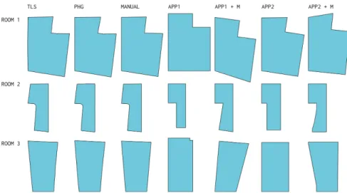
The plans produced in experiment 1 are compared in Figure 2. For the sake of clarity all the windows and doors have been removed and only the inner outline of the space is kept. TLS and PHG output plans contain more detail than the remaining methods. Automated app-based methods are significantly less accurate
SYSTEM
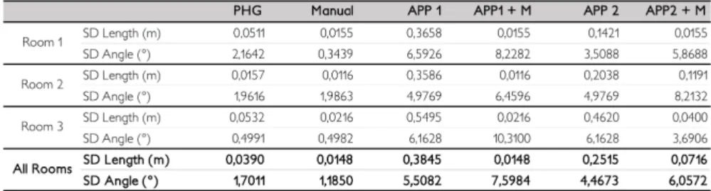
than the expert methods. Introducing onsite measurement to correct the plans does increase the accuracy of the side’s dimensions, as would be expected, but decreases the accuracy of the angles of the polygon (Table 1). It was also noted that the final plan of the Apps workflows (APP 1 + M and APP 2 + M) can vary significantly depending on the side where the introduction of the manual measurements starts.
Figure 2. Matrix of plans by surveying method and room.
Figure 3 presents a comparison of the different outcomes of the workflow of APP 1 plus manual measurements. Taking the output plan of App 1 on Room 1 (Figure 2), the manual measurements were inserted on the application clockwise, beginning on the side marked with the arrow for each of the plans. This workflow produced 5 significantly different plans of the same room.
Figure 3. Outcomes of the workflow App1 + M of the plan of Room 1 by starting side.
The observed behaviour of the applications is: (1) the application automatically locks the user introduced dimensions and scales the remaining unlocked dimensions to maintain the angular properties of the space; (2) The shape of the space is kept constrained to an ortho-polygon until all the lengths of the “third side” are introduced; (3) When the total dimension of a wall where there is a door is changed, the dimension of the door is kept, and the wall’s partial dimensions are changed; (4) The form of the room polygon is the result of the introduced
dimensions; and (5) There is no way to edit the angular dimensions or to add diagonal measurements. Both applications have the issues presented in Figure 3 and similar observed behaviour. App 2 presents a further problem, when the second last side measurement is introduced the last side can be split in multiple segments. This behaviour was observed in Room 2 and 3.
Table 1. Standard Deviation (SD) by room and across all rooms.
For length and angle comparisons between the several outputs, the TLS and PHG output were simplified to a polygon of 4 or 6 sides, depending on the room. The results for Room 1 are presented in Table 1. This process alone demonstrated that important details, that would have impact on fabrication, are not captured. For example, in Room3 a bulge on the wall of 4cm is eliminated. TLS is used as a reference for calculation of the standard deviation (SD). Manual survey process was found to have a smaller SD than PHG. PHG can be severely affected by bad lighting conditions, lack of detail, or reflective objects such as mirrors. The use of a full-frame DSLR improves image quality but the low room lighting required the use of a large aperture, thus decreasing the depth of field. Room 1 presented the highest SD on angle and length measurements amongst the rooms surveyed with PHG (Table 2). This room’s walls and ceiling are half painted in white and half painted in black. The high contrast between white and black walls requires a compromise on exposure because of the high dynamic range of the scene. Using high dynamic range images might improve the quality of the results but this was not tested. Nonetheless, all the expert methods of survey presented much better results than app-based methods.
To compare the consequences of using the produced plans as a basis for planning the subdivision of the space and the production of partitions walls with digital fabrication, several possible subdivisions of Room 1 where considered. For space constrains we present the one that is most likely to happen, Sub 2. In Sub 2, the space is divided in three spaces. A corridor that connects the interior door to the exterior door and serves a room with a en suite bathroom. This is a common trait of the renovation interventions in these building typologies, since many of these XIX century buildings do not have interior bathrooms as is expected in contemporary housing in Portugal. These rooms would naturally require doors but as these are generally within the partition walls, the impact of dimensioning errors of the walls would only affect the doors if these are at the extreme edges of the partitions. To design the subdivision the following rules where used: (1) subdivide the space with a wall parallel to the exiting wall with an offset of 1.42m; and, (2) subdivide the
SYSTEM
larger space by creating a wall parallel to the interior partition wall with an offset of 1,8m. The first rule places the wall between the interior window and door on one side and next to the exterior door on the other. Onsite there are visible remnants of a wall in this position that was demolished at some point. This position is optimal but there is space on both sides to accommodate some rotation. The second rule is meant to create a bathroom with a bathtub, with 1,80x0,8m standard dimensions, a toilet, a wash basin and a bidet. The parallelism of opposing walls should ideally be kept, particularly because of the bathtub, however that it is not mandatory, as it would still be possible to install the standard bathtub if the shortest distance between walls is larger than the length of the bathtub
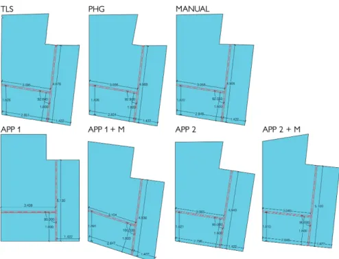
Figure 4. Outcomes of the application of rules of wall generation to each of the plans.
Figure 4 presents the results of the application of the proposed rules to each of the as-built plans. Henceforth, for briefness we will refer to the walls generated by the application of the rules to each as-built plan by the name of the respective method used to survey it. PHG walls are shorter and have an internal angle 0,26 degrees larger than TLS walls. This indicates that no problems would arise in the assembly of the walls on-site due to space constraints. The same is true for the Manual walls, except for the longer wall which is 3 cm longer. Depending on the characteristics of the constructive system used, this could cause fitting problems. In all the remaining cases the differences are larger both in wall lengths and internal angle. Both App1 plans are significantly different in terms of shape. App 1 + M plan in particular might lead the user to change the design rules or select an
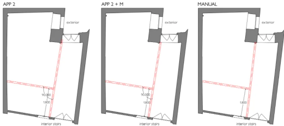
altogether different design solution to avoid spaces with acute angles. Of all the Apps walls, App 2 and App 2 +M are the most similar to the walls generated in the TLS plan. Figure 5 presents the application of the generated walls in the Manual, APP 2 and APP 2 + M as-built plans to the TLS as-built plan. The walls have been positioned aiming to follow the design rules. This was possible with the walls generated over the Manual as-built plan but not with the other two. In both instances, to keep the parallelism of the bathroom wall to the existing wall, the longer wall overlaps the interior window on one side and the exterior door on the other. If on the other hand, the parallelism of the longer wall to the party wall is kept, it would not be possible to install the bathtub. Furthermore, in both cases the longer wall is 6,2 to 22,2 cm longer than the existing space.
Figure 5. Application of walls generated in APP 2, APP 2 + M and Manual plans to TLS plan.
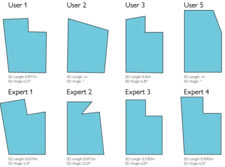
Experience 2 shown that all expert users were able to design a plan of the existing room, but only two non-expert users, User 1 and User 3, were able to design a plan topologically similar to the surveyed room, i.e. a polygon with six sides. Both of these users only tried the capture method in App 1. User 2 tried several methods in App 1, first to manually design the room in the application but could not construct a closed polygon, then to start with a square room but did not find a way of adding the remaining 2 sides. Lastly, User 2 also tried App 2 using the camera method but did not understand there was a need to click the interface to capture the intersection of the walls with floor after recognizing the floor. Instead tried to use the floor recognition method to capture the walls. In the end the user designed two 4-sided rooms because the user could not find a way of designing a six sided one. User 4 used the capture method of App 2 first but faced similar difficulties as User 2 and gave up, then switched to App 1 but gave up without designing any plan. User 5 used App 1 Capture method. Initially did not understand there was a need to click to confirm the corners. On a second try, User 5 realised it was required to point the camera at the intersection of the floor with two walls and to click a button to confirm. When going around the space in sequence user 5 missed one corner. User 5 was not familiar with using a laser measurement tool but quickly managed to understand how measurements are made.
SYSTEM
Despite that, this user was not aware of the need to measure the distances close to the walls, instead measurements were taken at least 1,5m away from the corner. Only the User 1 and 3 were satisfied with the results produced and did not express frustration on using the apps. All the remaining expert or non-expert users felt that the results didn’t match their perception of the space. Experts 1, 2 and 4 doubted the accuracy of the angles generated by the app-based method. Expert 1 and 2 referred the need for triangulations to validate results. Expert 3 understood that results were not accurate but felt these were sufficient for a preliminary assessment, despite that the expert only checked the dimensions of two walls. Several users expressed frustration with the number of steps required before starting to measure the space, particularly with the requirement to add information about the space being measured. Only the experts 1 and 2 shown sufficiently meticulous method on conducting the measurements of the space both with the tape measure or the laser distance meter.
Figure 6. Comparison of user generated plans and respective standard deviations to TLS.
3. Discussion and Conclusions
Results of Experience 1 shown that non-expert methods do not produce accurate plans of non-orthogonal rooms, and while these findings are generally applicable, the design-to-production workflows of MC require higher precision than conventional construction workflows that rely on on-site fabrication. The sample size does not allow us to draw conclusions on average angular errors. Yet, statistical significance is pointless when the app-based methods display the angle control problems this research uncovered. Polygon perimeter is not sufficient to
accurately draw an irregular non-orthogonal polygon. Also, as the wall planning exercise demonstrated, even small angular deviations have a high impact on the partition walls lengths. Although our research only compared two applications, all the applications we are currently aware of share this problem. Nonetheless, these methods require simple inputs from users which makes them an appealing option for MC construction systems. We believe this issue can be overcome with better polygon drawing algorithms that include diagonal measurements, which could be informed with architect’s practical knowledge in surveying building interiors. Directly measuring angles on site is error prone and requires specialized tools. Surveyors circumvent this by measuring diagonals. The process is similar to subdividing a shape into triangles. By measuring all of the sides an accurate position is obtained. In practice, it is hardly ever necessary or possible to measure all diagonals of a space, so a classical triangulation algorithms would be unwarranted, triangulations in this case are a means to close the polygon.
Non-expert users experienced difficulties in using the interfaces and collecting measurements. While some of the usability issues causing the first problem are app specific, both apps need to reduce unnecessary room classification steps, introduce clear and concise stepwise workflow instructions, introduce ways of guiding the user, namely better initial tutorials and contextual interface hints. Also, the interface and workflow should be unobtrusive to allow the user to focus on the room.
MC requires a link between the product variation and the features of the user’s context, physical and social. Thus, a MC system in architecture should offer ways for users to provide the needed contextual information on the physical environment. Tested methods of generating floor plans for non-expert users are not adequate. Future research should focus on ways of improving the accuracy of these methods or introducing automated methods which rely less on user input. In conclusion, better methods of capturing context by building owners are needed to allow the implementation of a MC system of partition walls for building renovation. References
Bhatla, A., Choe, S.Y., Fierro, O. and Leite, F.: 2012, Evaluation of accuracy of as-built 3D modeling from photos taken by handheld digital cameras, Automation in Construction, 28, 116-127.
Brandao, F., Paio, A., Sousa, J.P. and Rato, V.: 2016, Cork Re-Wall: Computational Methods of Automatic Generation and Digital Fabrication of Cork Partition Walls for Building Renovation, Gestão e Tecnologia de Projetos, 11(2), 9-24.
Davis, S.: 1987, Future Perfect, Addison-Wesley, New York.
Kolarevic, B.: 2013, Mass Customization + Non-Standard Modes of ( Re ) Production, ACSA101: New Constelations / New Ecologies.
Molich, R. and Dumas, J.S.: 2008, Comparative usability evaluation (CUE-4), Behaviour & Information Technology, 27(3), 263-281.
Tang, P., Huber, D., Akinci, B., Lipman, R. and Lytle, A.: 2010, Automatic reconstruction of as-built building information models from laser-scanned point clouds: A review of related techniques, Automation in Construction, 19(7), 829-843.
Tanskanen, P., Kolev, K., Meier, L., Camposeco, F., Saurer, O. and Pollefeys, M.: 2013, Live Metric 3D Reconstruction on Mobile Phones, Proceedings of the IEEE International Conference on Computer Vision, Sydney, 65-72.