255 Air isodose curves in a mammography room
Radiol Bras. 2008 Jul/Ago;41(4):255–258 Original Article • Artigo Original
Air isodose curves in a mammography room*
Curvas de isodose no ar em uma sala de mamografiaMaria Cecília Baptista Todeschini Adad1, Gabriela Hoff2, Elaine Evaní Streck2, Rochele Lykawka3
OBJECTIVE: The present study was aimed at evaluating the absorbed dose in air in a medical examination room during a mammography simulation, to re-evaluate the level of patients’ exposure as well as the necessity of radiological protection barriers. MATERIALS AND METHODS: Data regarding absorbed dose in air were collected during mammography simulation with a BR12 breast phantom in a Senograph 600T-Senix HF mammograph. For this purpose, 158 CaSO4 dosimeters were distributed over rectangular grids around the bucky at three different heights. RESULTS: The highest value for absorbed dose in air recorded on the center of the phantom surface and centralized on the primary beam was 8.33 mGy, while the lowest value recorded exclusively due to radiation scattering was 0.008 mGy. CONCLUSION: These results indicate that the utilization of additional shielding in mammography facilities might not be necessary for craniocaudal acquisition, provided the distances considered for the present study are observed. However, the necessity of radiation protection of the patient should be emphasized.
Keywords: Radioprotection; Isodose curves; Mammography.
OBJETIVO: O objetivo deste trabalho foi obter a distribuição da dose absorvida no ar numa sala de mamo-grafia durante a simulação de um exame mamográfico, visando a reavaliar a necessidade do uso de barreiras de proteção radiológica nessas salas e a exposição das pacientes. MATERIAIS E MÉTODOS: Os dados da dose absorvida no ar foram coletados mediante simulação de exame mamográfico de um simulador de mama de BR12, em um equipamento Senograph 600T-Senix HF. Para tal, 158 pastilhas de CaSO4 foram distribu-ídas em malhas retangulares em torno do bucky, em três alturas distintas. RESULTADOS: O valor mais ele-vado da dose absorvida no ar, registrado no ponto central da superfície do simulador, centralizado no feixe primário, foi de 8,33 mGy, enquanto o menor valor registrado, devido exclusivamente ao espalhamento, foi de 0,008 mGy. CONCLUSÃO: Estes resultados indicam que o uso de blindagem adicional nas salas de ma-mografia pode não ser necessário na incidência crânio-caudal, desde que as distâncias consideradas neste trabalho sejam observadas. No entanto, eles enfatizam a necessidade de proteção da paciente.
Unitermos: Radioproteção; Curvas de isodose; Mamografia. Abstract
Resumo
* Study developed at Faculdade de Física da Pontifícia Uni-versidade Católica do Rio Grande do Sul (PUC-RS), Porto Ale-gre, RS, Brazil.
1. Master in Materials Engineering and Technology, Pontifícia Universidade Católica do Rio Grande do Sul (PUC-RS), Porto Ale-gre, RS, Brazil.
2. PhDs, Associate Professors at Pontifícia Universidade Ca-tólica do Rio Grande do Sul (PUC-RS), Porto Alegre, RS, Brazil.
3. Bachelor in Physics, Managing Partner, AFIM – Assessoria em Física Médica Ltda., Porto Alegre, RS, Brasil.
Mailing address: Dra. Gabriela Hoff. Avenida Ipiranga, 6681, Prédio 10, sala 207, Bairro Partenon. Porto Alegre, RS, Brazil, 90619-900. E-mail: [email protected]
Received February 5, 2007. Accepted after revision November 12, 2007.
for protection of the professionals, patients and general public.
Among other studies already developed with similar purposes, the one developed by Vieira et al.(4) has determined isodose
curves in brachytherapy for linear radioac-tive sources; Goulart et al.(5) and Andrade
et al.(6) have estimated isodose curves in a
hemodynamics room(5) for a digital
fluoros-copy equipment besides the room where patients received iodine therapy(6) in
nuclear medicine; and Fanti et al.(1) have
developed a software for simulation of di-agnostic radiography, allowing the con-struction of 3D images reflecting the en-trance surface air kerma in a virtual patient. These data were compared with experimen-tal information obtained by the same team with an anthropomorphic phantom and the aid of thermoluminescent dosimeters.
In the present study, the distribution of absorbed dose in air in a mammography Adad MCBT, Hoff G, Streck EE, Lykawka R. Air isodose curves in a mammography room. Radiol Bras. 2008;41(4):255–258.
The level of radiation exposure of both patient and technical team during mammo-graphic examination is defined by the Portaria (Order) nº 453 issued by the Sani-tary Vigilance Secretariat – Ministry of Health, Brazil, establishing that this expo-sure must be optimized, meaning that this exposure must be reduced to the lowest level possible(3). Additionally, as regards
the patient absorbed dose during a radio-logical evaluation of the breast, this Por-taria (Order) establishes that the skin en-trance dose for a craniocaudal view should not exceed 10.0 mGy in a grid raphy and 4.0 mGy in a gridless mammog-raphy, considering a compressed breast with a thickness of 0.045 m for a screen-film system and a unit with anode and mo-lybdenum filtration(3). These
recommenda-tions reflect the relevance of knowing the radiation scattering in the mammography room during the radiological examination
0100-3984 © Colégio Brasileiro de Radiologia e Diagnóstico por Imagem
INTRODUCTION
Mammography is known as the most ef-fective method for detecting non-palpable breast cancer(1,2), and has been routinely
256
Adad MCBT et al.
Radiol Bras. 2008 Jul/Ago;41(4):255–258 room was experimentally determined
dur-ing the simulation of a mammographic examination, allowing the preparation of a 2D map demonstrating the doses distribu-tion (isodose curves) at three different heights around the bucky, as well as the spatial localization of the sites in the room with higher absorbed dose in air.
It is expected that these data can be use-ful in the planning of radiological protec-tion for patients and professionals involved in the practice of mammography, as well as may shed light on the discussion about the calculation of shielding and utilization of individual protection equipment by the patients. Considering that the normal expo-sure rates for the general public must be restricted so that the effective yearly dose does not exceed 1 mSv(3), and that the limit
for the equivalent level of environmental dose is 5 mSv/year in areas under control and 0.5 mSv/year in non-controlled areas, as far the planning for radiological protec-tion barriers is concerned(3), also it is
nec-essary to discuss the actual necessity of these barriers in mammography room, tak-ing into consideration that the highest ab-sorbed doses were recorded at sites corre-sponding to the organs of the patient.
MATERIALS AND METHODS
Data were collected at SIDI – Medicina por Imagem, Novo Hamburgo, RS, Brazil, in a room were a Senograph 600T Senix HF unit (GE Medical Systems; Buc Cedex, France) was installed. Mammographic ex-aminations were simulated with a non-an-thropomorphic, homogeneous distribution BR-12 breast phantom, representing a breast with 50% fat and 50% glandular tis-sue. Examinations were performed in com-pliance with the protocol and technique routinely utilized in the unit, i.e., Mo-Mo target-filter combination, AT 28 kVp and 77 mAs load.
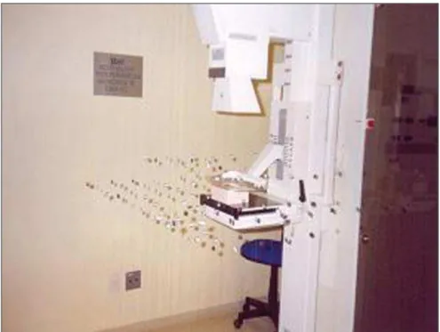
Measurements of absorbed dose in air were performed with 158 CaSO4 dosim-eters duly identified, distributed over three rectangular grids with a 0.10 m horizontal spacing around the bucky, at three differ-ent heights: at the level of the bucky (z = 0.00 m), 0.10 m below the bucky (z = –0.10 m) and 0.10 m above the bucky (z = +0.10 m), as per Figure 1.
The dosimeters were attached with ad-hesive tape to wires hanging from the roof and their positioning coordinates (X, Y, Z) were noted down, so that the recorded dose was correctly associated with the respective positioning.
Aiming at avoiding the interruption of the routine mammography unit operation and higher equipment wearing out, ther-moluminescent dosimeters were selected for allowing the whole data collection in a single experiment, considering that tests performed with an ionization chamber had indicated the necessity of about 10 expo-sures for each point. Additionally, the op-tion was for CaSO4 dosimeters appropriate to the voltage range utilized, without affect-ing the measurements reliability.
After irradiation, the dosimeters were sent for reading by a specialized company, and the graphic representation of data re-garding the distribution of absorbed dose in air around the bucky/phantom was pre-pared with the aid of an images processing software.
RESULTS
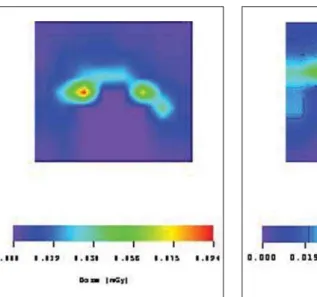
The isodose curves representing the measurements of absorbed dose in air are shown on Figures 2, 3 and 4, respectively
for heights of 0.10 m above the bucky and 0.10 m below the bucky.
The highest value for absorbed dose in air (8.3 ± 0.2) mGy was recorded on the center of the phantom surface (0.00; 0.10; 0.00) m focused by the primary beam. On the other hand, the lowest value for ab-sorbed dose in air (0,008 ± 0.001) mGy was recorded on the most distant site reached by the primary beam (0.24; –0.30; 0.10) m. The Portaria (Order) 453 establishes that the skin entrance dose for a cranio-caudal view should not exceed 10.0 mGy in a grid mammography and 4.0 mGy in a gridless mammography, considering a compressed breast with a thickness of 0.045 m for a screen-film system and a unit with anode and molybdenum filtration(3).
Therefore, considering that the experiment described in the present study was per-formed with the grid, the highest value for absorbed dose in air is within the limits defined by the mentioned Portaria (Order) 453. Additionally, according to the Ameri-can College of Radiology, the procedure recommended for determining the mea-surement of the breast entrance dose is positioning the ionization chamber on the X-ray field beside the breast phantom, at 0.040 m from the chest wall edge on the image receptor, and with the center of the
257 Air isodose curves in a mammography room
Radiol Bras. 2008 Jul/Ago;41(4):255–258 chamber level with the top surface of the phantom(7).
The highest values recorded for ab-sorbed dose in air at the three different heights in relation to the bucky were (0.029 ± 0.001) mGy at (0.10; 0.27; –0.10) m, (0.097 ± 0.003) mGy at (0.14; –0.18; 0.10) m, and (0.094 ± 0.003) mGy at (0.00; – 0.30; 0.0) m.
An extra dosimeter was positioned on the lower surface of the bucky to evaluate its filtration degree. The measurements demonstrated a decrease of > 95% in the phantom entrance dose.
Also, based on data demonstrated on Figures 2, 3 and 4, the authors could ob-serve that, at the most distant sites, the val-ues for accumulated absorbed dose after 10 exposures were bellow the dosimeters sen-sitivity threshold, so being recorded as zero.
DISCUSSION
The data obtained show that, for a 0.41 m distance on the axis X (mammography bucky to the room door) and a 0.33 m dis-tance on the axis Y (mammography bucky to the room walls), the estimated dose originating from the scattered radiation at the level z = 0.00 m corresponds to the background radiation. This evidence al-lows the discussion about the actual neces-sity of utilizing radiological protection
bar-riers in a mammography room exceeding these dimensions. However, a definite de-cision should be based on additional tests with other view angles, projecting the pri-mary beam directly towards the room door or walls. Also, it is necessary to take into consideration the financial cost for install-ing the mentioned barriers and that its project and construction would involve different professionals, including medical-physicists, architects and civil construction workers.
The highest absorbed doses recorded for z = +0,10 m are shown on Figure 3 as red figures, and one of these regions is in front of the mammography unit, where the patients is positioned during the examina-tion. For a woman who is approximately 1.70 tall (a median height), it is estimated that this would be the site of the thyroid gland. Considering that the thyroid is radi-osensitive, periodic long exposures may contribute for the development of diseases like cancer.
On its turn, as it can be seen on Figure 4, the region where the absorbed doses are higher at z = -0,10 m from the breast, is at the left side of the patient; and, based on these results, it is estimated that no radi-osensitive organ would be affected.
The analysis of these results emphasizes the relevance of radioprotection for the patient and, on the other hand, demon-strates that the situation in terms of room
lay-out and occupational exposure is not critical, considering that the values for ab-sorbed dose in air obtained for each angle of view are lower than 0.094 mGy for dis-tance > 0.30 m, on the axis X for z = 0.
However, it is important to note that these results were based only on the radia-tion scattered by the beam in a simularadia-tion of craniocaudal acquisition of mammo-graphic images. Similar studies should be developed with the beam positioned for ac-quisition of oblique views, frequently uti-lized in mammography. It is important to note that, during horizontal or partially lat-eralized exposures, the bucky will act as a barrier against the primary beam radiation, resulting in scattering and significant re-duction of the radiation that reaches the room walls.
CONCLUSIONS AND SUGGESTIONS
The results of the present study indicate that the utilization of additional shielding in mammography rooms is not necessary, considering that at distances > 0.50m the measurements demonstrate an absorbed dose of < 0.1 mGy per exposure. Measure-ments performed under the bucky level have shown a significant decrease in the absorbed dose (> 95% as compared with the phantom entrance dose), so the shield-ing is effective in relation to the primary beam. Based on the irradiation geometry, Figure 2. Spatial distribution of the absorbed dose
in air in a mammography room in the horizontal plane on z = 0.00 m.
Figure 3. Spatial distribution of the absorbed dose in air in a mammography room in the horizontal plane on z = +0.10 m.
258
Adad MCBT et al.
Radiol Bras. 2008 Jul/Ago;41(4):255–258 no routine exposure is performed in the
absence of the bucky.
It is important to note that measure-ments were based on a single room lay-out, a single equipment and a single imaging view. These conclusions should be cor-roborated by further studies involving other routine imaging views and other mammog-raphy equipment, as well as different spec-tra and breast phantom thicknesses.
Acknowledgements
The authors thank Clínica SIDI – Medicina por Imagem for allowing data collection, and Fundação de Amparo à
Pesquisa do Estado do Rio Grande do Sul (Fapergs), for the financial support.
REFERENCES
1. Fanti V, Marzeddu R, Massazza G, et al.A simu-lator for X-ray images. Radiat Prot Dosimetry. 2005;114:350–4.
2. Goto S, Azuma Y, Sumimoto T, et al. Measure-ment of patient exposure dose on X-ray screen-ing mammography. Instrumentation and Mea-surement Technology Conference, 2001. Pro-ceedings of the 18th IEEE. 2001;1:191–6.
3. Brasil. Ministério da Saúde. Secretaria de Vigi-lância Sanitária. Diretrizes de proteção radioló-gica em radiodiagnóstico médico e odontológico. Portaria nº 453 de 1/6/1998. Diário Oficial da União. 1998 Jun 2;Seção 1. p. 7–16.
4. Vieira JW, Lima FRA, Kramer R. Determinação
das curvas de isodose em braquiterapia com fon-tes radioativas lineares. Anais VI CBFM [CD-ROM]. Rio de Janeiro: VI Congresso Brasileiro de Física Médica; 2001.
5. Goulart AOS, Ferlin E., Bernasiuk MEB, et al. Determinação das curvas de isoexposição de um equipamento de fluoroscopia digital em uma sala de hemodinâmica. Anais VIII CBFM [CD-ROM]. Porto Alegre: VIII Congresso Brasileiro de Física Médica; 2003.
6. Andrade JRM, Ferlin EL, Spiro BL, et al. Deter-minação das curvas de isoexposição em pacien-tes submetidos à iodoterapia. Anais VIII CBFM [CD-ROM]. Porto Alegre: VIII Congresso Brasi-leiro de Física Médica; 2003.