DANIEL ALMEIDA MARINHO
THE STUDY OF SWIMMING PROPULSION USING
COMPUTATIONAL FLUID DYNAMICS
A three-dimensional analysis of the
swimmer’s hand and forearm
Universidade de Trás-os-Montes e Alto Douro
Vila Real, Portugal, 2009
UNIVERSIDADE DE TRÁS-OS-MONTES E ALTO DOURO
DANIEL ALMEIDA MARINHO
THE STUDY OF SWIMMING PROPULSION USING
COMPUTATIONAL FLUID DYNAMICS
A three-dimensional analysis of the swimmer’s hand and forearm
PhD in Sport Sciences
Promoters:
Professor António José Silva
Professor Abel Rouboa
Este trabalho foi expressamente elaborado com vista à obtenção do grau de Doutor em Ciências do Desporto, de acordo com o disposto no Decreto-lei n.º 216/92, de 13 de Outubro.
This thesis was supported by the Portuguese Government by a grant of the Science and Technology Foundation (SFRH/BD/25241/2005).
Acknowledgments
The present thesis was only possible to be developed with the important help of so many people, who had a significant contribution to this final work. Many thanks to all of them.
I would like to express my deepest appreciation to Professor António José Silva, promoter of this thesis, for providing his scientific knowledge, for guiding this scientific research, as well as for his encouragement during the whole project. To ToZé, my gratitude for believing in me and in my work, for his support, help and friendship.
To Professor Abel Rouboa, promoter of this thesis, for his important contribution during the whole project. My sincere appreciation for his friendship, for helping me with the theoretical part of the CFD methodology and for the important collaboration in the writing of the papers.
To Professor Victor Reis, for his important remarks and cooperation during all phases of this project, especially reviewing all the papers and the final form of the thesis. To Victor, I would also like to thank for helping me since the first meeting we had in Vila Real and for his constant support and friendship.
To Professor João Paulo Vilas-Boas, Professor Francisco Alves, Professor Leandro Machado and Professor Per-Ludvik Kjendlie, for their important remarks, corrections and suggestions to improve this project.
To my friends Luciano Sousa and Luís Leal, for their cooperation and significant help during the numerical simulation procedures.
To my colleagues and friends Mário Marques, Aldo Costa, Pedro Guedes de Carvalho, Tiago Barbosa and Nuno Garrido, for their encouragement and support in everything I
needed. To Mário, special thanks for our discussions and valuable remarks during our trips and for being always interested in the progress of this thesis.
Sincere thanks to all the swimming team of Clube Fluvial Vilacondense. Many thanks to António Vasconcelos (Tonas), Daniel Novais and Catarina Figueiredo, for their cooperation and interest and for allowing the necessary free time for developing this thesis.
Sincere thanks to the swimmer Adriano Niz, for volunteering to participate in this work.
I would like to thank the staff of the Radiology Department of Hospital de São João, Porto, and personally to the Department Director, Professor Isabel Ramos, for helping with the computer tomography scans procedures, allowing to obtain the geometry of the swimmer’s hand and forearm.
I would also like to express my gratitude to the Med Mat Innovation Company, Maia, especially to Professor José Domingos Santos and to Engineer Bruno Sá, for their contributes to the design of the digital model of the swimmer’s hand and forearm.
Many thanks to all my friends.
Finally, I wish to express my sincere gratitude to all my family, especially my parents and my sisters, for encouraging and supporting me during all my life, for being present when I needed them, for understanding and admiring my work; for everything!
Abstract
The main purpose of the present thesis was to study the mechanism of swimming propulsion using Computational Fluid Dynamics (CFD) through a three-dimensional analysis of the swimmer’s hand and forearm.
CFD methodology is a branch of fluid mechanics that solves and analyses problems involving a fluid flow by means of computer-based simulations. This methodology can be considered as an interesting approach to use in swimming research, since it allows simulating the water flow around the human body and thus, to analyse the propulsive forces produced by the swimmer.
The first part of this thesis was to be able to apply CFD using a three-dimensional model of the swimmer body. After the propulsive force measurements using a true three-dimensional model of a human segment have been demonstrated, it was possible to improve previous CFD analysis, including a more realistic model of the swimmer hand and forearm. Additionally, the CFD methodology was applied to address some practical concerns of swimmers and coaches, such as the finger’s relative position during the underwater path of the stroke cycle.
The main conclusions of the present thesis were: (i) the drag coefficient was the main responsible for the hand and forearm propulsion, with a maximum value of force corresponding to an angle of attack of 90º; (ii) an important contribution of the lift force to the overall force generation by the hand/forearm in swimming phases was observed at angles of attack of 30º, 45º and 60º, especially when the little finger leads the motion; (iii) the hand model with the thumb adducted presented higher values of drag coefficient compared with thumb abducted models. The model with the thumb fully abducted allowed increasing the lift coefficient of the hand at angles of attack of 0º and 45º; (iv) the resultant force coefficient showed that the hand model with the thumb fully abducted presented higher values than the positions with the thumb partially abducted and adducted at angles of attack of 0º and 45º. At an angle of attack of 90º, the model with the thumb adducted presented the highest value of resultant force coefficient; (v) the hand model with little distance between fingers presented higher values of drag coefficient than the models with fingers closed and fingers with large distance spread. The values for the lift coefficient presented little differences between the models with different finger’s spreading and; (vi) the results suggested that for hand positions in which the lift force can play an important role, the abduction of the thumb may be better, whereas at higher angles of attack, in which the drag force is dominant, the adduction of the thumb may be preferable. Furthermore, it is suggested that fingers slightly spread could allow the hand to create more force during swimming.
Resumo
O objectivo principal da presente dissertação foi estudar o mecanismo propulsivo em natação, utilizando a Dinâmica Computacional de Fluidos (DCF) através de uma análise tridimensional da mão e antebraço do nadador.
A metodologia de DCF baseia-se na simulação computacional do escoamento do fluido em torno de estruturas físicas. Esta metodologia pode ser considerada como uma forma interessante para ser utilizada na investigação em natação, tornando possível a simulação do escoamento da água em torno do nadador e, desta forma, analisar as forças propulsivas produzidas pelo nadador.
A primeira parte desta dissertação foi dedicada à aplicação da DCF utilizando um modelo tridimensional do corpo do nadador. Após ter sido demonstrada a possibilidade de se analisar as forças propulsivas usando um modelo tridimensional de um segmento humano, foi possível melhorar as análises numéricas anteriormente efectuadas, incluindo um modelo mais real da mão e antebraço do nadador. Para além disso, a metodologia de DCF foi aplicada para tentar responder a algumas questões mais práticas de nadadores e treinadores, tais como a posição relativa dos dedos durante o trajecto motor em natação. As conclusões da presente dissertação foram as seguintes: (i) o coeficiente de arrasto foi o principal responsável pela produção de força pela mão e antebraço, apresentando o valor mais elevado com um ângulo de ataque de 90º; (ii) foi observada uma importante contribuição da força de sustentação para a produção de força pela mão e antebraço, com ângulos de ataque de 30º, 45º e 60º, especialmente quando o dedo mínimo actuava como bordo de ataque; (iii) o modelo da mão com o polegar em adução apresentou valores superiores no coeficiente de arrasto do que os modelos com o polegar em abdução. O modelo com o polegar totalmente em abdução permitiu aumentar o coeficiente de sustentação da mão, com ângulos de ataque de 0º e 45º; (iv) o modelo da mão com o polegar totalmente em abdução apresentou valores superiores no coeficiente de força resultante do que as posições com o polegar parcialmente em abdução e em adução, com ângulos de ataque de 0º e 45º. Com um ângulo de ataque de 90º, o modelo com o polegar em adução apresentou o valor do coeficiente de força resultante mais elevado; (v) o modelo da mão com uma pequena distância entre os dedos apresentou valores do coeficiente de arrasto mais elevados do que os modelos com os dedos juntos e com uma maior distância entre os dedos. Os valores do coeficiente de sustentação apresentaram pequenas diferenças entre os modelos com diferente espaçamento entre os dedos e; (vi) os resultados apresentados sugerem que, nas posições da mão nas quais a força de sustentação pode desempenhar um importante papel, a abdução do polegar pode ser benéfica, enquanto que, com ângulos de ataque mais elevados, nos quais a força de arrasto é dominante, a adução do polegar parece ser preferível. Adicionalmente, foi também sugerido que um pequeno afastamento dos dedos pode permitir à mão criar mais força durante o nado.
Table of contents
Acknowledgments...V Abstract ... VII Resumo ...VIII Table of contents... IX List of tables ...X List of figures ... XI General introduction ... 14 Study 1The hydrodynamic drag during the gliding in swimming ... 20
Study 2
The use of Computational Fluid Dynamics in swimming research... 31
Study 3
Design of a three-dimensional hand/forearm model to apply Computational Fluid Dynamics... 40
Study 4
Computational analysis of the hand and forearm propulsion in swimming... 50
Study 5
Hydrodynamic analysis of different thumb positions in swimming ... 64
Study 6
Swimming propulsion forces are enhanced by a small finger spread ... 83
Review
Swimming simulation: a new tool for swimming research and practical applications ... 95
Main conclusions ... 136 References ... 139 Appendix ...CXLVIII
List of tables
Study 1
Table 1: Drag coefficient values and contribution of pressure and skin friction drag for the total drag to each velocity and for the two different gliding positions...25 Study 2
Table 1: Values of CD and CL of the hand/forearm segment as a function of pitch angle. Sweep back angle
List of figures
Study 1
Figure 1: Swimmer’s model geometry with the surfaces meshed using Gambit. An example for the position with the arms along the trunk is presented...22 Figure 2: Computational fluid dynamics model geometry with the swimmer with the arms extended at the front. The water depth is 1.80 m, the width is 2.50 m and the length is 8.0 m. ...24 Figure 3: Relationship between the drag coefficient and the velocity for the two different gliding
positions. The regression equations and the R2 values are also presented. ...26 Study 2
Figure 1: Hand and forearm model inside the domain with 3-D mesh of cells. ...34 Figure 2: Computational vision of the relative pressure contours on the hand/forearm surfaces. ...35 Study 3
Figure 1: Computer tomography scans protocol. ...44 Figure 2: Two different perspectives of the hand and forearm model produced by the image processing
techniques. ...45 Figure 3: Hand and forearm model inside the domain with three-dimensional mesh of cells...47 Figure 4: Computational vision of the relative pressure contours on the hand/forearm surfaces. ...48 Study 4
Figure 1: Three-dimensional reconstruction of the swimmer hand and forearm. The boundaries of the human segments were obtained by the computer tomography scans...53 Figure 2: Hand and forearm model inside the three-dimensional domain. The whole domain was meshed
with 900 thousand cells...55 Figure 3: Progressive mesh of the hand and forearm model. Adaptive meshing was used to achieve
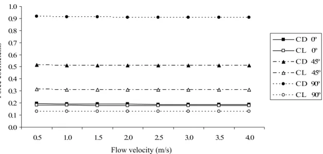
optimum mesh refinement. ...55 Figure 4: Computational fluid dynamics oil-film plot shows the direction of the water flow in the wake of the model. The flow path line at a 90º angle of attack of the hand and forearm segment is presented (sweep back angle = 0º). ...56 Figure 5: Drag and lift coefficients vs. flow velocity for each angle of attack. Sweep back angle = 0º...57 Figure 6: Drag and lift coefficients vs. flow velocity for each angle of attack. Sweep back angle = 90º...57 Figure 7: Drag and lift coefficients vs. flow velocity for each angle of attack. Sweep back angle = 180º. 58 Figure 8: Drag coefficient vs. angle of attack for each sweep back angle (SA). Flow velocity = 2.0 m/s. 59 Figure 9: Lift coefficient vs. angle of attack for each sweep back angle (SA). Flow velocity = 2.0 m/s. ..59
Study 5
Figure 1: The models of the hand with the thumb in different positions: fully abducted, partially abducted and adducted. ...68 Figure 2: The model of the hand with the thumb fully abducted inside the domain (Angle of attack = 0º,
Sweepback angle = 0º)...70 Figure 3: The angle of attack (Schleihauf, 1979). The arrow represents the direction of the flow. ...71 Figure 4: The sweep back angle (Schleihauf, 1979). The arrows represent the direction of the flow...71 Figure 5: Drag and lift coefficients vs. flow velocity for each angle of attack in the position with the
thumb fully abducted. ...72 Figure 6: Drag and lift coefficients vs. flow velocity for each angle of attack in the position with the
thumb partially abducted...73 Figure 7: Drag and lift coefficients vs. flow velocity for each angle of attack in the position with the
thumb adducted...73 Figure 8: Values of drag coefficient obtained for the different angles of attack and for the different thumb positions. Sweepback angle = 0º and flow velocity = 2.0 m/s. ...74 Figure 9: Values of lift coefficient obtained for the different angles of attack and for the different thumb
positions. Sweepback angle = 0º and flow velocity = 2.0 m/s. ...75 Figure 10: Values of the resultant force coefficient obtained for the different angles of attack and for the
different thumb positions. Sweepback angle = 0º and flow velocity = 2.0 m/s. ...75 Study 6
Figure 1: Anthropometric characteristics of the swimmer hand. Hand length (1): 20.20 cm, index breadth (2): 1.50 cm, index length (3): 8.10 cm, palm length (4): 9.50 cm, hand breadth (5): 8.90 cm. ...86 Figure 2: Computational fluid dynamics model geometry with the hand inside the domain (model with
fingers closed)...87 Figure 3: Values of CD obtained for the different attack angles and for the different finger spread.
Sweepback angle = 0º and flow velocity = 2.0 m/s. ...89 Figure 4: Values of CL obtained for the different attack angles and for the different finger spread.
Sweepback angle = 0º and flow velocity = 2.0 m/s. ...90 Review
Figure 1: Hydrodynamic drag force of the swimmer, the digital CFD model and the mannequin. Adapted from Bixler et al. (2007). ...108 Figure 2: The angle of attack (Schleihauf, 1979). The arrow represents the direction of the flow. ...111 Figure 3: The sweep back angle (Schleihauf, 1979). The arrows represent the direction of the flow...111 Figure 4: Drag coefficient vs. angle of attack for the digital model of the hand, forearm and hand/forearm (Sweep back angle = 0º). Adapted from Bixler and Riewald (2002)...111 Figure 5: Lift coefficient vs. angle of attack for the digital model of the hand, forearm and hand/forearm
Figure 6: Drag and lift coefficient of the hand/forearm model for angles of attack of 0º, 45º and 90º (SA: Sweep back angle). Flow velocity = 2.0 m/s. Adapted from Silva et al. (2008a). ...113 Figure 7: The hand and forearm model used by Silva et al. (2008a) inside the three-dimensional CFD
domain. ...113 Figure 8: Comparison between steady and accelerated drag and lift coefficients for angles of attack of 0º,
90º and 180º (Sweep back angle = 0º). Adapted from Rouboa et al. (2006)...115 Figure 9: Drag coefficient for angles of attack of 0º, 45º and 90º for the different thumb positions (Sweep
back angle = 0º, Flow velocity = 2.0 m/s). Adapted from Marinho et al. (2008d). ...118 Figure 10: Lift coefficient for angles of attack of 0º, 45º and 90º for the different thumb positions (Sweep
back angle = 0º, Flow velocity = 2.0 m/s). Adapted from Marinho et al. (2008d). ...119 Figure 11: Drag coefficient for angles of attack of 0º, 15º, 30º, 45º, 60º, 75º and 90º for the different finger
spread positions (Sweep back angle = 0º, Flow velocity = 2.0 m/s). Adapted from Marinho et al. (2008e)...120 Figure 12: Lift coefficient for angles of attack of 0º, 15º, 30º, 45º, 60º, 75º and 90º for the different finger
spread positions (Sweep back angle = 0º, Flow velocity = 2.0 m/s). Adapted from Marinho et al. (2008e)...121 Figure 13: Momentum reduction in an average second of two types of kicking movements (large/slow vs. small/fast). Adapted from Lyttle and Keys (2006). ...122 Figure 14: The model used by Marinho et al. (2008a) in a ventral position with the arms alongside the
trunk inside the CFD domain...123 Figure 15: The model used by Marinho et al. (2008a) in a ventral position with the arms extended at the
front, with the shoulders fully flexed, inside the CFD domain. ...123 Figure 16: Two-dimensional model used by Silva et al. (2008b) to determine the effect of drafting
distances on hydrodynamic drag...125 Figure 17: Relationship between total drag, skin-friction drag and pressure drag and the gliding velocity
for the positions with the arms alongside the trunk (AAT) and with the arms extended at the front with the shoulders flexed (AEF). Adapted from Marinho et al. (2008a). ...127
General introduction
Swimming is one of the major athletic sports. To swim faster, thrust should be maximized and drag should be minimized. These aims are difficult to achieve because swimmers surge, heave, roll and pitch during every stroke cycle. In addition, determining the human forces is difficult due to the restrictions of the measuring devices and the specificity of aquatic environment. Thus, human swimming evaluation is one of the most complex but outstanding and interesting topics in sport biomechanics. Over the past decades, research in swimming biomechanics has evolved from the study of swimmer’s kinematics to a flow dynamics approach, following the line of research from the experimental biology (Dickinson, 2000; Arellano et al., 2006). Significant efforts have been made to understand swimming mechanics on a deeper basis. In the past, most of the studies involved experimental data. However, nowadays the numerical solutions can give new insights about swimming science. Computational fluid dynamics (CFD) methodology is one of the different methods that have been applied in swimming research to observe and understand water movements around the human body and its application to improve swimming technique and/or swimming equipments and therefore, swimming performance. CFD methodology consists of a mathematical model that simulates the fluid flow around physical structures. Hence, the use of CFD can be considered as a new step forward to the understanding of swimming mechanisms and seems to be an interesting approach to use in swimming research. In this sense, the main purpose of the present thesis was to study the mechanism of swimming propulsion using CFD through a three-dimensional analysis of the swimmer’s hand and forearm.
After the introduction section, in which we establish the issue and the main purpose of this work, we present six studies and a review work, each of them with a particular aim. The first part of this thesis is to apply CFD in swimming using a three-dimensional model of the swimmer body (Studies 1 and 2). Although the emergence of very interesting works applying CFD in human swimming, the majority of the digital models used in the numerical simulations applied two-dimensional models of the swimmer body (Bixler and Schloder, 1996; Silva et al., 2005; Rouboa et al., 2006; Zaidi et al., 2008). Thus, in study 1, The hydrodynamic drag during the gliding in swimming, we
applied CFD in swimming using a three-dimensional model of the swimmer body. This approach allowed evaluating the drag force resisting forward motion during the swimming gliding after starts and turns. This study was our first application of a three-dimensional CFD analysis in swimming which was very important to improve our work regarding swimming propulsion. In study 2, The use of Computational Fluid Dynamics
in swimming research, it was possible to investigate the hand and forearm propulsion in
steady flow conditions applying a three-dimensional CFD analysis. Despite the contribution of this study to improve the CFD approach, the hand and forearm model used in the study was still a poor representation of the swimmer hand and forearm. The CFD analysis was performed using a three-dimensional model of the hand and forearm with the fingers slightly flexed. These differences between digital models and true human segments can lead to some misinterpretation of the biomechanical basis of human swimming propulsion. Therefore, in study 3, Design of a three-dimensional
hand/forearm model to apply Computational Fluid Dynamics, a true three-dimensional
model of the human hand and forearm was developed through the transformation of computer tomography scans into input data to apply CFD methodology. This study has shown the great potential offered by reverse engineering procedures for developing true digital models of the human body to improve the prediction of hydrodynamic forces in swimming (Studies 4, 5 and 6). The purpose of study 4, CFD analysis of the hand and
forearm propulsion in swimming, was to analyze the propulsive force produced by a
swimmer hand/forearm three-dimensional segment using a steady state CFD analysis. In this study we attempted to improve previous analysis including a more realistic model of the swimmer hand and forearm and different orientation angles of the propelling segments. In studies 5 and 6, Hydrodynamic analysis of different thumb positions in
swimming and Swimming propulsion forces are enhanced by a small finger spread, we
attempted to apply CFD to address some practical concerns of swimmers and coaches that remain controversial, such as the finger’s relative position during the underwater path of the stroke cycle. CFD was applied to study the hydrodynamic characteristics of a true model of a swimmer hand with the thumb in different abduction/adduction positions (Study 5) and with different finger spreading (Study 6). The last part (Review,
Swimming Simulation: a new tool for swimming research and practical applications) is
means emphasis on the fluid mechanics and CFD methodology applied in swimming research. In this last work, we briefly explain the CFD methodology and report the contribution of the different studies in swimming using CFD, including the studies of this thesis. This fact is the main reason why this review is the last and not the first work or even the introduction section. During this final part we discuss the main results of the CFD research in swimming and present some future directions to improve CFD in swimming investigations.
This work finishes with the main conclusions and with all the references used in this thesis. As an appendix to this thesis, the letters of acceptance of the in press papers are presented.
It seems important to underline that the studies presented in this thesis are a part of a project involving the Department of Sport Sciences, Exercise and Health and the Department of Engineering of the University of Trás-os-Montes and Alto Douro (Vila Real, Portugal). This research project entitled Computational Fluid Dynamics: an
analytical tool for the 21st century swimming research was supported by the Portuguese
Government by a grant of the Science and Technology Foundation (POCTI/DES/58872/2004). In the last four years several works have been presented in International and National Scientific Meetings and others have been published in Scientific Journals.
Study 1
Marinho, D.A., Reis, V.M., Alves, F.B., Vilas-Boas, J.P., Machado, L., Silva, A.J., Rouboa, A.I. (2008). The hydrodynamic drag during the gliding in swimming.
Journal of Applied Biomechanics (in press).
Study 2
Marinho, D.A., Reis, V.M., Alves, F.B., Vilas-Boas, J.P., Machado, L., Rouboa, A.I., Silva, A.J. (2008). The use of Computational Fluid Dynamics in swimming research. International Journal for Computational Vision and Biomechanics (in press).
Study 3
Marinho, D.A., Reis, V.M., Vilas-Boas, J.P., Alves, F.B., Machado, L., Rouboa, A.I., Silva, A.J. (2008). Design of a three-dimensional hand/forearm model to apply Computational Fluid Dynamics. Brazilian Archives of Biology and Technology (in press).
Study 4
Marinho, D.A., Vilas-Boas, J.P., Alves, F.B., Machado, L., Barbosa, T.M., Reis, V.M., Rouboa, A.I., Silva, A.J. (2008). Computational analysis of the hand and forearm propulsion in swimming. International Journal of Sports Medicine (under revision).
Study 5
Marinho, D.A., Rouboa, A.I., Alves, F.B., Vilas-Boas, J.P., Machado, L., Reis, V.M., Silva, A.J. (2008). Hydrodynamic analysis of different thumb positions in swimming. Journal of Sports Science and Medicine (in press).
Study 6
Marinho, D.A., Barbosa, T.M., Reis, V.M., Kjendlie, P.L., Alves, F.B., Vilas-Boas, J.P., Machado, L., Silva, A.J., Rouboa, A.I. (2008). Swimming propulsion forces are enhanced by a small finger spread. Journal of Applied Biomechanics (under revision).
Review
Marinho, D.A., Barbosa, T.M., Kjendlie, P.L., Vilas-Boas, J.P., Alves, F.B., Rouboa, A.I., Silva, A.J. (2009). Swimming simulation: a new tool for swimming research and practical applications. In: M. Peters (Ed.), Lecture Notes in Computational
Study 1
The hydrodynamic drag during the gliding in swimming
Marinho, D.A., Reis, V.M., Alves, F.B., Vilas-Boas, J.P., Machado, L., Silva, A.J., Rouboa, A.I. (2008). The hydrodynamic drag during the gliding in swimming. Journal of Applied Biomechanics (in press).
The hydrodynamic drag during the gliding in swimming
Abstract
This study used computational fluid dynamics methodology to analyse the effect of body position on the drag coefficient during submerged gliding in swimming. The k-epsilon turbulent model implemented in the commercial code Fluent® and applied to the flow around a three-dimensional model of a male adult
swimmer was used. Two common gliding positions were investigated: a ventral position with the arms extended at the front, and a ventral position with the arms placed along side the trunk. The simulations were applied to flow velocities between 1.6 and 2.0 m/s, which are typical of elite swimmers when gliding underwater at the start and in the turns. The gliding position with the arms extended at the front produced lower drag coefficients than with the arms placed along the trunk. We therefore recommend that swimmers adopt the arms in front position rather than the arms beside the trunk position during the underwater gliding.
Introduction
The underwater phases of swimming after starts and turns are a large and important component of the total event time in modern swimming. Accordingly, Guimarães and Hay (1985) refer, for instance, that it is essential to minimize the hydrodynamic drag during the gliding. Thus, the swimmer must adopt the most hydrodynamic position possible. Race analysis has suggested that rather than the start position used by the swimmer it is his body alignment under the water that mostly determines the success of the start (Vilas-Boas et al., 2000; Cossor and Mason, 2001).
The passive drag of swimmers moving underwater in a streamlined position has been measured experimentally (for example, Jiskoot and Clarys, 1975; Lyttle et al., 2000). These studies revealed the difficulties involved in conducting such experimental research. An alternative approach is to apply the numerical technique of computational fluid dynamics to determine a swimmer’s passive drag.
The first application of computational fluid dynamics to swimming was conducted by Bixler and Schloder (1996). They used a two-dimensional numerical analysis to evaluate the effects of accelerating a hand-sized disc through the water. Additional research using computational fluid dynamics techniques was performed by Rouboa et
al. (2006) to evaluate the steady and unsteady propulsive force of a swimmer’s hand and arm. Their results suggested that a three-dimensional computational fluid dynamics analysis of a human form could provide useful information about swimming. This was already confirmed by Alves et al. (2007), in the upper arm propulsion, and by Bixler et al. (2007), in the analysis of an entire swimmer’s body drag. Hence, the main aim of this study was to analyse the effect in the drag coefficient of the use of two distinct ventral positions during the underwater gliding in swimming, applying computational fluid dynamics. A second aim was to study the relative contributions of the skin friction drag and the pressure drag for the total drag during the gliding.
Methods
Three-dimensional model
To obtain the geometry of a human body, a model was created in CAD (Computer-Aided Design), based on the anthropometrical characteristics of a group of elite national level male swimmers. The surfaces of the swimmer were then developed using Gambit, a geometry modelling program of Fluent (Fluent®, Inc. Hannover, USA), which provides sophisticated computational fluid dynamics software. These surfaces were then meshed, creating the volume mesh which has been imported into Fluent® computational fluid dynamics program for analysis (Figure 1).
Figure 1: Swimmer’s model geometry with the surfaces meshed using Gambit. An example for the position with the arms along the trunk is presented.
Computational fluid dynamics model
The swimmer was modelled as if he were gliding underwater in one of two distinct ventral positions. The first position was a streamlined position, with the arms extended at the front. This is the shape usually adopted after the start and after pushing off from the wall after a turn. The second position was with the arms along the trunk. This is the shape adopted by the swimmers during the second gliding phase after a turn in breaststroke.
The computational fluid dynamics analyses were performed with the body in a horizontal position with an attack angle of 0º. The attack angle was defined as the angle between a horizontal line and a line drawn from the vertex to the ankle bone.
The swimmer’s model used for the analysis was 1.87 m tall with head, chest, waist and hip circumferences of 0.57 m, 1.04 m, 0.85 m and 0.95 m, respectively. In the streamlined position, the model had a finger to toe length of 2.37 m and in the position with the arms along the trunk the distance from vertex to toe was 1.92 m.
The boundary conditions of the computational fluid dynamics model were designed to represent the geometry and flow conditions of a part of a lane in a swimming pool. The water depth of the model was 1.80 m with a 2.50 m width. The length was 8.0 m in the streamlined position and 7.55 m in the position with the arms along the trunk, allowing in both situations the same flow conditions behind and in front of the swimmer. In both positions, the distance to the front surface was 2.0 m and to the back surface was 3.63 m. The swimmer model middle line was placed at a water depth of 0.90 m, equidistant from the top and bottom surfaces (Figure 2).
The model’s body surface had roughness parameters of zero. The whole domain was meshed with 900 million cells. The grid was a hybrid mesh composed of prisms and pyramids. Significant efforts were conducted to ensure that the model would provide accurate results, namely by decreasing the grid node separation in areas of high velocity and pressure gradients.
Figure 2: Computational fluid dynamics model geometry with the swimmer with the arms extended at the front. The water depth is 1.80 m, the width is 2.50 m and the length is 8.0 m.
Steady-state computational fluid dynamics analyses were performed using the Fluent® code and the drag coefficient was calculated for velocities ranging from 1.60 to 2.0 m/s in increments of 0.10 m/s. Flow velocities were chosen to be within the range of typical underwater gliding velocities at the start and in the turns. The Fluent® code solves flow problems by replacing the Navier-Stokes equations with discretized algebraic expressions that can be solved by iterative computerized calculations. Fluent® uses the finite volume approach, where the equations are integrated over each control volume. We used the segregated solver with the standard k-epsilon turbulence model because this turbulence model was shown to be accurate with measured values in a previous research (Moreira et al., 2006).
All numerical computational schemes were second-order, which provides a more accurate solution than first-order schemes. We used a turbulence intensity of 1.0% and a turbulence scale of 0.10 m. The water temperature was 28º C with a density of 998.2 kg/m3 and a viscosity of 0.001 kg/mm/s. Incompressible flow was assumed.
In human swimming, the total drag is composed of the skin friction drag, pressure drag and wave drag. Skin friction drag is attributed to the forces tending to slow the water flowing along the surface of a swimmer's body. It depends on the velocity of the flow, the surface area of the body and the characteristics of the surface. Pressure drag is caused by the pressure differential between the front and the rear of the swimmer and it is proportional to the square of swimming velocity, the density of water and the cross sectional area of the swimmer. Finally, swimming at the water surface is constrained by the formation of surface waves leading to wave drag. In this study we considered
hydrodynamic drag depending only on the skin friction and pressure drag since the model was placed 0.90 m underwater. These two drag components were computed by Fluent® software.
Statistical analyses
To analyse the relationship between the velocity and the drag coefficient, regression lines between these parameters were computed. The regression equations were calculated and the R2 value was used as a measure of the robustness of the model.
Results
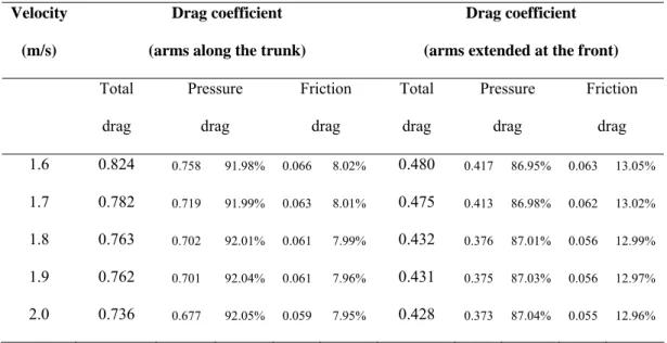
Table 1 shows the drag coefficient values produced by both models: with the arms along the trunk and with the arms extended at the front. The percentage and the absolute values of total drag due to skin friction and pressure drag are also presented.
Table 1: Drag coefficient values and contribution of pressure and skin friction drag for the total drag to each velocity and for the two different gliding positions.
Velocity Drag coefficient Drag coefficient
(m/s) (arms along the trunk) (arms extended at the front)
Total drag Pressure drag Friction drag Total drag Pressure drag Friction drag 1.6 0.824 0.758 91.98% 0.066 8.02% 0.480 0.417 86.95% 0.063 13.05% 1.7 0.782 0.719 91.99% 0.063 8.01% 0.475 0.413 86.98% 0.062 13.02% 1.8 0.763 0.702 92.01% 0.061 7.99% 0.432 0.376 87.01% 0.056 12.99% 1.9 0.762 0.701 92.04% 0.061 7.96% 0.431 0.375 87.03% 0.056 12.97% 2.0 0.736 0.677 92.05% 0.059 7.95% 0.428 0.373 87.04% 0.055 12.96%
For all the velocities, the drag coefficient of the position with the arms extended at the front was lower than the drag coefficient of the position with the arms along the trunk. Moreover, the pressure drag was dominant, with a percentage of about 92% and 87% of
the total drag, in the position with the arms along the trunk and with the arms extended at the front, respectively. The absolute values of skin friction drag were quite similar in both positions.
On the other hand, in both positions, the drag coefficient of the model decreased with the velocity (Table 1 and Figure 3).
Arms along the trunk 0,90 y = -0,1975x + 1,1287 R2 = 0,90 y = -0,148x + 0,7156 R2 = 0,81 Veloci .s-1) 0,20 0,30 0,40 0,50 0,60 0,70 0,80 0.90
Arms extended at the front 0.80 y = -0.1975x + 1.1287 0.70 Dra g c oefficient R2 = 0.90 0.60 0.50 0.40 y = -0.1480x + 0.7156 R2 = 0.81 0.30 0.20 1,50 1,60 1,70 1,80 1,90 2,00 1.5 1.6 1.7 1.8 1.9 2.0 ty (m Velocity (m/s)
Figure 3: Relationship between the drag coefficient and the velocity for the two different gliding positions. The regression equations and the R2 values are also presented.
Discussion
The main aim of this study was to analyse the drag coefficient arising from the use of two different gliding positions in swimming, through computational fluid dynamics. The drag coefficient changed slightly from 0.824 at 1.60 m/s to 0.736 at 2.00 m/s, in the position with the arms along the trunk, and from 0.480 at 1.60 m/s to 0.428 at 2.00 m/s, in the position with the arms extended at the front. The inverse relationship between the drag coefficient and the velocity found in the present study seems to correspond to what happens in experimental situations with the human body totally submersed (Jiskoot and Clarys, 1975; Lyttle et al., 2000).
Moreover, the gliding position with the arms extended at the front presented lower drag coefficient values than the position with the arms placed along the trunk. This body position, with the arms at the front, is mostly accepted by the swimming technical and scientific communities as the most hydrodynamic one, being called the streamlined position (Guimarães and Hay, 1985). The position with the arms extended at the front seems to be the one that allows a higher reduction of the negative hydrodynamic effects of the human body morphology: a body with various pressure points due to the large changes in its shape. This position seems to smooth the anatomical shape especially at the head and shoulders. Considering the breaststroke turn, the first gliding, performed with the arms at the front, must be emphasized in relation to the second gliding, performed with the arms along the trunk.
Bixler et al. (2007) demonstrated the validity of computational fluid dynamics analysis as a tool to examine the water flow around a submerged swimmer’s body. This form of research has opened a new gate of analysis into the swimming hydrodynamics and has been shown to hold promise as a way to assess the flow characteristics and associated drag forces experienced by swimmers, for instance, in different gliding positions after starts and turns.
Another aim of the present study was to analyze the influence of the skin friction drag and the pressure drag in the total drag during the gliding. We choose a pool depth of 1.80 m, with the swimmer model placed at the midpoint between top and bottom, to avoid significant wave drag, limiting our research to the influence of the pressure drag and the skin friction drag in the total drag coefficient. Lyttle et al. (1999) concluded that there is no significant wave drag when a typical adult swimmer is at least 0.6 m under the water’s surface.
The computed drag forces components showed that for both gliding positions the pressure drag was dominant. Nevertheless, skin friction drag was by no means negligible, presenting an absolute value of about 0.06. This drag component represented ≈13% and ≈8% of total drag in the position with the arms extended at the front and with the arms along the trunk, respectively. However, these values are based on the swimmer model’s surface having a zero roughness. Therefore, the development of roughness parameters for human skin would allow a more accurate computational fluid dynamics
model to be built in further studies. Since this task is still in development, we assumed to conduct our simulations based upon the swimmer’s surface having a zero roughness. We chose this value as a first step in the application of numerical simulation techniques in swimming research, using a three-dimensional model of a whole human body. We had to opt between a certain value and a zero value. Indeed, we simulated a situation as the swimmer was shaved (smoothed), with roughness zero. In our opinion, the change in the roughness parameter would affect each body position in approximately the same way and our main finding would be the same. However, the contribution of each drag component would possibly be a little different with the use of a roughness skin value. Nevertheless, we are convinced that the pressure drag would be dominant and the skin friction drag would be important as well. How this relative contribution would be changed is a very interesting question, which could lead to further research. But one can speculate about this. On one hand, if the surface roughness were increased in the model, the skin friction drag would probably be higher. It is expected that the surface roughness increase could lead to increase the turbulence around the surface, thus increasing skin friction drag. On the other hand, if the surface roughness were increased the pressure drag could be reduced. The boundary layer, which would be mainly laminar, would change into a turbulent one (Massey, 1989). When the flow regime is laminar, separation at the body surface starts almost as soon as the pressure gradient becomes adverse and a larger wake forms while when the flow regime is turbulent, separation is delayed and the corresponding wake is smaller, thus decreasing pressure drag. The importance of keeping the boundary layer attached to the swimmer body surface is so important that swimwear manufacturers sometimes purposely cause the boundary layer to become turbulent (Polidori et al., 2006).
Moreover, since the absolute values of skin friction drag are about the same in the two gliding positions, it is possible that the increase in this component would be approximately the same. The main difference could occur at the pressure drag since the position with the arms along the trunk presented higher absolute values. It is expected that the drag force decrease in this body position would be more accentuated, thus decreasing the differences between the two models. However, we think these changes would not be sufficient to have an effect on our primary finding: the gliding position
with the arms extended at the front produced lower drag coefficients than with the arms placed along the trunk.
Another different situation could happen if the swimmer were at the water’s surface. The contribution of the skin friction drag would be reduced due to the reduction in the wetted area and the generation of wave drag (Bixler et al., 2007).
Although limited to passive drag, this study allowed the evaluation of the effects of different body positions on performance, being a first step towards the analysis of active drag. On the other hand, computational fluid dynamics methods have provided a way to estimate the relative contribution of each drag component to the total drag. Future studies could improve this computational fluid dynamics results by analysing the passive drag of a swimmer at the water’s surface and including wave drag in the measurements. Moreover, the evaluation of the active drag while the swimmer is kicking must also be attempted in the future.
References
Alves, F., Marinho, D., Leal, L., Rouboa, A., Silva, A. (2007). 3-D computational fluid dynamics of the hand and forearm in swimming. Medicine and Science in Sports and Exercise, 39(Suppl. 1), S9. Bixler, B.S., Schloder, M. (1996). Computational fluid dynamics: an analytical tool for the 21st century
swimming scientist. Journal of Swimming Research, 11, 4-22.
Bixler, B., Pease, D., Fairhurst, F. (2007). The accuracy of computational fluid dynamics analysis of the passive drag of a male swimmer. Sports Biomechanics, 6, 81-98.
Cossor, J., Mason, B. (2001). Swim start performances at the Sydney 2000 Olympic Games. In: J. Blackwell, R. Sanders (Eds.), Proceedings of Swim Sessions of the XIX Symposium on Biomechanics in Sports, pp. 70-74. San Francisco: University of San Francisco.
Guimarães, A., Hay, J. (1985). A mechanical analysis of the grab starting technique in swimming. International Journal of Sports Biomechanics, 1, 25-35.
Jiskoot, J., Clarys, J.P. (1975). Body resistance on and under the water surface. In: L. Lewillie, J.P. Clarys (Eds.), Swimming II, pp. 105-109. Baltimore: University Park Press.
Lyttle, A.D., Blanksby, B.A., Elliott, B.C., Lloyd, D.G. (1999). Optimal depth for streamlined gliding. In: K.L. Keskinen, P.V. Komi, A.P. Hollander (Eds.), Biomechanics and Medicine in Swimming VIII, pp. 165-170. Jyvaskyla: Gummerus Printing.
Lyttle, A., Blanksby, B., Elliot, B., Lloyd, D. (2000). Net forces during tethered simulation of underwater streamlined gliding and kicking technique of the freestyle turn. Journal of Sports Sciences, 18, 801-807.
Massey, B.S. (1989). Mechanics of Fluids. London: Chapman & Hall.
Moreira, A., Rouboa, A., Silva, A., Sousa, L., Marinho, D., Alves, F., Reis, V., Vilas-Boas, J.P., Carneiro, A., Machado, L. (2006). Computational analysis of the turbulent flow around a cylinder. Portuguese Journal of Sport Sciences, 6(Suppl. 1), 105.
Polidori, G., Taiar, R., Fohanno, S., Mai, T.H., Lodini, A. (2006). Skin-friction drag analysis from the forced convection modeling in simplified underwater swimming. Journal of Biomechanics, 39, 2535-2541.
Rouboa, A., Silva, A., Leal, L., Rocha, J., Alves, F. (2006). The effect of swimmer’s hand/forearm acceleration on propulsive forces generation using computational fluid dynamics. Journal of Biomechanics, 39, 1239-1248.
Vilas-Boas, J.P., Cruz, M.J., Sousa, F., Conceição, F., Carvalho, J.M. (2000). Integrated kinematic and dynamic analysis of two track-start techniques. In: R. Sanders, Y. Hong (Eds.), Proceedings of the XVIII International Symposium on Biomechanics in Sports, Applied Program – Application of Biomechanical Study in Swimming, pp. 113-117. Hong Kong: The Chinese University Press.
Study 2
The use of Computational Fluid Dynamics in swimming research
Marinho, D.A., Reis, V.M., Alves, F.B., Vilas-Boas, J.P., Machado, L., Rouboa, A.I., Silva, A.J. (2008). The use of Computational Fluid Dynamics in swimming research. International Journal for Computational Vision and Biomechanics (in press).
The use of Computational Fluid Dynamics in swimming research
Abstract
The aim of the present study was to apply Computational Fluid Dynamics to the study of the hand/forearm forces in swimming using a three-dimensional model. Models used in the simulations were created in CAD, based on real dimensions of a right adult human hand/forearm. The governing system of equations considered was the incompressible Reynolds averaged Navier-Stokes equations implemented in the Fluent® commercial code. The drag coefficient was the main responsible for propulsion, with a
maximum value of force propulsion corresponding to a pitch angle of 90º. The lift coefficient seemed to play a less important role in the generation of propulsive force with pitch angles of 0º and 90º but it is important with pitch angles of 30º, 45º and 60º.
Introduction
The creation of propulsive force in human swimming has been recently studied using numerical simulation techniques with computational fluid dynamics (CFD) models (Bixler and Schloder, 1996; Bixler and Riewald, 2002; Silva et al., 2005; Rouboa et al., 2006; Gardano and Dabnichki, 2006).
Nevertheless, some limitations still persist, regarding the geometrical representation of the human limbs. In the pioneer study of Bixler and Schloder (1996), these authors used a disc with a similar area of a swimmer hand, while Gardano and Dabnichki (2006) used standard geometric solids to represent the superior limb. Rouboa et al. (2006) tried to correct and to complement the backward works using a two-dimensional (2-D) model of a hand and a forearm of a swimmer, situation that seems to be an important step forward in the application of CFD to the human propulsion. However, it seems it is possible to go forward, reason why we propose to apply CFD to the studied of the hand and forearm propulsion with three-dimensional (3-D) models, as it was already experimented by Lyttle and Keys (2006) to analyse the dolphin kicking propulsion. In this sense, with this work we want to continue using CFD as a new technology in the swimming research, applying CFD to the 3-D study of the propulsion produced by the swimmer hand and forearm. Therefore, the aim of the present study is twofold. First, continuing to disseminate the use of CFD as a new tool in swimming research. Second,
to apply the method in the determination of the relative contribution of drag and lift coefficients resulting from the numerical resolution equations of the flow around the swimmers hand and forearm using 3-D models under the steady flow conditions.
Methods
Mathematical model
The dynamic fluid forces produced by the hand/forearm, drag (D) and lift (L), were measured in this study. These forces are function of the fluid velocity and they were measured by the application of the equations 1 and 2.
D = CD ½ ρ A V2 (1)
L = CL ½ ρ A V2 (2)
In equations 1 and 2, V is the fluid velocity, CD and CL are the drag and lift coefficients,
respectively, ρ is the fluid density and A is the projection area of the model for different angles of pitch used in this study (0º, 30º, 45º, 60º, 90º).
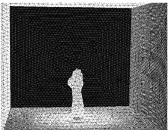
CFD methodology consists of a mathematical model applied to the fluid flow in a given domain that replaces the Navier-Stokes equations with discretized algebraic expressions that can be solved by iterative computerized calculations. This domain consists of a three-dimensional grid or mesh of cells that simulate the fluid flow (Figure 1). The fluid mechanical properties, the flow characteristics along the outside grid boundaries and the mathematical relationship to account the turbulence were considered.
We used the segregated solver with the standard k-epsilon turbulence model because this turbulence model was shown to be accurate with measured values in a previous research (Moreira et al., 2006).
Figure 1: Hand and forearm model inside the domain with 3-D mesh of cells.
Resolution method
The whole domain was meshed with 400000 elements. The grid was a hybrid mesh composed of prisms and pyramids. The numerical method used by Fluent® is based on the finite volume approach. The steady solutions of the governing system equations are given in each square element of the discretized whole domain. In order to solve the linear system, Fluent® code adopts an AMG (Algebraic Multi-Grid) solver. Velocity components, pressure, turbulence kinetic energy and turbulence kinetic energy dissipation rate are a degree of freedom for each element.
The convergence criteria of AMG are 10-3 for the velocity components, the pressure, the turbulence kinetic energy and the turbulence kinetic energy dissipation ratio.
The numerical simulation was carried out in three-dimensions (3-D) for the computational whole domain in steady regime.
Application
In order to make possible this study we analysed the numerical simulations of a 3-D model of a swimmer hand and forearm. Models used in the simulations were created in CAD, based on real dimensions of a right adult human hand/forearm.
Angles of pitch of hand/forearm model of 0º, 30º, 45º, 60º and 90º, with a sweep back angle of 0º (thumb as the leading edge) were used for the calculations (Schleihauf, 1979).
On the left side of the domain access (figure 1), the x component of the velocity was chosen to be within or near the range of typical hand velocities during freestyle swimming underwater path: from 0.5 m/s to 4 m/s, with 0.5 m/s increments. The y and z components of the velocity were assumed to be equal to zero. On the right side, the pressure was equal to 1 atm, fundamental pre requisite for not allowing the reflection of the flow.
Around the model, the three components of the velocity were considered as equal to zero. This allows the adhesion of the fluid to the model.
It was also considered the action of the gravity force (g = 9.81 m/s2), as well as the
turbulence percentage of 1% with 0.1 m of length.
The considered fluid was water, incompressible with density (ρ = 996.6 x 10⁻⁹ kg/mm3) and viscosity (μ = 8.571 x 10⁻⁷ kg/mm/s).
The measured forces on the hand/forearm model were decomposed into drag and lift components. The combined hand and forearm drag (CD) and lift (CL) coefficients were
calculated, using equations 1 and 2. The independent variables were the angle of pitch and fluid boundary velocity. The dependent variables were pressure and velocity of the fluid within the dome. Post-processing of the results with Fluent® allowed the calculation of component forces through integration of pressures on the hand/forearm surfaces (Figure 2).
Results
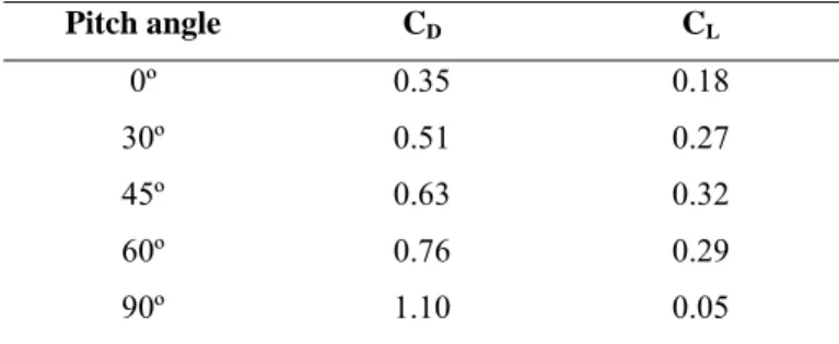
In table 1 it is possible to observe the CD and CL values produced by the hand/forearm
segment as a function of pitch angle. It is presented the values found for a flow velocity of 2.00 m/s with a sweep back angle of 0º.
Table 1: Values of CD and CL of the hand/forearm segment as a function of pitch angle. Sweep back angle
= 0º and flow velocity = 2.00 m/s.
Pitch angle CD CL 0º 0.35 0.18 30º 0.51 0.27 45º 0.63 0.32 60º 0.76 0.29 90º 1.10 0.05
The CD and CL values were almost constant for the whole range of velocities (for a
given pitch angle).
According to the obtained results, hand/forearm drag was the coefficient that accounts more for propulsion, with a maximum value of 1.10 for the model with an angle of pitch of 90º. The CD values increased with the angle of pitch. Moreover, CL seems to play a
residual influence in the generation of propulsive force by the hand/forearm segment at angles of pitch of 0º and 90º, but it is important with angles of pitch of 30º, 45º and 60º.
Discussion
The aim of the present study was to apply Computational Fluid Dynamics to the study of the hand/forearm forces in swimming using a 3-D model and to determine the relative contribution of drag and lift coefficients to the overall propulsive force production.
Computational Fluid Dynamics methodology was developed by engineers to solve numerically complex problems of fluid flow using an iterative optimization approach. The net effect is to allow the user to model computationally any flow field provided the geometry of the object and some initial flow conditions are prescribed. This can provide
answers to problems which have been unobtainable using physical testing methods, thereby bridging the gap between theoretical and experimental fluid dynamics. In this research we tried to improve the previous studies that applied CFD to the analysis of swimming propulsion, using a more realistic model of the swimmer hand and forearm (3-D model). Thought, this model still needs to be improved, namely using a model in which the fingers would be extended. This is an issue that should be addressed in future studies.
We are very pleased with the results pointed out in the simulations of our study. CD was
the main responsible for propulsion, with the maximum value of force production corresponding to an angle of pitch of 90º, as expected. The CD obtained the highest
value at an orientation of the hand/forearm plane where the model was directly perpendicular to the direction of the flow. The same result was reported by Berger et al. (1995), in which the drag force increases to a maximum where the plane was the same as the presented in this work (angle of pitch = 90º).
CL has a residual influence in the generation of propulsive force by the hand/forearm
segment for angles of pitch of 0º and 90º, but it is important with angles of pitch of 30º, 45º and 60º. These data confirm recent studies reporting reduced contribution of lift component to the overall propulsive force generation by the hand/forearm segment in front crawl swimming, except for the insweep phase, when the angle of attack is within 30º-60º (Berger et al., 1995; Sanders, 1999; Bixler and Riewald, 2002; Rouboa et al., 2006).
Although in this study we had only tested flow in steady regime and this situation does not truly represent what happens during swimming, the present study allowed us to apply CFD in the study of propulsive forces in swimming, using a three-dimensional model of a human hand/forearm. By itself, this situation seems to be an important step to the advancement of this technology in sports scope.
The results of the values of CD and CL are similar to the ones found in experimental
studies (Wood, 1977; Schleihauf, 1979; Berger et al., 1995; Sanders, 1999), important fact to the methodological validation of CFD, giving as well conditions to the primary acceptation to the analysis of hydrodynamic forces produced through unsteady flow conditions and through different orientations of the propelling segments.
For the three different orientation models and for the whole studied velocity range, the CD and CL remain constant. Similar results were observed as well in other studies using
CFD (Bixler and Riewald, 2002; Silva et al., 2005; Rouboa et al., 2006).
Conclusion
This study tried to apply CFD to the analysis of swimming propulsion. As conclusions we can state that the computational data found seem to demonstrate an important role of the drag force and a minor contribution of the lift force to the propulsive force production by the swimmer hand/forearm segment.
On the other hand, it was demonstrated the utility of using CFD in the propulsive force measurements, using a more realistic model (3-D) of a human segment. This situation is an additional step forward to the necessary continuation to keep developing this technology in sport studies, in general, and in swimming, as a particular case.
References
Berger, M.A., de Groot, G., Hollander, AP. (1995). Hydrodynamic drag and lift forces on human hand arm models. Journal of Biomechanics, 28, 125-133.
Bixler, B.S., Schloder, M. (1996). Computational fluid dynamics: an analytical tool for the 21st century swimming scientist. Journal of Swimming Research, 11, 4-22.
Bixler, B.S., Riewald, S. (2002). Analysis of swimmer’s hand and arm in steady flow conditions using computational fluid dynamics. Journal of Biomechanics, 35, 713-717.
Gardano, P., Dabnichki, P. (2006). On hydrodynamics of drag and lift of the human arm. Journal of Biomechanics, 39, 2767-2773.
Lyttle, A., Keys, M. (2006). The application of computational fluid dynamics for technique prescription in underwater kicking. Portuguese Journal of Sport Sciences, 6(Suppl. 2), 233-235.
Moreira, A., Rouboa, A., Silva, A.J., Sousa, L., Marinho, D., Alves, F., Reis, V., Vilas-Boas, J.P., Carneiro, A., Machado, L. (2006). Computational analysis of the turbulent flow around a cylinder. Portuguese Journal of Sport Sciences, 6(Suppl. 1), 105.
Rouboa, A, Silva, A., Leal, L., Rocha, J., Alves, F. (2006). The effect of swimmer’s hand/forearm acceleration on propulsive forces generation using computational fluid dynamics. Journal of Biomechanics, 39, 1239-1248.
Sanders, R.H. (1999). Hydrodynamic characteristics of a swimmer’s hand. Journal of Applied Biomechanics, 15, 3-26.
Schleihauf, R.E. (1979). A hydrodynamic analysis of swimming propulsion. In: J. Terauds, E.W. Bedingfield (Eds), Swimming III, pp. 70-109. Baltimore: University Park Press.
Silva, A., Rouboa, A., Leal, L., Rocha, J., Alves, F., Moreira, A., Reis, V., Vilas-Boas, J.P. (2005). Measurement of swimmer's hand/forearm propulsive forces generation using computational fluid dynamics. Portuguese Journal of Sport Sciences, 5, 288-297.
Wood, T.C. (1977). A fluid dynamic analysis of the propulsive potential of the hand and forearm in swimming. Master of Science Thesis. Halifax, NS: Dalhouise University Press.
Study 3
Design of a three-dimensional hand/forearm model to apply
Computational Fluid Dynamics
Marinho, D.A., Reis, V.M., Vilas-Boas, J.P., Alves, F.B., Machado, L., Rouboa, A.I. and Silva, A.J. (2008). Design of a three-dimensional hand/forearm model to apply Computational Fluid Dynamics. Brazilian Archives of Biology and Technology (in press).
Design of a three-dimensional hand/forearm model to apply
Computational Fluid Dynamics
Abstract
The purpose of this study was to develop a three-dimensional digital model of a human hand and forearm to apply Computational Fluid Dynamics to propulsion analysis in swimming. Computer tomography scans of the hand and forearm of an Olympic swimmer were applied. The data were converted, using image processing techniques, into relevant coordinate input, which can be used in Computational Fluid Dynamics software. From that analysis it was possible to verify an almost perfect agreement between the true human segment and the digital model. This technique can be used as a means to overcome the difficulties in developing a true three-dimensional model of a specific segment of the human body. Additionally, it may be used to improve the use of Computational Fluid Dynamics generally in sports and specifically in swimming studies, decreasing the gap between the experimental and the computational data.
Introduction
The finite element method is currently one of the best established numerical tools in the field of biomechanical engineering and has been used in the computational analysis of the fluid flow around human structures. In the sports scope, it has been used in the study of the propulsive forces produced by the hand and forearm in human swimming. Despite the increasing amount of high quality research, a common weakness still remains. Practically all the models have been developed based on approximate analytical representations of the human structures and their geometrical accuracy has never been discussed. This approach has been commonly adopted, for example, to reduce the computational cost of memory requirements (Aritan et al., 1997). However, one of the main reasons for such limitations is the difficulty to design a true digital model of the human limbs.
In most cases, the authors used two-dimensional models (Bixler and Schloder, 1996; Silva et al., 2005; Rouboa et al., 2006) and when three-dimensional models were used, these were very simple and reductive representations of the human limbs (Gardano and Dabnichki, 2006). These differences between true and computed models could lead to less accurate numerical results (Candalai and Reddy, 1992). In an experimental
simulation of the effect of the ischial tuberosity’s geometry on the shear and compressive stress in buttock tissue, Candalai and Reddy (1992) showed that the influence of the geometry on the stress magnitude could be significant. In a numerical simulation of this experimental work, a possible variation of more than 60% was found in the shear stress.
Magnetic resonance imaging and computer tomography scans seem to be a good approach for designing true human models. However, the use of these kinds of scans is not a straightforward task and requires the implementation of image processing and other numerical techniques, such as the conversion into relevant coordinate input. It should be noted that mesh generation, the first step in finite element modeling, is a tough procedure, especially when solving three-dimensional problems (Aritan et al., 1997). Ideally, a mesh should allow modifications, usually by changing some predefined parameters and it should be based on directly obtained anatomical data. Thus, it is important to use the magnetic resonance imaging or the computer tomography data to provide geometrical input for generation or modification of finite element models. Most of the well established finite element software packages provide special tools for parametric modification of an existing mesh. These tools help the user to reduce the time and to increase the accuracy and reliability of model modifications. Therefore, the aim of the present study was to develop a true three-dimensional model of the human hand and forearm, through the transformation of computer tomography scans into input data to apply Computational Fluid Dynamics to the propulsion analysis in swimming.
Materials and Methods
Computational Fluid Dynamics
Computational Fluid Dynamics methodology consists of a mathematical model applied to the fluid flow in a given domain. This domain replaces the Navier-Stokes equations with discretized algebraic expressions that can be solved by iterative calculations. This domain consists of a three-dimensional grid or mesh of cells that simulates the fluid flow around structures. The fluid mechanical properties, the flow characteristics along
the outside grid boundaries and the mathematical relationship to account the turbulence were also considered:
0 divV= (1)
(
V V)
0 k c v p V . V t V 2 ∇ +∇ t = ⎟⎟ ⎠ ⎞ ⎜⎜ ⎝ ⎛ ε + ∇ ± ∇ + ∇ ± ∂ ∂ μ (2) ρε k k k k k k k k k k + − ∂ ⎟⎟ ⎠ ⎞ ⎜⎜ ⎝ ⎛ ∂ ∂ ∂ + ∂ ⎟⎟ ⎠ ⎞ ⎜⎜ ⎝ ⎛ ∂ ∂ ∂ + ∂ ⎟⎟ ⎠ ⎞ ⎜⎜ ⎝ ⎛ ∂ ∂ ∂ = ∂ ∂ + ∂ ∂ + ∂ ∂ + ∂ ∂ μ Φ z z σ μ y y σ μ x x σ μ z ) V ( y ) V ( x ) V ( t ) ( t t t t z y x ρ ρ ρ ρ (3) k ρ ε k ε ε ε ε ε ρ V ε ρ V ε ρ V ρ k ε ε ε 2 t t t t z y x z z y y x x z ) ( y ) ( x ) ( t ) ( Φ C 2 − μ + ∂ ⎟⎟ ⎠ ⎞ ⎜⎜ ⎝ ⎛ ∂ ∂ σ μ ∂ + ∂ ⎟⎟ ⎠ ⎞ ⎜⎜ ⎝ ⎛ ∂ ∂ σ μ ∂ + ∂ ⎟⎟ ⎠ ⎞ ⎜⎜ ⎝ ⎛ ∂ ∂ σ μ ∂ = ∂ ∂ + ∂ ∂ + ∂ ∂ + ∂ ∂ (4)Where k is the turbulent kinetic energy and ε is the turbulent kinetic energy dissipation ratio. Vx, Vy and Vz represent the x, y and z components of the velocity V. μt is the
turbulent viscosity and ρ represents the fluid density. υ is the kinematic viscosity, Ф is the pressure strain, C2, Cμ, σε and σk are model constants, 1.92, 0.09, 1.30 and 1.00,
respectively.
In order to create the three-dimensional digital model we applied computer tomography scans of a hand and forearm segments of an Olympic swimmer. With these data we converted the values into a format that can be read in Gambit, Fluent® pre-processor. Fluent® software is used to simulate the fluid flow around structures, allowing the analysis of values of pressure and speed around (i.e. the hand and forearm of a swimmer). With these values we can calculate force components through integration of pressures on the hand/forearm surfaces, using a realistic model of these human segments, thus decreasing the gap between the experimental and the computational data. The numerical method used by Fluent® is based on the finite volume approach. The solutions of the governing system equations are given in each square element of the discretized whole domain. In order to solve the linear system, Fluent® code adopts an
energy and turbulent kinetic energy dissipation ratio are degrees of freedom (DOF) for each element.
Computer tomography scans
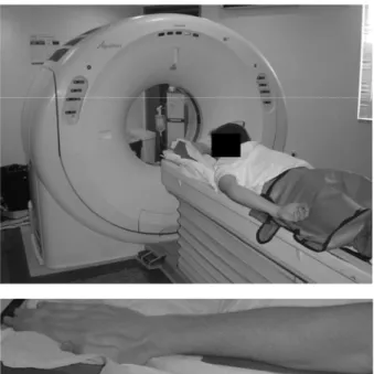
Eighteen cross-sectional scans of the right arm (hand and forearm) were obtained using a Toshiba® Aquilion 4 computer tomography scanner. Computer tomography scans were obtained with configuration of V2.04 ER001. A 2 mm slice thickness with a space of 1 mm was used. The subject was an Olympic level swimmer, who participated in the 2004 Olympic Games in Athens. The subject was lying with his right arm extended upwards and fully pronated. The thumb was adducted and the wrist was in a neutral position (Figure 1). This protocol has been approved by the appropriate ethical committee of the institution in which it was performed, and the subject consented to participate in this work.
Figure 1: Computer tomography scans protocol.
Conversion into relevant coordinate input
The transformation of values from the computer tomography scans into nodal coordinates in an appropriate coordinate system demands the use of image processing
techniques. The image processing program used in this study was the Anatomics Pro®. This program allowed obtaining the boundaries of the human segments, creating a three-dimensional reconstruction of the swimmer hand and forearm. This program uses computational functions, graphics functions and mouse functions.
At first, before processing and converting procedures the data was prepared, namely by observing the computer tomography data and erasing the non-relevant parts of the anatomical model. For example, surfaces supporting the subject were also scanned, reason why it had to be defined the relevant points and deleted the irrelevant ones. This step was also conducted using the software FreeForm Sensable®. Finally, the data was
converted into an IGES format (*.igs), that could be read by Gambit/Fluent® to define the finite elements approach through the three-dimensional surfaces.
Results and Discussion
In figure 2 it is possible to observe the hand and forearm model produced by the image processing techniques. We can verify an almost perfect agreement with the true human segment. This technique could lead to overcome the difficulty to develop a true three-dimensional model of a specific segment of the human body.
Figure 2: Two different perspectives of the hand and forearm model produced by the image processing techniques.