www.mech-sci.net/4/263/2013/ doi:10.5194/ms-4-263-2013
©Author(s) 2013. CC Attribution 3.0 License.
Mechanical
Sciences
Open AccessType synthesis of freedom and constraint elements
for design of flexure mechanisms
H.-J. Su1and C. Yue2
1
Department of Mechanical and Aerospace Engineering, Ohio State University, Columbus, Ohio, 43210, USA 2
Department of Mechanical Engineering, University of Maryland Baltimore County, Baltimore, Maryland, 21250, USA
Correspondence to:H.-J. Su ([email protected])
Received: 3 March 2013 – Accepted: 19 April 2013 – Published: 17 July 2013
Abstract. In this paper, we present the type synthesis of freedom and constraint elements for design of gen-eral flexure mechanisms. As an important step in the conceptual design stage, the goal of type synthesis is to qualitatively determine the topology or connectivity of flexure elements and rigid bodies in a mechanism. The synthesis procedure presented here is based on a recently emerging screw theory based approach for flexure mechanisms. We first categorize a list of commonly used atomic flexure primitives including blades, wires, notches and bellow springs etc. We then derive their twist and wrench matrices that mathematically represent their freedom and constraint spaces. The synthesis procedure rigorously follows screw algebra. Freedom el-ements including R-joints and P-joints are defined as basic motion elel-ements that allow a single rotation or a single translation. By using parallel structures of these flexure primitives, eleven designs of R-joints and eight designs of P-joints are systematically synthesized. As a duality, constraint elements including P-constraints and R-constraints remove a single translation or rotation. In contract to freedom elements, we synthesized serial chains of flexure primitives and obtained six designs of P-constraints and three designs of R-constraints. These freedom and constraint elements form a catalogue of basic building blocks for designing more complex flexure mechanisms. At last we utilize four design examples to demonstrate how to synthesize hybrid structures with serial and parallel combination of these elements.
1 Introduction
Compliant mechanisms (Howell, 2001) or flexure mecha-nisms (Smith, 2000; Smith and Chetwynd, 1992), formed by a set of rigid bodies connected with compliant elements, pro-duce a defined motion through elastic deformation of their compliant elements. They are widely used in various pre-cision instruments and machines such as nano-manipulators Culpepper and Anderson (2004), nano-positioners (Chen and Culpepper, 2006; Brouwer et al., 2010; Yao et al., 2008; Dong et al., 2008) and precision manufacturing machines (Varadarajan and Culpepper, 2007a,b).
The design of flexure mechanisms has been an ad hoc pro-cess that heavily relies on designers’ experience and intu-ition that are typically built up over years of training. One approach often used in precision engineering community is
In recognizing this intrinsic connection between the con-straint based approach and screw theory, a series of work (Su et al., 2009; Su and Tari, 2010, 2011; Hopkins and Culpep-per, 2010c; Yu et al., 2010; Su, 2011) on screw theory based approach for type synthesis and analysis of flexure mecha-nisms have been done. This approach is completely based on screw algebra (Dai and Jones, 2001, 2003), which can be easily implemented in computer programs for truly automat-ing the design process of flexure mechanisms, especially the conceptual design stage. However currently these work have been focusing on mechanisms with relatively simple topolo-gies or mobility analysis (rather than synthesis). The type synthesis of general flexure mechanisms for any specified mobility is still yet to be done.
In this paper, we present a systematic methodology based on screw theory for the type synthesis of general flexure mechanisms with serial, parallel or hybrid (combination of serial and parallel) topologies. First, a list of commonly used flexure primitives is studied. Then they are used to build basic freedom and constraint elements. At last these freedom and constraint elements are used for constructing more complex flexure mechanisms.
2 Screw theory overview
In this section, we first review basic concepts of screw theory as a background preparation for the following sections.
2.1 Twists and wrenches
A flexure mechanism subject to a general load represented by a wrench ˆWundergoes an instantaneous motion represented by a twist ˆT. From the freedom and constraint point of view, twists represent allowable motions while wrenches represent forbidden motions. Both twist ˆT and wrench ˆW are 6 by 1 column vectors, written as
ˆ T= ( Ω V ) = ( Ω
c×Ω+pΩ
) , (1) ˆ W= ( F M ) = ( F c×F+qF
)
, (2)
wherepandqare called pitches of twist and wrenches. And ˆ
T and ˆWsatisfy the so called reciprocal condition:
ˆ
T◦Wˆ =Ω·M+V·F=0. (3)
A general rotational or translational freedom respectively corresponds to a twist with zero or infinite pitch, written as
ˆ
TR=
(
Ω
c×Ω
)
, TˆP=
(
0 V
)
. (4)
Similarly a general rotational or translation constraint re-moves a rotation or translation along a particular direction. They respectively correspond to a wrench with infinite or
zero pitch, written as
ˆ
WR=
(
0 M
)
, WˆP=
(
F c×F
)
(5)
For convenience, we define six principal twists as the ro-tation and translations about the three coordinate axes,
ˆ
Rx=
1 0 0 0 0 0T ˆ
Ry=
0 1 0 0 0 0T ˆ
Rz=
0 0 1 0 0 0T ˆ
Px=
0 0 0 1 0 0T ˆ
Py=
0 0 0 0 1 0T ˆ
Pz=
0 0 0 0 0 1T (6)
Similarly, we also define six principal wrenches as the rota-tional and translarota-tional constraint about the three coordinate axes
ˆ
Fx=
1 0 0 0 0 0T ˆ
Fy=
0 1 0 0 0 0T ˆ
Fz=
0 0 1 0 0 0T ˆ
Mx=
0 0 0 1 0 0T ˆ
My=
0 0 0 0 1 0T ˆ
Mz=
0 0 0 0 0 1T (7)
2.2 Coordinate transformation of twists and wrenches The coordinate transformation of a twist or wrench is calcu-lated as
ˆ
T′=[Ad] ˆT, Wˆ ′
=[Ad] ˆW, (8)
where ˆT,Wˆ and ˆT ′
,Wˆ ′
correspond to the twist and the wrench before and after the transformation. And [Ad] is the so-called 6×6 adjoint matrix, written as
[Ad]=
"
R 0
DR R
#
(9)
where [R] is a 3 by 3 rotation matrix and [D] is the 3 by 3 skew-symmetric matrix defined by the translational vector
d=(dx,dy,dz)T. They have the form
[R]=hx y zi, [D]=
0 −dz dy
dz 0 −dx
−dy dx 0
the axes of the new coordinate system, e.g.
ˆ
R′x = [Ad] ˆRx=
(
x d×x
)
(10)
ˆ
P′x = [Ad] ˆPx=
(
0 x
)
(11)
3 Flexure primitives
A flexure primitive is defined as an “atomic” flexure mecha-nism that consists of only one flexure element and zero inter-mediate body. They cannot be further divided into substruc-tures. Recently Hopkins (2012) presented three commonly used flexures and their freedom and constraint spaces using FACT approach. In this section, we first categorize a more comprehensive set of commonly used flexure primitives and derive their freedom and constraint spaces. Then we will dis-cuss a general synthesis methodology for constructing serial and parallel kinematic chains of these flexure primitives.
3.1 Commonly used flexure primitives
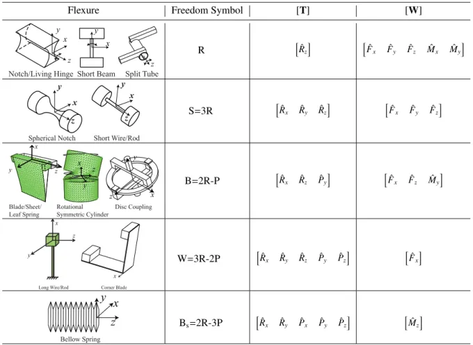
According to the mobility or the rank of their twist system, we can categorize the most commonly used flexure primi-tives as shown in Table 1.
1. A notch hinge, denoted by symbol “R”, allows a rota-tion about the centerline and constraints other morota-tions. The shape of the cross section may be circular, elliptical, hyperbolic etc. Meanwhile short beams, living hinges that have one dimension significantly smaller than oth-ers can function as a notch hinge. A split tube which is a tube sliced along its longitudinal direction also allows a single rotation about its axis. If we define the axis of the R-joint to be the z-axis, its twist and wrench matrices can be written as
[Tr]=
h
ˆ
Rz
i
, [Wr]=
h
ˆ
Fx Fˆy Fˆz Mˆx Mˆy
i
(12)
2. A spherical notch or short wires/rod, denoted by “S”, allows three rotations and constrains three translations. Kinematically it is equivalent to a serial chain of three R-joints, i.e. S=3R. Their twist and wrench matrices are
[Ts]=
h
ˆ
Rx Rˆy Rˆz
i
, [Ws]=
h
ˆ
Fx Fˆy Fˆz
i
(13)
3. Blade/sheet flexures also called leaf springs, denoted by “B”, allow two rotations and one translation, i.e. B=2R−P. The rotational symmetric cylinders and disc rings also have the same freedom and constraint spaces. As shown in Table 1, we define the normal of the blade as the y-axis and the longitudinal direction being the x-axis. The two rotations are about two in-plane axes (x,z) due to beam torsion and beam bending
respec-tively. And the translation is along the normal direction
y, caused by beam bending. From the constraint point of view, a blade removes one rotation and two translations. Their twist and wrench matrices are
[Tb]=
h
ˆ
Rx Rˆz Pˆy
i
, [Wb]=
h
ˆ
Fx Fˆz Mˆy
i
(14)
4. A long wire/rod flexure, denoted by “W”, removes the translation along its axis and allows the other five mo-tions. A corner blade (a folded sheet) also provides a single constraint along its fold line. Their freedom space is equivalent to three R-joints and two P-joints, i.e. W=3R-2P. Mathematically its corresponding twist and wrench matrices are
[Tw]=
h
ˆ
Rx Rˆy Rˆz Pˆy Pˆz
i
, [Ww]=
h
ˆ
Fx
i
(15)
5. And lastly, a bellow spring, denoted by “Bs”, removes a single rotation along its axis with a freedom space de-noted by Bs=2R-3P. Its twist and wrench matrices are
[Tbs]=hRˆx Rˆy Pˆx Pˆy Pˆz
i
, [Wbs]=
h
ˆ
Mz
i
(16)
Table 1 summarizes the aforementioned flexure primitives and their freedom space and twist and wrench matrices. These primitives are basic building blocks for constructing more complex flexure systems.
3.2 Serial chains of flexure primitives
The freedom space of a rigid body represents all of its al-lowable motion in space. For any given flexure element or building block, its freedom space is a f system that is repre-sented by a twist matrix [T] formed by f independent twists, written as
[T]=hTˆ1 Tˆ2 · · ·Tˆf
i
(17)
When a mechanism is formed by mflexure elements or building blocks that are connected in serial, its twist ma-trix (freedom space) can be obtained by combining the twist matrix of each building block column-wise, mathematically written as
[T]=[Ad1T1 Ad2T2 · · · AdmTm] (18)
where [Adj] represent the coordinate transformation from the j-th building block to the functional stage, defined in (9). This formulation has been previously presented by Su (2011). Also see similar work by Hopkins (2007b); Hopkins and Culpepper (2011).
Table 1.The motion and constraint spaces of commonly used flexure primitives.
Flexure Freedom Symbol [T] [W]
z
Notch/Living Hinge Split Tube
z y
x y
x
Short Beam
R hRˆz
i h
ˆ
Fx Fˆy Fˆz Mˆx Mˆy
i
y
x
z
y x
z
Spherical Notch Short Wire/Rod
S=3R hRˆx Rˆy Rˆz
i h
ˆ
Fx Fˆy Fˆz
i
z y
x
Blade/Sheet/ Leaf Spring
z
y x
Rotational Symmetric Cylinder
Disc Coupling
z y
x
B=2R-P hRˆx Rˆz Pˆy
i h
ˆ
Fx Fˆz Mˆy
i
x
y
z
Long Wire/Rod Corner Blade x
W=3R-2P hRˆx Rˆy Rˆz Pˆy Pˆz
i h
ˆ Fx
i
z
y
x
Bellow Spring
Bs=2R-3P hRˆx Rˆy Pˆx Pˆy Pˆz
i h
ˆ Mz
i
The transformation from one basis to another is done by a linear operation to the twist matrix.
A freedom space can be spanned by different sets of basis twists. This can be very useful in design practices. For in-stance, consider a freedom space formed by rotations about two parallel axes. The twist matrix of these two rotations is
[T]=hTˆR1 TˆR2
i
=
"
Ω Ω
c1×Ω c2×Ω
#
(19)
Subtracting the second column from the first one yields
[T]
"
Ω 0
c1×Ω (c2−c1)×Ω
#
(20)
whererepresents a column-wise linear operation. Note the
second column of the above matrix represents a translation along the direction normal to both the rotation axis and the linec1c2. Basically this means that a serial chain of two rota-tions is equivalent to a serial chain of a rotation and a trans-lation. See the top part of Fig. 1.
Similarly, a serial chain of three (non-coplanar) parallel ro-tations is equivalent to a rotation plus two orthogonal
trans-lations. They are formulated in screws as
[T] = hTˆR1TˆR2 TˆR3
i
=
"
Ω Ω Ω
c1×Ω c2×Ω c3×Ω
#
(21)
"
Ω 0 0
c1×Ω (c2−c1)×Ω (c3−c1)×Ω
#
, (22)
where the second and third columns represent translations. See the bottom part of Fig. 1 for illustration of this case.
3.3 Parallel chains of flexure primitives
The constraint space of a rigid body represents all the forbid-den motions of the body subject to a constraint arrangement. In screw theory, a constraint space can be represented by a wrench matrix [W] combined by cindependent wrenches, written as
[W]=hWˆ1 Wˆ2 · · · Wˆc
i
(23)
The constraint space of a flexure mechanism formed bym
building blocks connected in parallel is given by a wrench matrix that is obtained by assembling the wrench matrix of each building block, written as
1
c c2
1
R R2
P
1
c
2
c
3
c
1
R R2
2
P
3
R
1
P
Figure 1.Equivalent freedom spaces. (Top) A serial chain of two parallel rotations produces a translation. (Bottom) A serial chain of three (non-coplanar) parallel rotations produce two translation.
Again, matrices [Adj] represent the coordinate transforma-tion from j-th building block to the functional stage.
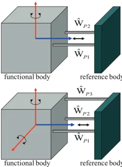
Similar to serial chains of flexures, the constraint space of two parallel translational constraints assembled in parallel (Fig. 2) is represented by two force wrenches with identical directionF
[W]=hWˆP1 WˆP2
i
=
"
F F
c1×F c2×F
#
(25)
Subtracting the second column from the first one yields
[W]=
"
F 0
c1×F (c2−c1)×F
#
(26)
Note the second column of the above matrix represents a ro-tational constraint along the direction perpendicular to both the constraint axisFand the linec1c2. Basically this says that a parallel chain of two translational constraints removes one rotation and one translation.
And a parallel chain of three (non-coplanar) parallel trans-lational constraints removes two rotations and one transla-tion. This is illustrated with the following mathematical for-mulation
[W]=hWˆP1WˆP2WˆP3
i
=
"
FFF c1×Fc2×Fc3×F
#
(27)
"
F00
c1×F(c2−c1)×F(c3−c1)×F
#
(28)
4 Synthesis of freedom elements
In this section, we use flexure primitives listed in Table 1 to design flexure joints that have only one DOF, rotational (R) or translational (P). To design freedom elements, we use parallel chains of primitives to remove unwanted freedoms.
reference body functional body
1
W
ˆ
Preference body functional body
2
W
ˆ
P1
W
ˆ
P2
W
ˆ
P3
W
ˆ
PFigure 2.Equivalent constraint spaces. (Top) A parallel chain of two parallel translational constraints exerts a translational plus a ro-tational constraint to the functional body. (Bottom) A parallel chain of three (non-coplanar) parallel translational constraints exerts a translation plus two rotational constraints. The arrows represent the removed motions.
4.1 Synthesis of R-jointsTˆR
The freedom space of an R-joint is given by ˆTR shown in (4). Without loss of generality, we assume the axis of R-joint through the origin, i.e.c=(0,0,0)T. This gives us
ˆ
TR=
(
Ω
0
)
(29)
Our goal is to remove the other five unwanted motions: two rotations and three translations. Since we consider paral-lel structures of at least two limbs and each limb must apply 1–5 constraints to the functional body, primitive “R” (notch hinge) cannot be used in the design as it is indeed a R-joint. This leads us total 11 possible combinations with the other four primitives B, S, W and Bs. Among them, cases 1-5 use no bellow springs and cases 6–11 use at least one bellow spring.
Use flexure primitives B and W only
The first three cases concerns designs with primitives B and W only: 2B, B-2W, 5W. These are the most commonly used designs.
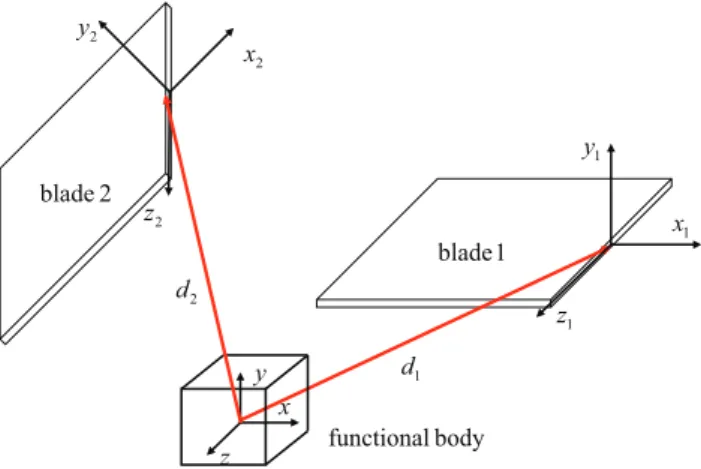
4.1.1 Case 1: 2B
x y
z
1
x
1
d
1
y
1
z
2
x
2
y
2
z
2
d 2 blade
1 blade
body functional
Figure 3.Synthesis of R-joints with a parallel connection of two blades. The two blades are rigidly connected to the functional body.
coordinate transformation of two blades relative to the func-tional body by [Ad1] and [Ad2] which are the six by six ad-joint matrices with the form of (9). By applying the coordi-nate transformation to both blades, their wrench matrices are calculated by (10,11) as
[Wi]=[Adi][Wb]=
"
xi zi 0
di×xi di×zi yi
#
, i=1,2, (30)
where [Wb] is the wrench matrix of blade written in (14). And vectorsxi,yi,zi,didenote the orientation and position of
i-th blade.
Requiring the reciprocity of the [Wi] with ˆTR yields the necessary condonations regarding to the orientation and po-sition of the blades
Ω·(di×xi) = 0, =⇒ xi·(di×Ω)=0 (31) Ω·(di×zi) = 0, =⇒ zi·(di×Ω)=0 (32)
Ω·yi = 0. (33)
Simplifying the first two conditions yields
di·yi=0, Ω·yi = 0. (34)
The first equality is interpreted as that the translationdimust in the blade planexizi. The second condition means thatyi, the normal direction of the blade, must be perpendicular to the axis of the R-joint (Ω). IfΩ=(1,0,0)T,yimust be in the planeyzof the functional body. Picking any two independent directions in theyzplane leads us a solution, e.g.
y1=(0,1,0) T
, y2=(0,0,1) T
(35)
Onceyi is determined. The axes ofxiandzi are chosen ar-bitrarily as long as the two blades are not co-planar (redun-dant).
Depending on how xi and zi are chosen for each blade, we can obtain three possible designs. Ifz1=z2=(1,0,0)T,
we have a design with both blades subject to bending, shown
in Fig. 4a. This is the most often used flexure hinge design. Ifx1=z2=(1,0,0)T, we have a design with blade 1 subject
to twisting and blade 2 subject to bending, Fig. 4b. Ifx1=
x2=(1,0,0)T, we have a design with both blades subject to
twisting, Fig. 4c.
4.1.2 Case 2: B-2W
This design evolves from the case 2B. Since a blade allows two rotations and one translation, we just need to remove one rotation and one translation with two wires. We have shown in (27) that two parallel constraints remove one translation and one rotation. Therefore, replacing one blade of the 2B design with two parallel wires yields a B-2W design, shown in Fig. 4d.
4.1.3 Case 3: 5W
In order to obtain a hinge design with five wires, we simply replace the blade of the B-2W design with three co-planar wires. This is due to the fact that a blade is equivalent to three co-planar wires. See Fig. 4e. An alternative synthesis procedure using screw algebra for the case five wires can be found in Su and Tari (2010).
Use flexure primitives S, B, W
Now we consider designs using primitives S, B, W with at least one S-joint. There are three possible combinations: 2S, S-2W, B-S.
However the case B-S is not qualified as a R-joint for the following reasons. Without loss of generality, we let the co-ordinate system align with the local coco-ordinate system of the blade shown in Table 1. And we denote the position of S-joint byd=(dx,dy,dz)T. Therefore the wrench matrix of the blade and the S-joint are
[Wb]=
h
ˆ
Rx Rˆz Pˆy
i
,[W′s]=
"
i j k
d×i d×j d×k
#
(36)
where vectorsi,j,k are unit vectors along three coordinate
axes. And [W′
s] is the wrench matrix with an appropriate co-ordinate transformation, i.e. [W′
s]=[Ad][Ws]. We write the wrench matrix of the parallel structure B-S and apply a linear operation to obtain
[Wbs]=hWb W
′
s
i
=
1 0 0 1 0 0 0 0 0 0 1 0 0 1 0 0 0 1 0 0 0 0 −dz dy 0 0 1 dz 0 −dx 0 0 0 −dy dx 0
(a) (b) (c) (d) (e) (f)
(g) (h) (i) (j) (k) (l) (m)
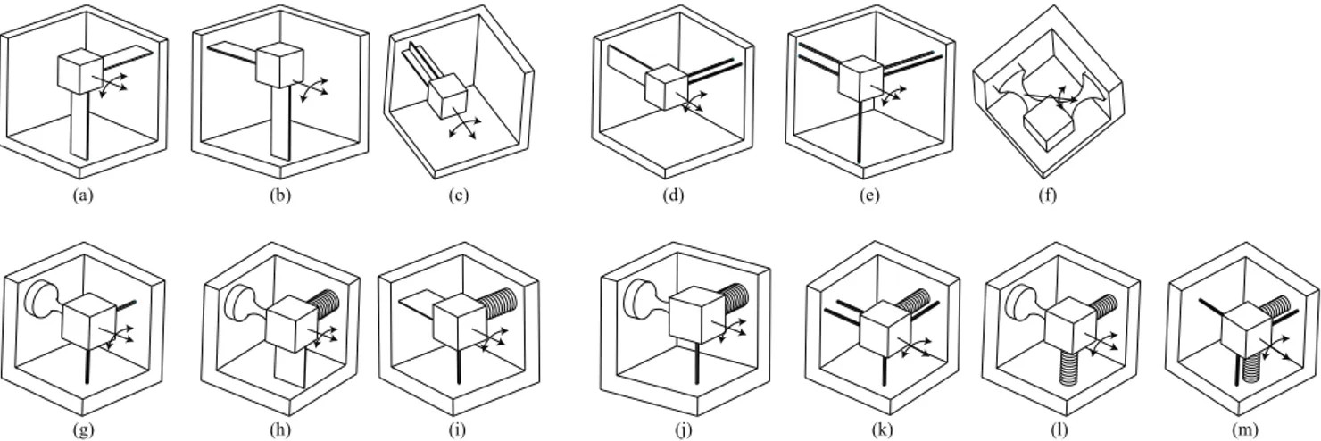
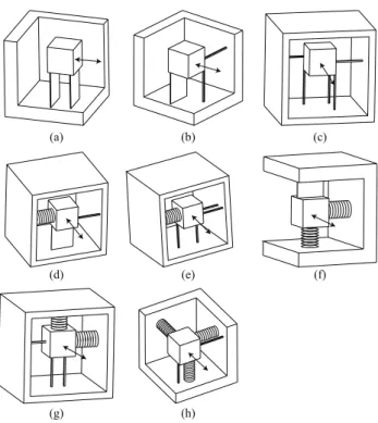
Figure 4.Various designs of R-joints with flexure primitives: B, W, S and Bs.(a–c)case 1 with two blades (BB).(d)case 2 with one blade
and two wires (B-2W).(e)case 3 with five wires (5W).(f)case 4 with two spherical notches (2S).(g)case 5 with one spherical notch with two wires (S-2W).(h)case 6 with one bellow spring, one blade and one spherical notch (Bs-B-S).(i)case 7 with one bellow spring, one
blade and one wire (Bs-B-W).(j)case 8 with one bellow spring, one spherical notch and one wire (Bs-S-W).(k)case 9 with one bellow
spring and four wires (Bs-4W).(l)case 10 with two bellow springs and one spherical notch (2Bs-S).(m)case 11 with two bellow springs
and three wires (2Bs-3W). The double arrow arcs represent the rotation allowed by flexure R-joints. The box represents the functional body.
1 0 0 0 0 0 0 0 0 0 1 0 0 1 0 0 0 0 0 0 0 0 −dz dy 0 0 1 0 0 0 0 0 0 −dy dx 0
(38)
From Eq. (38), we can draw two conclusions. (1) Ifdy,0, [Wbs] has a full rank which means that the body is fully con-strained by this structure. (2) Ifdy=0, i.e. the S-joint is on the blade plane, [Wbs] has a rank of 2 since the 4th and 6th column would be zeros. As a matter of fact, its reciprocal freedom space is formed by the two rotations allowed by the blade flexure. Therefore, parallel structures of B-S cannot form a R-joint design.
4.1.4 Case 4: 2S
The 2S case is trivial. When two S-joints are connected in parallel, this results in a single rotation about the line con-necting to their joint centers, Fig. 4f.
4.1.5 Case 5: S-2W
The case S-2W is synthesized as the following. The S-joint itself removes three translations. We just need to remove two additional rotations with two wire flexures. By using a wire parallel to y-axis with a non-zero offsetd=(d,0,0)T, the
ro-tation ˆRzis removed. Similarly, a wire parallel to z-axis with a non-zero offsetd=(d,0,0)Tremoves the rotation ˆRy. Math-ematically, the wrench matrix of S-joint and the two wires are
[Ws]=
1 0 0 0 1 0 0 0 1 0 0 0 0 0 0 0 0 0
, [W2w]=
0 0 1 0 0 1 0 0 0 −d
d 0 (39)
The constraint space of S-2W is obtained by combining [Ws] and [W2w], to which we apply a column-wise reduction and obtain
[Ws−2w]=
h
Ws W2w
i =
1 0 0 0 0 0 1 0 0 0 0 0 1 0 0 0 0 0 0 0 0 0 0 0 −d 0 0 0 d 0
(40)
Obviously its reciprocal twist matrix is ˆRxwhich corresponds to a single rotation about the x-axis. This design is shown in Fig. 4g.
Use flexure primitives Bs, S, B, W
4.1.6 Case 6: Bs-B-S:
From Eq. (38), we have concluded that a B-S parallel struc-ture may result in a freedom space of two rotations if the cen-ter of S-joint is on the blade plane. Now we just need to use a bellow spring Bsto remove one rotation in order to yield a freedom space of only one rotation, hence a hinge design in Fig. 4h.
4.1.7 Case 7: Bs-B-W:
As we know one blade has a freedom space of 2R-P. To ob-tain a single rotation, we can use a bellow spring to remove one rotation and a wire to remove the translation. See this design in Fig. 4i.
4.1.8 Case 8: Bs-S-W:
The S-joint has a freedom space of 3R. To obtain a single rotation, we can use a bellow spring to remove one rotation then use a wire offset to the center of the S-joint to remove the second rotation. This results a design shown in Fig. 4j.
4.1.9 Case 9: Bs-4W:
To synthesize this case, we first use three wires aligning the three coordinate axes to remove three translations. This leaves us three rotations. We then remove two more rotations by two more wires. By Eq. (26), we know that two parallel constraints remove one additional rotation. Therefore we let a fourth wire be parallel to one of the three wires aforemen-tioned. This fourth wire removes a rotation about the normal line to the plan formed by the two parallel wires. At last, a bellow spring is used to remove another rotation. This results a hinge design shown in Fig. 4k.
4.1.10 Cases 10: 2Bs-S
The synthesis of 2Bs-S case is simple. The S-joint removes three translations and two bellow springs remove two of the three rotations, Fig. 4l.
4.1.11 Cases 11: 2Bs-3W
This case is also trivial. First the three wires aligning the three coordinate axes remove three translations. And we then use two bellow springs remove two rotations. This design is shown in Fig. 4m.
4.2 Synthesis of P-JointsTˆP
Now let us synthesize P-joints with flexure primitives listed in Table 1. The freedom space of an P-joint is given by a single twist
ˆ
TP=
(
0 V
)
(41)
where vector V represent the translational direction of P-joint.
We are interested in simple parallel structures with at least two limbs that remove three rotations and two translations. And each limb must apply at least one constraint and allow at least one translational motion for the functional body. There-fore primitives “R” and “S” are not qualified as they allow no translation. This leaves three possible primitives: B, W and Bs from which we can have eight possible cases. Three of them use no bellow springs and the other five use at least one bellow spring.
Designs with flexures B, W only
Considering only flexure B and W, we have three cases: 2B, B-2W and 5W.
4.2.1 Case 1: 2B
For designs with two blades, the reciprocity conditions of ˆTP in (41) with the wrench matrices [Wi] in (30) yields
V·xi=0, V·zi=0, i=1,2 (42)
from which we conclude thatVmust be parallel to bothyi
(normal of the blade plane). This means that two blades must be parallel with the normal of the blade plane along the axis of P-joint. This is the well known parallel sheet design of P-joints shown in Fig. 5a.
4.2.2 Case 2: B-2W
The design with one blade and two wires can be easily ob-tained by replacing one blade with two wires that are parallel to the blade plane. Figure 5b.
4.2.3 Case 3: 5W
This design is obtained from the B-2W design by replacing one blade with three co-planar wires and the other one with two wires. This case can also be computationally synthesized with screw theory. Assume the P-joint is along the x direc-tion, i.e. V=(1,0,0)T. First of all, compute the reciprocal
wrench matrix of ˆPusing linear algebra as
[W]=
0 0 0 0 0 1 0 0 0 0 0 1 0 0 0 0 0 1 0 0 0 0 0 1 0 0 0 0 0 1
We then apply a column-wise linear operation to this wrench matrix to obtain
[W′
]=
0 0 0 0 0 1 1 0 0 1 0 0 1 1 0 0 0 0 0 1 0 0 0 1 0 0 1 0 0 0
(44)
Each column of [W′
] is a force wrench which can be realized with a long wire flexure (W). The 5W design is shown in Fig. 5b. See the work by Su and Tari (2010) for an alternative synthesis procedure for this case.
Designs with flexures B, W and Bs
There are five cases with at least one bellow spring: Bs-B-W, Bs-4Bs-B-W, 2Bs-B, 2Bs-3Bs-B-W, 3Bs-2W. We discuss each in the following.
4.2.4 Case 4: Bs-B-W
A blade B has a freedom space of 2R-P. To obtain a P-joint design, we must remove the two rotations. First we use a wire flexure with axis being parallel and has a non-zero distance to the blade plane to remove one rotation. The second rotation is removed by a bellow spring flexure. See Fig. 5d.
4.2.5 Case 5: Bs-4W
This design can be obtained from the case Bs-B-W by replac-ing the blade with three co-planar wires. A computational way to synthesize this case is applying an alternative lin-ear operation to the wrench matrix [W] in (43). This time we would like to have four force wrenches and one couple wrench. The new wrench matrix is written as
[W′′
]=
0 0 0 0 0 1 1 0 0 1 0 0 1 0 0 0 0 0 0 1 0 0 0 1 0 0 1 0 0 0
(45)
of which the fourth column is a couple wrench and the other four are force wrenches. Realizing each force wrench with a wire and the couple wrench with a bellow spring yields the design of Bs-4W. See Fig. 5e.
4.2.6 Case 6: 2Bs-B
This case is trivial since the two bellow springs remove the two rotations of the blade. This leaves a freedom space with a single translation, hence a P-joint design shown in Fig. 5f.
(a) (b) (c)
(d) (e) (f)
(g) (h)
Figure 5. Various designs of P-joints with parallel structures of flexure primitives: B, W, Bs. (a) case 1 with two blades (2B). (b)case 2 with one blade and two wires (B-2W).(c)case 3 with five wires.(d)case 4 with one bellow spring, one blade and one wire (Bs-B-W).(e)case 5 with one bellow spring and four wires
(Bs-4W).(f)case 6 with two bellow springs and one blade (2Bs
-B).(g)case 7 with two bellow springs and three wires (2Bs-3W). (h)case 8 with three bellow springs and two wires (3Bs-2W). The
arrowed lines indicate the direction of translation. The box repre-sents the functional body.
4.2.7 Case 7: 2Bs-3W
This case evolves from case 2Bs-B by replacing the blade with three co-planar wires. See Fig. 5g.
4.2.8 Case 8: 3Bs-2W
For this case, the 3 bellow springs remove three translations and two wires remove two translations. This design is shown in Fig. 5h.
5 Synthesis of constraint elements
5.1 Synthesis of P-constraintsWˆP
A P-constraint element removes a translational freedom of the functional body while allows all other motions. The con-straint space of the translational concon-straint is given by a pure force given in (5).Without loss of generality, we assume the axis of translational constraint through the origin of the co-ordinate system, i.e.c=(0,0,0)T. That is
ˆ
WP=
(
F 0
)
(46)
whose complementary freedom space consists of three rota-tions plus two translarota-tions, i.e. 3R-2P.
To synthesize the translational constraint ˆWP, we consider serial chains of at least two flexure primitives to make up the complementary freedom space of ˆWP. We do not include the long wire (W) flexure in the design as itself is indeed a trans-lational constraint. Also bellow springs (Bs) are not quali-fied either as they allow three translations. As a result, only three types of primitives S, B and R are considered in de-sign. Based on the degree of freedom, there are six possible combinations: S-S, S-B, S-2R, B-B, B-2R and 5R. However these primitives must satisfy some restriction on their rela-tive orientation and position. In what follows, we derive the geometric conditions for each case.
5.1.1 Case 1: S-S
By intuition, we know that a serial chain of two S-joints re-moves one translation along the line connecting the center of the joints. Here let us give a mathematical proof with screw theory. Without loss of generality, we assume one S-joint be-ing at the origin of the coordinate system and the other one being at a distance ofd along x-axis, i.e.d=(d,0,0)T. The
twist matrices of these two blades are
[T1]=
"
i j k
0 0 0
#
, [T2]=
"
i j k
d×i d×j d×k
#
(47)
By the formulation for serial structures in Eq.(18), the twist matrix of the S-S chain is written as
[T]=hT1 T2
i
=
"
i j k i j k
0 0 0 d×i d×j d×k
#
(48)
Substituting d=(d,0,0)T and subtracting the last three
columns from the first three columns yield
[T′
]=
"
i j k 0 0 0
0 0 0 0 dk −dj
#
(49)
which indicates three rotations and two translation along y-and z-axes, i.e. the translation along x-axis is removed. See Fig. 7a. The arrow line represents the removed translation.
x y
z
2
x
2
d
2
y
2
z
1
x
1
y
1
z
1
d
blade
body functional
spherical notch
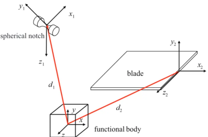
Figure 6.Synthesis of P-constraint with a serial chain of one blade (B) and one spherical notch (S). The blade is connected with the spherical notch via an intermediate body (not drawn)
5.1.2 Case 2: S-B
Figure 6 shows a serial chain of S and B flexures. Applying a general coordinate transformation to the twist matrices of the blade and the spherical notch in (13, 14) yields
[Ts] =
"
x1 y1 z1
d1×x1 d1×y1 d1×z1
#
, (50)
[Tb] =
"
x2 z2 0
d2×x2 d2×z2 y2
#
(51)
Since both freedom spaces are complementary to the pre-scribed translational constraint, ˆWP in (46) is reciprocal to both [Ts] and [Tb]. The reciprocity condition of S-joint leads to
F·(d1×x1)=0 =⇒ x1·(F×d1)=0 (52)
F·(d1×y1)=0 =⇒ y1·(F×d1)=0 (53)
F·(d1×z1)=0 =⇒ z1·(F×d1)=0 (54)
which are reduced to
F×d1=0, =⇒ d1=d1F (55)
This implies that the position of the S-joint must be along the direction ofF.
And the reciprocity requirement for the blade leads to
F·(d2×x2) = 0 =⇒ x2·(F×d2)=0 (56)
F·(d2×z2) = 0 =⇒ z2·(F×d2)=0 (57)
F·y2 = 0 (58)
which are reduced to
F×d2=d2y2, F·y2=0 (59)
Substituting (55) into (59) yields
The first equality implies that the spherical notch must be on the blade plane. And the second equality means that the normal of the blade must be perpendicular to the direction of
F. The design is shown in Fig. 7b.
5.1.3 Case 3: S-2R
For this design case, we first recognize that an S-joint pro-vides three rotations (3R). We just need to make up two more translations with two notch hinges (R). We have shown in Sect. 3.2 that two parallel rotations produce a translation and three parallel rotations produce two translations. Therefore we can have two possible designs. One design utilizes two perpendicular R-joints. Each R-joint is parallel to one ro-tation axis of the S-joint. The direction of the translational constraint is along the direction that is perpendicular to both R-joint axes. See Fig. 7c.
The other design uses two parallel R-joints which together with one rotation of the S-joint produce two translations. The S-joint and two R-joints axes are co-planar. The direction of the translational constraint is parallel to the R-join axis. And the constraint line passes through the center of S-joint. See Fig. 7d. Note the functional body cannot translate along the direction indicated with its orientation fixed.
5.1.4 Case 4: B-B
The synthesis of B-B follows a similar procedure of the case S-B. For this case, both blades must satisfy the conditions in Eq. (59), i.e.
d1=d1y1×F, F·y1=0 (61)
d2=d2y2×F, F·y2=0 (62)
where we have applied a vector algebra operation. This means that the normal of both blades must be perpendicular to the directionF. However the two blades must not be paral-lel to each other as otherwise they would be redundant. The intersection line of the blades is the constraint line. Depend-ing on how the blades are oriented, we can have two possible designs. In the design shown in Fig. 7e, the constraint line is along the longitude direction of the blades. And in the de-sign shown in Fig. 7f, the constraint line is along the width direction of the blades.
5.1.5 Case 5: B-2R
Since a blade has two rotations and one translation, we can make up one rotation and one translation with two R-joints. Obviously one R-joint must be along the normal of the blade plane in order to make up the third rotation. The second R-joint is parallel to the first R-R-joint. These two parallel R-R-joints produce one additional translation along the local z-axis of the blade. See Fig. 7g.
(a)
(b)
(c)
(e)
(f)
(g)
(h)
(d)
(i)
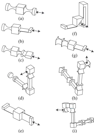
Figure 7.Various designs of P-constraint ˆWPwith serial chains of
flexure primitives S, B and R. The double head arrows represent the direction of the constrained translation. One end of the chains is fixed.(a)case 1 with two spherical notches (2S).(b)case 2 with one spherical notch and one blade (S-B).(c–d)case 3 with one spherical notch and two notch hinges (S-2R).(e–f)case 4 with two intersect-ing blades (2B).(g)case 5 with one blade and two notch hinges (B-2R).(h–i)case 6 with five notch hinges (5R).
5.1.6 Case 6: 5R
Synthesis of this case is simple. To produce two translations with a serial chain of 5R, we can have two possible designs by using parallel rotations. In one design, we have two R-joints parallel to one plane and another two R-R-joints parallel to a second plane. This design takes advantage of the fact that two parallel rotations produce a translation as proven previ-ously. The direction of the translational constraint is along. See Fig. 7h.
And the other design uses three parallel R-joints which produce two translations in the plane normal to the axis of the R-joints. The direction of the translational constraint is along the the axis of the three parallel R-joints. See Fig. 7i.
5.2 Synthesis of R-ConstraintsWˆR
constraint is pure couple wrench ˆWRgiven in (5), which we copy here for convenience
ˆ
WR=
(
0 M
)
(63)
Our goal is to use serial chains of at least two flexure prim-itives to design ˆWR. That is to make up its complementary freedom space which consists of two rotations (R) and three translations (P). Since a bellow spring is itself a rotational constraint, we do not consider it in our design. And wires and spherical notches are also excluded in design as their freedom space already consists of three rotations. Therefore we only consider primitives B and R. There are three poten-tial designs B-B, B-2R and 5R.
5.2.1 Case 1: B-B
To synthesize a serial chain of B-B for a rotational constraint, we first write the twist matrix of the blades as
[Ti]=
"
xi zi 0
di×xi di×zi yi
#
, i=1,2 (64)
They must be reciprocal to ˆWRin (63). This leads us the fol-lowing necessary conditions
M·xi=0, M·zi=0 (65)
which implies that
y1=y2=M (66)
Therefore, we conclude that two blades must be parallel to each other with their y-(normal) axis alongM. The two par-allel blades must be separated by a nonzero distance in order to produce sufficient translations in three directions. This de-sign is shown in Fig. 8a.
5.2.2 Case 2: B-2R
Tee design of B-2R is synthesized as the following. The B flexure has a freedom space of 2P. We have to use two R-joints to make up two extra translations. And the two transla-tions must be in the blade plane. The only solution is to have one R-joint parallel to the bending direction of the blade and the other R-joint parallel the torsion direction of the blade. And they should be separated by nonzero distance. This de-sign is shown in Fig 8b.
5.2.3 Case 3: 5R
This case is trivial as there is only one possible design. That is, three R-joints are parallel to one plane and the other two R-joints parallel to a second plane. And these two planes are perpendicular to each other. See Fig. 8c.
(a)
(b)
(c)
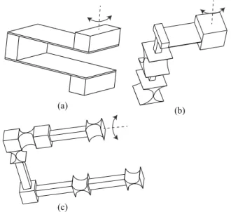
Figure 8.Various designs of the rotational constraint ˆWRwith serial
chains of flexure primitives B and R. The arrowed arcs represent the rotation constrained by the flexure design. One end of the chains is fixed.
6 Synthesis of hybrid structures
We can build more complex flexure mechanisms with hy-brid structures of flexure primitives together with the free-dom and constraint elements synthesized in the previous sec-tions. Here a hybrid structure is a structure with both serial and parallel connections. As a matter of fact, many spatial flexure mechanisms in practice are in hybrid structures (Yao et al., 2008; Dong et al., 2008). In this section, we use four examples to demonstrate how to design hybrid structures.
6.1 Hybrid designs of joints and constraints
(a) (b) (c)
Figure 9.Designs of P-joints with hybrid structures.
A
B
Figure 10.A serial chain of three P-joints connected with two in-termediate bodies. Each P-joint is a parallel blade design shown in Fig. 5a. Body B is the fixed base. Body A is the functional body. The arrow lines represent three translations along three coordinate axes.
formed by two identical limbs assembled in parallel. Each limb is a serial chain of two R-joints. It is not hard to prove that this hybrid structure allows only one translation indi-cated in the figure. If we replace one of the RR chain with a blade flexure, we obtain another design shown in Fig. 9b. And Fig. 9c shows a double parallelogram design that is formed by a serial connection of two parallelogram 4-bar de-sign. This design is widely used to reduce parasitic errors and increase the displacement stroke.
6.2 Synthesis of serial chains with freedom elements As we discussed previously, we can use a serial chain of R-joints and P-joints to construct a freedom space with any combination of DOF. For instance, a serial chain of three P-joints can make up a freedom space of three translations. If we use the double parallel flexure structure for the P-joint design, we obtain a serial PPP design with three decoupled translations. See Fig. 10. Of course, one can further increase the structural stiffness with assembling multiple serial chains of PPP in parallel (Awtar et al., 2011).
B
B
B
A
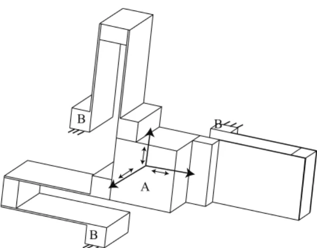
Figure 11.A parallel kinematic chain of three translational con-straints results in a design with three rotations about the center of the functional body A. The body B are fixed.
6.3 Synthesis of parallel chains with constraint elements
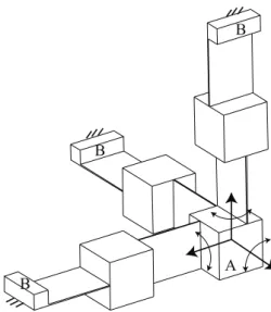
In duality, one can also synthesize parallel chains with the constraint elements synthesized in the previous sections. For instance, if we would like to design a parallel structure with three rotations, we just need to use three translational con-straint elements to remove all translations. If we choose the BB design in Fig. 7e for all three translational constraints, we obtain the design shown in Fig. 11. The functional body A can rotate about its center relative to the base body B while its translations are constrained.
As another example, we would like to design a parallel structure with three translations. We just need to use three rotational constraint elements to remove all rotations. If we choose the BB design in Fig. 8a for all three rotational con-straints, we obtain the design shown in Fig. 12. The func-tional body A can translate in all directions while its rotations are constrained.
7 Conclusions
B
B B
A
Figure 12.A parallel kinematic chain of three rotational constraints result in a design with three translations along the direction indi-cated in the figure. The body B are fixed. The body A is the func-tional body.
type synthesis (type/toplogy selection) of flexure mecha-nisms which has been an ad hoc process. It also paves the way towards to design automation and systematic invention of new flexure machinery.
Acknowledgements. This material is based upon work sup-ported by the National Science Foundation under Grant No: CMMI-1161841. Any opinions, findings, and conclusions or recommendations expressed in this material are those of the author(s) and do not necessarily reflect the views of the National Science Foundation.
Edited by: G. Hao
Reviewed by: two anonymous referees
References
Awtar, S. and Slocum, A. H.: Constraint-based design of parallel kinematic xy flexure mechanisms, J. Mech. Des.-T. ASME, 129, 816–830, 2007.
Awtar, S., Ustick, J., and Sen, S.: An XYZ Parallel Kinematic Flex-ure MechanismWith Geometrically Decoupled Degrees of Free-dom, ASME Journal of Mechanisms and Robotics, 5, 119–126, 2011.
Ball, R. S.: The Theory of Screws, Cambridge University Press, Cambridge, England (Originally published in 1876 and revised by the author in 1900, now reprinted with an introduction by H. Lipkin and J. Duffy), 1998.
Blanding, D. L.: Exact Constraint: Machine Design Using Kine-matic Processing, ASME Press, New York, NY, 1999.
Brouwer, D., de Jong, B., and Soemers, H.: Design and modeling of a six DOFs MEMS-based precision manipulator, Precis. Eng., 34, 307–319, 2010.
Chen, S.-C. and Culpepper, M. L.: Design of a six-axis micro-scale nanopositioner-µHexFlex, Precis. Eng., 30, 314–324, 2006.
Culpepper, M. L. and Anderson, G.: Design of a low-cost nano-manipulator which utilizes a monolithic, spatial compliant mech-anism, Precis. Eng., 28, 469–482, 2004.
Dai, J. S. and Jones, J. R.: Interrelationship between screw systems and corresponding reciprocal systems and applications, Mech. Mach. Theory, 36, 633–651, 2001.
Dai, J. S. and Jones, J. R.: A Linear Algebraic Procedure in Ob-taining Reciprocal Screw Systems, J. Robot. Syst., 20, 401–412, 2003.
Davidson, J. K. and Hunt, K. H.: Robots and Screw Theory: Appli-cations of Kinematics and Statics to Robotics, Oxford University Press, New York, NY, 2004.
Dong, J., Yao, Q., and Ferreira, P. M.: A novel parallel-kinematics mechanism for integrated, multi-axis nanopositioning: Part 2: Dynamics, control and performance analysis, Precis. Eng., 32, 20–33, 2008.
Hale, L. C.: Principles and Techniques for Designing Precision Ma-chines, Ph.D. thesis, MIT, Cambridge, MA, 1999.
Henein, S.: Flexures: simply subtle, tutorial on the design of flexure-mechanisms, Second International Symposium on Compliant Mechanisms, IFToMM/ASME CoMe 2011, delft, the Nether-lands, 2011.
Hopkins, J.: Modeling and Generating New Flexure Constraint El-ements, in: Proc. of the 12th EUSPEN International Conference, 424–428, Stockholm, Sweden, 2012.
Hopkins, J. B.: Design of parallel flexure systems via freedom and constraint topologies (FACT), MS, Massachusetts Institute of Technology, Cambridge, MA, 2007a.
Hopkins, J. B.: Design of flexure-based motion stages for mecha-tronic systems via freedom, actuation and constraint topologies (FACT), Ph.D. thesis, Massachusetts Institute of Technology, Cambridge, MA, 2007b.
Hopkins, J. B. and Culpepper, M. L.: Synthesis of multi-degree of freedom, parallel flexure system concepts via Freedom and Con-straint Topology (FACT) – Part I: Principles, Precis. Eng., 34, 259–270, 2010a.
Hopkins, J. B. and Culpepper, M. L.: Synthesis of multi-degree of freedom, parallel flexure system concepts via freedom and con-straint topology (FACT). Part II: Practice, Precis. Eng., 34, 271– 278, 2010b.
Hopkins, J. B. and Culpepper, M. L.: A screw theory basis for quan-titative and graphical design tools that define layout of actuators to minimize parasitic errors in parallel flexure systems, Precis. Eng., 34, 767–776, 2010c.
Hopkins, J. B. and Culpepper, M. L.: Synthesis of precision serial flexure systems using freedom and constraint topologies (FACT), Precis. Eng., 35, 638–649, 2011.
Howell, L. L.: Compliant Mechanisms, Wiley-Interscience, New York, NY, 2001.
Huang, Z., Liu, J., and Zeng, D.: A general methodology for mo-bility analysis of mechanisms based on constraint screw theory, Science in China Series E: Technological Sciences, 52, 1337– 1347, 2008.
Hunt, K. H.: Kinematic Geometry of Mechanisms, Oxford Univer-sity Press, New York, NY, 1978.
Phillips, J.: Freedom in Machinery. Volume 1, Introducing Screw Theory, Cambridge University Press, Cambridge, UK, 1984. Phillips, J.: Freedom in Machinery. Volume 2, Screw Theory
Exem-plified, Cambridge University Press, Cambridge, UK, 1990. Smith, S. and Chetwynd, D.: Foundations of Ultra-Precision
Mech-anism Design, CRC Press LLC, 1992.
Smith, S. T.: Flexure: Element of Elastic Mechanisms, CRC Press LLC, London, UK, 2000.
Su, H.-J.: Mobility Analysis of Flexure Mechanisms via Screw Al-gebra, ASME Journal of Mechanisms and Robotics, 3, 041010, doi:10.1115/1.4004910, 2011.
Su, H.-J. and Tari, H.: Realizing Orthogonal Motions With Wire Flexures Connected in Parallel, J. Mech. Des.-T. ASME , 132, 121002, doi:10.1115/1.4002837, 2010.
Su, H.-J. and Tari, H.: On Line Screw Systems and Their Appli-cation to Flexure Synthesis, ASME Journal of Mechanisms and Robotics, 3, 011009, doi:10.1115/1.4003078, 2011.
Su, H.-J., Dorozhkin, D. V., and Vance, J. M.: A Screw Theory Ap-proach for the Conceptual Design of Flexible Joints for Compli-ant Mechanisms, ASME Journal of Mechanisms and Robotics, 1, 041 009.1–041 009.8, 2009.
Varadarajan, K. M. and Culpepper, M. L.: A dual-purpose positioner-fixture for precision six-axis positioning and precision fixturing: Part I. Modeling and design, Precis. Eng., 31, 276–286, 2007a.
Varadarajan, K. M. and Culpepper, M. L.: A dual-purpose positioner-fixture for precision six-axis positioning and precision fixturing: Part II. Characterization and calibration, Precis. Eng., 31, 287–292, 2007b.
Yao, Q., Dong, J., and Ferreira, P. M.: A novel parallel-kinematics mechanisms for integrated, multi-axis nanopositioning: Part 1. Kinematics and design for fabrication, Precis. Eng., 32, 7–19, 2008.