WIND DRIVEN MOBILE CHARGING
OF AUTOMOBILE BATTERY
DR S.N. SINGH
Electronics & Communication Engineering
National Institute of Technology, Jamshedpur (India) - 831014
SUMIT KUMAR JHA
Electronics & Communication Engineering
National Institute of Technology, Jamshedpur (India) – 831014
SUDHIR KUMAR SINHA
Electronics & Communication Engineering
National Institute of Technology, Jamshedpur (India) – 831014
Abstract:
This paper deals with implementation of mobile wind driven generator technology to produce electricity in charging of two wheeler (12V) automobile battery. The use of PWM methodology with pulse charging method at a constant rate has been adopted for this purpose. The low speed PMSG driven by wind at speed of 15/40 km/hour has been used to eliminate gear box to achieve high efficiency. The output of three phase bridge rectifier is fed to boost converter which provides pulses of constant current to the battery.
Keywords: Permanent Magnet Synchronous Generator, Wind Energy, Pulse width modulation PWM etc.
1. INTRODUCTION
With the population explosion, exploitation of natural resources is heading towards its peak. Some projections indicate that the global energy demand will almost triple by 2050 and oil can only supply the world for up to 150 years [1]. Keeping these facts in mind, science has started emphasising upon sustainable development and has come up with advanced methods of energy conservation. We have developed different technologies for utilization of renewable resources of energy and these technologies are also being implemented in almost all sectors. Whether it is power generation by hydro projects or use of large scale solar panels, these technologies are being used at an extensive scale.
Today, with the advancement of technology in automobile sector, a large range of automobiles are being produced which run on battery. Apart from being cost effective, these vehicles are also eco-friendly as they don’t emit harmful gases. . The batteries used in these vehicles are generally lead-acid battery or Ni-MH SMF batteries. These batteries have to be charged for few hours and then they act as a source of energy for driving these vehicles. This technology is really appreciable but the snag in this technology is that battery has to be charged at some station before using it in vehicle and during this period, vehicle cannot move. The time taken for charging these batteries is about 4-8 hours, depending upon their charge condition. So, it is a considerable period of time during which vehicle has to be immobile. Also, while travelling if the battery gets discharged, then it can create a huge problem. The condition can get even worse if there is no nearby charging station.
In order to overcome these problems, investigation has been carried out with two wheeler scooter and we come upon with a proposal of maintaining sustainability of energy stored in the battery by “Wind Driven Mobile Battery Charger”. This system is based upon first law of thermodynamics and utilizes the concept of wind generator for generation of electrical energy which can be used to charge the battery used in vehicle.
The proposed model consists of three individual components namely wind-gen, PWM charge controller and battery as shown in Fig.1.
1.1. Mobile Wind Driven Generator
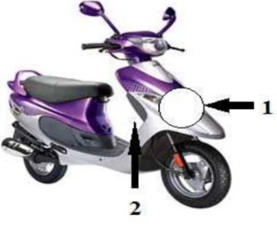
This block consists of wind gen which is installed in the front portion of the vehicle. The wind generator can be installed as shown in Fig.2 in the area pointed by the arrow 1. The PM generator and the circuit can be placed at the position pointed by the arrow 2.
Fig 2: Wind generator attachment at position 1 and 2 to Two wheeler automobile (Scooter)
The wind-gen can be attached externally in such a way that it becomes a part of the body of the scooter. It shouldn’t affect the area acquired by the scooter. The diameter of the fans shouldn’t be more than the width of the front portion of the vehicle. Proper care should be taken to provide rigidity to the wind generator.
The axle of fan system (wind-gen) is fixed to the shaft of the PM generator. The rotations of fans are responsible for rotating the shaft of the generator which in turn produces electrical energy.
1.2.Charge Controller
There are two conventional methods of charging a battery Constant Voltage charging method (CV)
Constant Current charging method (CC)
In the first method, a constant voltage is maintained across the battery load and the current passing through it may vary from boost (high) level to trickle (low) level.
In the latter method, current passing through the battery is held constant. The voltage across the battery may vary depending upon the percentage of charging. The voltage of the battery is minimum when it is completely discharged. As the battery starts getting charged, the voltage starts increasing and it becomes maximum when the battery is fully charged. Constant Current (CC) method is more efficient than Constant Voltage (CV) method.
1.3. Battery
The battery generally used to run a vehicle is either lead-acid or Ni-MH batteries. Battery used in two wheelers has specification of 12V, 36 Ah.
2. WIND ENERGY CONVERSION
rotation of blades causes rotation of the shaft of the alternator. In this system, there are two stages of energy transformation. In the first stage wind energy is being transformed into mechanical energy, as a result of which fans get rotated. In the second stage mechanical energy gets transformed into electrical energy which produces current.
Power generated by wind- gen depends upon these three factors: a) Air density, C.
b) Area swept by the fan, A. c) Velocity of the wind, v.
Power produced by a wind-gen depends directly upon the density of the wind. The density of wind may vary from place to place. It may have higher values in coastal areas where air has higher moisture content and it may be less in dry places like deserts. On an average the value of air density is around 1.23 Kg/m3.
It has been found that power output is directly proportional to the area swept by the fans. Also, the area swept by the fans is proportional to the square of length of the fans. So, fans of greater diameter are preferred. But there are certain limitations to the dimension of the fans. Larger fans may unbalance the system on which they have been installed. They may make the system bulkier which may create huge problem in their rotation.
Experimentally, it has been investigated that as the wind velocity gets doubled, the output power increases by eight times. So, it can be easily concluded that power output is proportional to cube of the wind velocity [4].
Power output is expressed by Eq. (1)
P = (1/2) C A v3
Eq. (1) The wind turbine torque (T) can be calculated from the equation (2) of power.
T = P / ω.
= (½) CA (v3/ω) Eq. (2)
In 1919, a scientist named Betz calculated that there’s a limit to how much power a turbine blade can extract from the wind. Beyond the Betz Limit of 59.26 % energy extraction, more and more air tends to go around the turbine rather than through it, with air pooling up in front. Hence, 59.26 % is the absolute maximum that can be extracted from the available power.
3. SYSTEM CONFIGURATION
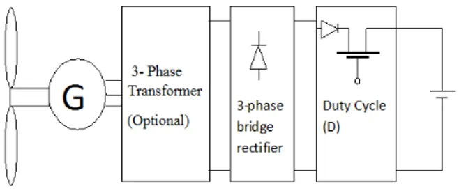
Power module contains 3- phase Transformer, a charging unit and Battery, as shown in Fig 2.
Fig 3: Power module of Battery Charger
3.1.PM Generator
The 24V generator used in this system is Permanent Magnet Synchronous Generator (PMSG) [2][3]. The term permanent magnet machine is used to include all electromagnetic energy conversion devices in which the magnetic excitation is supplied by a permanent magnet. The stator of the machine is identical to the stator of a multiphase AC machine. The new component is the rotor, which in contrast to conventional rotors relies on permanent magnets as the source of excitation rather than an electric current in windings. PMSG is based upon following Eq. (3), Eq. (4) and Eq. (5)
.
Where,
E is no load voltage of generator.
T = KIa.. Eq. (4) Where,
Ia is active part of generator current.
L (di/dt) = E -U – R I. Eq. (5) Where,
L, R: inductance and reactance of winding. U: generator voltage.
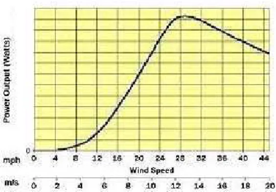
The PM machines can be of exterior type or interior type. Exterior types are mounted externally whereas interior types are mounted internally. In buried or interior PM machines, the machine is robust, rugged and well-suited for flux weakening control for a wide speed-torque range. The rotor structure for an interior PM rotor will tend to have a smooth rotor design similar to or better than induction machines. Thus, windage losses will be equal to or lower than those of conventional induction machines. The wind speed vs. voltage generated output of wind generator is shown in Fig.4.
Fig 4: Output voltage vs. wind speed
3.2.Transformer
Transformer is an electrostatic machine which can be used either to step up or step down a given voltage to produce required output. Here, the turn ratio is fixed in such a way that we get the desired voltage across the rest of the circuit. It also provides electrical isolation to the main circuit from generator supply.
3.3.Full Wave Bridge Rectifier
Full wave bridge rectifier is a combination of diodes connected in a bridged structure which produces a DC output in response to AC input. The output produced by it is a varying DC signal. It produces output for the full swing of AC input and its maximum output is same as the maximum input. The diode rectifier is the most commonly used topology in power electronic applications. For a three phase system, it consists of six diodes. The diode rectifier can only be used in one quadrant.
The relation between DC voltage output and the line voltage is given in the following Eq. (6): Vdc = (3√3Vm) / π
= 1.35 VL Eq. (6)
Where,
Vdc : dc output voltage of bridge rectifier Vm : maximum voltage
VL : line voltage
In this circuit, the output of generator is supplied as input to the rectifier. The generator produces an alternating voltage which is converted to DC voltage by the rectifier. This varying DC may be converted into pure DC by using an RC circuit.
3.4. Charge Controller Circuit
This circuit is a combination of inductor, resistor, diode and a switch. A multi-vibrator circuit is used to produce variable duty pulses applied to switching device MOSFET. The inductor used in this circuit acts as energy storage element. The circuit being used is basically a boost converter. The output voltage of a boost converter can be controlled by input voltage as well as the duty cycle of the switching device. The relation between output voltage, input voltage and duty cycle is expressed by Eq. (7)
Vo = Vi / (1 - D) Eq. (7) Where,
Vo : output voltage, volt Vi : input voltage, volt D : duty cycle
The relation between input and output current is given below and expressed by Eq. (8): Io = Ii (1-D) Eq. (8)
Where,
Io : output current, ampere Ii : input current, ampere
In order to achieve constant current through the battery the duty cycle has to be varied.
3.5. Battery load
When the battery is in discharged state, voltage across it is lesser than the rated voltage. When current is supplied to it, it starts getting charged and the battery voltage keeps on increasing. Considering a 12V battery, the battery voltage in discharged state is around 10.4 V and it increases upto 13.4V (approx.) when the battery gets charged completely. An indicator (LED array) may be used in the circuit which responds to the charging state of the battery. It gives a signal when the battery is fully charged. This indicator can be used to disconnect the battery from the circuit when the battery gets fully charged as overcharging of battery may reduce its life-span.
4. TECHNICAL DESIGN SPECIFICATION
S. No
Module/Unit Specifications
1 Wind driven gen Gen Voltage (24 V max)
2 Wind speed range 40 kph
3 Battery charger 12V,4 Amp
4 Battery 12V, 36Ah
5 Automobile Two Wheeler(90 cc)
6 Diode 100 PIV, 10 Amp ,metal auto
diode
5. EXPERIMENTAL INVESTIGATION
5.1. Methodology
A constant current charging has been adopted during investigation in this method; pulses of constant current were supplied to the battery. This technique is also called pulse charging technique. Pulsed chargers have been fed as the charge current to the battery. The charging rate (based on the average current) was precisely controlled by varying the width of the pulses, typically about one second. During the charging process, short rest periods of 200 to 300 milliseconds were provided between pulses, which allowed the chemical actions in the battery to stabilise by equalising the reaction throughout the bulk of the electrode before recommencing the charge and to reduce unwanted chemical reactions at the electrode surface such as gas formation, crystal growth and passivation.
The wind-gen voltage has been generated from the source code available with the software MULTISIM used in the range of 20 volt to 30 volt.
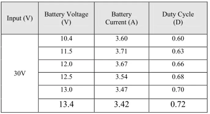
Simulated results have been carried out with two input voltage range. For the output reading, input voltage was fixed at 30V and 20Volt. The observation of first set of readings for input voltage 30V is depicted in Table 1.
Table (1): Battery charging at input voltage of 30V
Input (V) Battery Voltage (V)
Battery Current (A)
Duty Cycle (D)
30V
10.4 3.60 0.60
11.5 3.71 0.63
12.0 3.67 0.66
12.5 3.54 0.68
13.0 3.47 0.70
13.4 3.42 0.72
The second observation has been made with input voltage of 20Vand depicted in Table (2).
Table (2): Battery charging status at input voltage 20V
Input (V) Battery Voltage (V)
Battery Current (A)
Duty Cycle (D)
20V
10.4 3.52 0.75
11.0 3.68 0.80
11.5 3.62 0.82
12.0 3.75 0.85
12.5 3.81 0.88
13.0 3.49 0.91
The curve shown by the blue line in Fig.5 represents the output waveform of the circuit. It can be easily seen that output is in form of pulses .These pulses have been allowed to pass through the battery.
Fig 5. Simulated Waveform of pulse charging (X =7.2 V/div, Y = 10 ms /div)
switching device. When the switch was in “OFF” state, the current flowing through the battery was “zero”. As the switch became “ON” a pulse was generated as output. Again, as the switch was turned “OFF”, the pulse vanished. So the pulse width was made dependent upon the “ON” and “OFF” time of the MOSFET switching device.
The current through the battery is supposed to be constant about 3.6A but in simulated result, it was found that current varied from 3.4A to 3.8A. So, the error in current has been observed as ± 6% which was quite small.
7. CONCLUSION AND FUTURE WORK
In the proposed project work a mobile battery charger has been investigated with a PWM charging unit for automobile industry. The hardware realisation as external unit may bring a new technology to utilise renewable sources and can replace petrol /diesel driven automobile completely. Further integration of the system directly with the converter unit driving the wheel not only will save the cost but reduce the extra weight added to automobile and thus will be able to increase the efficiency.
REFERENCES
[1]Ali M. Eltamaly, “modeling of wind turbine driving permanent magnet generator with maximum power point tracking system”, Elminia, Egypt.
[2] S. Arul Daniel and N. Ammasai Gounden,” A stand alone integrated array wind turbine gen and photovoltaic-array in feed-forward controlled PWM inverter”, India, December 2001.