IJER@2015
Page 118
The Numerical Analysis of Flow Field on Warship Deck
Kwan Ouyang
a, Reui-Kuo Lin
a,*, Sheng-Ju Wu
b, Wen-Hann Sheu
ca
Department of Marine Engineering, Taipei College of Maritime Technology, No. 212, Sec. 9, Yen Ping N.
Rd.,Shihlin Dist., Taipei 11174, Taiwan (R.O.C.)
b
Department of Power Vehicle and Systems Engineering, Chung Cheng Institute of Technology, National
Defense University, No. 75, Shiyuan Rd., Dashi Jen 335, Taoyuan, Taiwan (R.O.C.)
c
Department of Engineering Science and Ocean Engineering, National Taiwan University, No. 1, Sec. 4,
Roosevelt Road, Taipei 10617, Taiwan (R.O.C.)
* E-Mail: rklin@mail.tcmt.edu.tw
Abstract:This study aims to simulate the exhaust flow field of ship by the method of computational fluid dynamics (CFD) concerning with the interference by exhaust temperature, shape of stack and rolling angles etc.. In this research wind tunnel test for a corvette has been performed to attain associated experimental data, which were used as a reference basis. During simulation process several configurations of stacks have been selected, and combining with various rolling angles, exhaust temperatures and velocities, we have gene-rated numerous cases from which the diffusion paths and temperature distribution of the exhaust flow field can be clearly observed and analyzed. In terms of numerical simulation, the packaged program computational fluid dynamics software has been adopted. The simulation results also possess the same trend as the experimental data, which have initially confirmed the methods developed here can be used for the arrangement of stack and superstructure at the stage of initial and conceptual design of ships.
Keywords—computational fluid dynamics, diffusion distribution, wind tunnel test, smoke diffusion, atmospheric pressure.
I. I n t r o d u c t i o n
Submarine is the best vehicle to attack surface ships only is the biggest threat to maritime lifeline, submarines must constantly change shape. When the submarine submarines traveling directly affect the shape of the bear resistance, especially in the shape of a steep submarine submarines its greater resistance line. The streamlined shape of submarines (streamlining) submarine-shaped resistance can be reduced, however, the factors to be considered in the design also includes the cost of loading capacity, regulations and aesthetics. Submarine design is hoping to carry more weapons and a number of people, so its shape more to the main square, and then through the local modification (rounded edge guide, increase diversion devices, etc.) in order to reduce drag. How effective is this modified, must through analysis of its submarines and thus outside the flow and pressure it to calculate the resistance caused by the distribution of submarine surface [1, 2].
The streamlined shape of submarines (streamlining) can reduce boat drag, but also need to be considered design factors including price, loading, regulations and aesthetics. Such as freight wheel design is hoping to be loaded once more and the number of goods, so its shape to the main square, and then through the local modification (rounded edge guide, increase
diversion devices, etc.) in order to reduce drag. The effect of this revised how must thus calculate the airflow through the analysis of its submarines outside its on submarines and surface resistance caused by pressure distribution [3, 4]. This ability to build a first-class field analysis is an urgent demand for domestic shipyards. With the rapid advances in computer technology under the new ship launch and shorten the time trend, the use of computational fluid dynamics techniques [5, 6] for solving the three-dimensional shape of the ship incompressible viscous flow field and pressure field in order to establish useful library of hydrodynamic and pressure distribution of the modern methods used in shipyard design department [7].
Value on water dive Motion flow field of calculation methods, in the past, mainly in potential theory (potential theory) and Reynolds-averaged Navier-Stokes equations governing the calculation equations. Potential theory that the central idea of the basic assumptions of the ideal fluid flow (ideal flow) and then solving the Laplace equation [8], the solution process and the establishment of the Green's function integral equation of potential flow, this method requires the use of a computer for the effectiveness of the more relaxed, so far still widely academic use, MC Fang in 2007 this method to solve the catamaran to change the unsteady flow field of sports, the results and found steady trend in the flow field of high-speed and long-wave longitudinal catamaran shake (yaw) and yaw (pitch) has a considerable impact [9]; the same year, Zhu Renchuan, who also uses the potential theoretical simulation of fixed offshore oil platforms and coastal ship when docked in numerical wave flume whole flow field analysis, to be solved with the finite volume method [10]; CP Chen in 2005 places the potential theory with Dawsonz methods and a small plate method catamaran Hing predicted wave resistance of [11], but because of a potential theory ignored fluid viscosity of the calculation, simulation of fluid motion can be regarded as an idealized
mathematical model, can’t make a better interpretation of the
IJER@2015
Page 119
flow is the main factor affecting the submarine hydrodynamic flow field and the field of [13].
Computational fluid dynamics calculations applied to the hull or underwater vehicle body such as numerical simulation of flow field vehicles, generally can be divided into two kinds of relative motion with dynamic mesh model; in relative motion flow field numerical model, meaning that grid position fixing member, leaving the surrounding fluid motion for the case of modal flow field analysis, 1996 Y. Tahara, who applied the model to solve the boundary ship, tail torrent field and wave flow field, experimental places RANS equations with the Baldwin-Lomax turbulence model for solving [14]; 2001 CMP Sampaio and others to calculate the relative motion model semi-displacement boat ilk field of fundamental physical quantity, then that is not the same displacement as well as the wedge angle on the ship stern body flow field change on very huge [15]; Chang Yu in 2006 in unsteady viscous to RANS equation solver with the VOF model submarine formation ilk field in multiphase flow, the experimental dynamic grid calculation domain is divided, waves and surface waves given symmetry (symmetrically) boundary conditions at several different Buddha labor internally generated and subsequently found to increase the number of its internal labor Buddha wavelength also increases [16]; the same computing underwater voyage ultra cavitation body in motion after the high-speed launch in 2007 YL Xiong numerical method and prove such a propulsion unit will be able to improve navigation speed at low thrust state [17]; 2002 Ivan Malcevic use of dynamic grid computing Lagrangian point in the flow, the micro-structure of the blood in which fluid flow field desorption [18].
In this study, the use of numerical simulation software package, will be done with the results of the analysis of the flow field measurement results compare to verify the correctness of the value of the platform. In this paper, through research, is expected to be reached in incompressible flow and mass conservation conditions to analyze the flow field containing a submerged body skeg for the sail and move them to build "the body of the value of the water tank dive" feature.
II. Governing equations
Hydrodynamic flow field before carrying value of the analysis, we do a few basic assumptions: (1) fluid is a non-Newtonian fluid and has a compression (incompressible flow); (2) three-dimensional transient flow field flow (transient ); (3) to ignore the impact of energy and gravity.
In order to investigate the hydrodynamic flow field outside of submarines, will this paper methods of computational fluid dynamics, which means using the finite volume method and follow the law of conservation (conservation law) principles for the integration of a variety of types that direct discrete physical domain its advantages can choose any shape of the grid, considering a transfer equation (1) below the form
S V
t
) ( )
( (1)
where
the density of water, t the time, V the velocity vector, the dependent variable, the diffusion coefficient and the source term. Flow field analysis is focused on the solution of three-dimensional transient Navier-Stokes equations, which mustsatisfy the continuity equation and the momentum equations incompressibility condition of the form are as follows
0 ) ( V t
(2) )] ) ( ( [ * )( V V P eff V V T
t
V
(3) which eff viscosity coefficient ( eff LT ) can be
decomposed into laminar viscosity coefficient L, the turbulent viscosity coefficient Tfor the static pressure P*is defined as follows k P P 3 2
* (4)
For turbulent flow to turbulent eddy viscosity hypothesis defined viscosity coefficient T. The basic k-ε turbulence model
T C k2 (5)
where C is a constant, k is the turbulent kinetic energy, ε is the rate of turbulent dissipation. Item selection criteria to solve the pressure mode, the pressure and velocity coupling term SIMPLE algorithm is then chosen, and the choice of second-order line item convection upwind difference method, the turbulent flow field pattern on the experiment results show that the use of basic than the k- ε model can be more accurate. For k and ε, we can separately from the turbulent kinetic energy dissipation rate equation and turbulent kinetic energy equation to obtain.
Turbulent kinetic energy equation:
k k T
L k P
k V t k ] ) [( ) ( ) ( (6) Turbulent kinetic energy dissipation rate equation:
) ( ] ) [( ) ( ) ( 2 1 C P C k V t k T
L
(7 )
where (3 )
3 2 )
( V V V V k
V
P T
T T
k . Within the three-dimensional context, the time-dependent, incompressible Navier-Stokes equations are solved together with the divergence-free constraint equation using the unstructured finite-volume code. In co-located grids, the Rhie-Chow interpolation [19] is employed to avoid the oscillatory pressure due to even-odd decoupling. For the sake of reducing the numerical diffusion error, the second order upwind scheme is used to approximate the convection terms, while the diffusion terms are discretized by the second-order accurate centered scheme. In the present method, a fully implicit backward time-stepping scheme for the approximation of temporal derivative terms is adopted at the time increment t=0.005s so as to be able to predict the true flow physics. To accelerate the convergence, the resulting discretized equations are solved within the algebraic multigrid context. Finally, some significant physical insights will be visualized by virtue of the employed post-processor tool.
IJER@2015
Page 120
Verification of DARPA SUBOFF
First, in order to prove the availability and accuracy of the software packages used in this article, we use a symmetrical geometric shape with a DARPA SUBOFF [1] (Figure 1), geometry length of 4.356m, the boundary conditions: fluid inflow velocity to 1.0m/sec, the outlet for the static pressure is zero; assuming fluid is water (density 997.0 kg/m3, dynamic viscosity of 8.899x10⁻⁴ kg/ms), the Reynolds number Re is 1.2x10⁶ (in Table 1). Tetrahedron grid system for patterns in CFD software automatically generates the unstructured computational grid, with a total of 301,971 grid points a. Distribution grid as shown, the outer surface of which at DARPA SUBOFF, adopt a more dense grid, in order to facilitate the analysis of boundary layer flow field. The figure below shows the experimental values of the literature [1], numerical calculations [2] The results of the comparative analysis.
(a)
(b)
Figure 1: DARPA SUBOFF geometry (a) geometry; (b) surface mesh
angle of
attack 0
o
8o 16o 30o
length (m) 4.356 4.356 4.356 4.356
inlet
velocity 1.0 1.0 1.0 1.0
Reynolds
number 1.2×10
6
1.2×10⁶ 1.2×10⁶ 1.2×10⁶
Table 1: DARPA SUBOFF geometry and boundary conditions
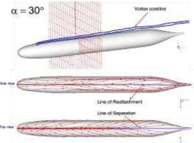
Figure 2 shows the DARPA SUBOFF 0 degrees angle of attack pressure Cp value distribution, Figure 3 shows the numerical difference in the angle of attack for the comparison of 0 degrees, 8 degrees and 16 degrees when the pressure Cp value distribution with the literature [2], Figure 4 for DARPA SUBOFF respectively, attack angle is 0 degrees, the limit of the distribution of surface flow lines 8 degrees and 16 degrees. Figure 5 shows the angle of attack respectively 0,8,16 and 30 degrees to the velocity vector x=2,3 and 4 on the surface of the cross section, Figure 6 shows the DARPA SUBOFF attack angle of 30 degrees with the surface of the vortex line limits the flow line.
NACA wing flow field verification
Then NACA0012, 0018 and 0020 respectively monoplane placed in numerical hydrodynamic analysis, the geometry shown in Figure 7, the wing length of 1.0m, the inflow velocity of 1.0m/sec., And the computational domain length 10.0 m, Reynolds is 7.3653x10⁶, grid point number is 188,700, (tetrahedral grids to 773,898, wedges of 86,150). With
NACA0012, for example, Figure 8 shows the calculation of the surface of the grid NACA 0012 (y =xz plane and 0.5), Figure 9 for the NACA0012, 0018 and 0020 wing pressure varies with the position of the Cp value distribution. Figure 10(a) shows the NACA0020 Flowing sectional profile, Figure 10(b) is a cross-sectional surface of the NACA wing pressure isobars distribution [23].
Figure 2: DARPA SUBOFF 0 degrees angle of attack pressure Cp value distribution
(a)
(b)
(c)
IJER@2015
Page 121
(a)
(b)
Figure 4: Limit the flow line of the distribution of surface, angle of attack (a) 16o; (b) 30o
V. Conclusion
Flow chart shows also generate a recirculation zone at the end of the submarines. Last recirculation zone flow field submarine submarines performance impact caused when traveling on is great, and it is extremely complex physical phenomena, making further understand its mechanism. This calculation can capture complex submarine at the vortex trajectory. This result can be used in the future to improve the appearance of the tail with submarines. Through CFD scientific computing (scientific computing), you can understand the detailed structure of submarines outflow field distribution, which can be used in submarine design process is an important reference database. Fully integrated CAD/CAE analysis tools, has native build submarines numerical wind tunnel prototype platform, through a combination of the future more detail.
(a)
(b) Figure 5: Angle of attack were 0o,8o,16o and 30 o degrees in x=2,3 and 4 on the surface section of the velocity.
Figure 6: DARPA SUBOFF attack angle of 30 degrees to the surface of the vortex line limit flow lines
Figure 7: NACA wing geometry of the schematic
(a) Figure 8: NACA0012 calculate the surface of the grid
IJER@2015
Page 122
Figure 10: NACA 0020 section on the streamline distribution
Acknowledgement
The financial supports from the National Science Council under grant NSC97-2221-E-002-250-MY3, CQSE project 97R0066-69 and Ching-Lin Industrial Center are gratefully acknowledged.
References
i. Cox B. D. and Reed A.M. (1998) Contrarotating propellers-design theory and application, The Popellers’ 88 Symposium, Virginia, No. 15
ii. Hadler, J. B., W. B. Morgan, and K. A. Meyers. (1964) Advanced propeller propulsion for high-powered single-screw ships. Trans SNAME, 72:231-93
iii. Dashnaw. F. J., A. W. Forrest, J. B. Hadler, and G. C. Swenssen. (1980) Application study of contrarotating propulsion for a US Flag merchant ship. Philadelphia Section SNAME Paper (5 Dec.), 71
iv. Strack, W. C., G. Knip, A. L. Weisbrich, J. Godston, and E. Bradley. (1982) Technology and benefits of aircraft counter rotation propellers. NASA-TM-82983, 35
v. Kumar Srinivasan, James Y. Jan, Richard L. Sun and Mark E. Galeason (2000), 'Rapid simulation methodology for under-hood aero/thermal management', Int. J. of Vehicle Design, Vol. 23(1/2): 109-123
vi. Tatsuya Shimizu, Yuji Hanaoka (2000), 'Practical
Aerodynamic Simulation Method Using Unstructured Grid System', J. of Society of Automotive Eng. Of Japan, Vol. 54(4): 65-69
vii. Fang, M. C. and Hsu, Y. S., (2007) The combined effect of the steady potential on the unsteady motions of twin-hull ship in waves, Journal of Taiwan Society of Naval Architects and Marine Engineers, Vol. 26, No, 4, pp. 203-211
viii. Zhu, R. and Lin, Z., (2006) Numerical simulation for green water occurrence, Conference of Global Chinese Scholars on Hydrodynamics, pp. 498-504
ix. Chen, J. P. amd Zhu, D. X., (2006) Research on numerical method for wavemaking resistance of catamaran trimaran, Journal of Ship Mechanics, Vol. 10, No. 2, pp. 23-29
x. Hong, F. W. and Chang, Y., (2005) Numerical simulation of surface wake for submarine moving in homogeneous fluid, Journal of Ship Mechanics, Vol. 9, No. 4, pp. 9-17
xi. Zhang, N. and Shen, H. C., (2007) Numerical simulation of jet flow around submarine, Journal of Ship Mechanics, Vol. 11, No. 1, pp. 10-21
xii. Tahara, Y. and Stern, F., (1996) A large-domain approach for calculating ship boundary layers and wakes and wave fields for nonzero froude number. Journal of Computational Physics, No. 183, pp. 398-411
xiii. Sampaio, C. M. P. and Nishimoto, K., (2001) Numerical and experimental evaluation the hull characteristics of two-semi-displacement fast monohulls. Elsevier B.V.
xiv. Chang, Y. and Hong, F. W., (2006) Numerical simulation of internal waves excited by a submarine moving the two-layer stratified fluid. Conference of Global Chinese Scholars on Hydrodynamics, pp. 330-336
xv. Xiong, Y. L. and Gao, Y., (2007) Numerical study of drag reduction ability on supercavitation vehicle, Journal of Ballistics, Vol. 19, No. 1, pp. 41-54
xvi. Malcevic, I. and Ghattas, O., (2002) Dynamic-Mesh Finite Element Method for Lagrangian Computational Fluid Dynamics, Finite Elements in Analysis and Design, pp. 965-982
xvii. Patankar, S. V., (1980) Numerical Heat Transfer And Fluid Flow, Hemisphere, Washington. DC
xviii. W. Shyy (1994), Computational modeling for fluid flow and intcrfacial transport, Amsterdam: Elsevier, 143-145
xix. Taeyoung Han (1989), 'Three-dimensional Navier-Stokes Simulation for passenger compartment cooling', Int. J. of Vehicle Design, Vol. 10(2): 175-186.
xx. G. D.Raithby (1991) Equations of motion for reacting, particle-laden flow, progress report, Thermal science Ltd., Provided to EMR
xxi. Groves N C; Huang, T T; Chang, M S (1989), Geometric Characteristics of DARPA SUBOFF Models. David Taylor Research Center, DTRC/SHD-1298-01