DECLARAÇÃO
Nome: Sara Tribuzi de Melo Nunes de Morais
Endereço eletrónico: [email protected] Telefone: +351 927 668 087 Número do Bilhete de Identidade: 13350994
Título dissertação:
Development of a Biomechanical Spine Model for Dynamic Analysis Ano de conclusão: 2011
Orientador:
Professor Doutor João Paulo Flores Fernandes Designação do Mestrado:
Ciclo de Estudos Integrados Conducentes ao Grau de Mestre em Engenharia Biomédica Área de Especialização: Biomateriais, Reabilitação e Biomecânica
Escola: de Engenharia
Departamento: de Engenharia Mecânica
DE ACORDO COM A LEGISLAÇÃO EM VIGOR, NÃO É PERMITIDA A REPRODUÇÃO DE QUALQUER PARTE DESTA TESE/TRABALHO.
Guimarães, ____/____/________
iii
Acknowledgments
To my supervisor, João Paulo Flores Fernandes, for the guidance throughout this last project of my Integrated Master degree.
To the project NP Mimetic - Biomimetic Nano-Fiber Based Nucleus Pulposus Regeneration for the Treatment of Degenerative Disc Disease, funded by the European Commission under FP7 (grant NMP3-SL-2010-246351), for providing my MSc student grant.
To my co-workers at Centre for Mechanical and Materials Technologies (CT2M), University of Minho, for the excellent work environment and team spirit provided, and especially to Margarida Machado, for always having a helpful advice for my doubts.
To my friends who, no matter how near or far, encouraged me to pursuit this goal.
And last and most importantly, to my family for supporting me in every way through these last five years of education and personal development.
v
Abstract
Development of a Biomechanical Spine Model for Dynamic Analysis
The vertebral column is a complex structure that has a variety of functions in human body stability. This stability can be affected by a myriad of pathologies, from which the degenerative disc diseases group is one of the most relevant, since it is related to low back pain, a symptom that affects the majority of the population at some point of their lives.
This six-month master degree dissertation aims at developing an useful computational tool for the dynamic analysis of the lumbar spine in response to traumatic and degenerative events.
To accomplish this goal, a two-dimensional lumbar spine model (from vertebra L1 to S1) was developed, composed by a set of rigid bodies, constrained by nonlinear viscoelastic elements as ligaments, linear viscoelastic bushing elements as intervertebral discs and contacts between facet joints and spinous processes, following the hertzian contact theory augmented with a dissipative term.
The developed methodologies were individually analyzed in order to validate their implementation in the context of multibody dynamics.
The application of the produced model to different test scenarios was considered, namely the test of the physiologic limits of the relative motion of the vertebrae, the influence of the existence of pathologies and the effect of the application of an external load.
The computational methodologies developed in this work unfold under the objectives of the European Commission’s Seventh Framework Programme project NPmimetic (Project ID: 246351), in the research area NMP-2009-2.3-1 - Biomimetic gels and polymers for tissue repair.
vii
Resumo
Desenvolvimento de um Modelo Biomecânico da Coluna para Análise Dinâmica
A coluna vertebral é uma estrutura complexa que possui diversas funções no que respeita à estabilidade do corpo humano. Esta estabilidade pode ser afetada por uma miríade de patologias, das quais o grupo das doenças degenerativas do disco intervertebral é um dos relevantes, uma vez que está relacionado com a dor lombar, um sintoma que afeta a grande maioria da população numa determinada fase da sua vida.
Esta dissertação de mestrado desenvolvida em seis meses tem como objetivo desenvolver uma ferramenta computacional útil para a análise dinâmica da coluna lombar em resposta a eventos de ordem traumática e degenerativa.
De modo a alcançar este objetivo, foi desenvolvido um modelo bidimensional da coluna lumbosacral (da vértebra L1 até à S1) constituído por corpos rígidos, constrangidos por elementos viscoelásticos não-lineares como ligamentos, juntas viscoelásticas lineares como discos intervertebrais e contactos entre facetas articulares e apófises espinhosas, seguindo a teoria de contacto de Hertz acrescida de um termo dissipativo.
As metodologias desenvolvidas foram analisadas individualmente de modo a validar a sua implementação no contexto da dinâmica de sistemas multicorpo.
Foi considerada a aplicação do modelo produzido a diferentes cenários, tais como o teste dos limites fisiológicos do movimento relativo das vértebras, a influência da existência de patologia e o efeito da aplicação de uma carga externa.
As metodologias computacionais desenvolvidas neste trabalho vão de encontro aos objetivos do projeto NPmimetic (ID do projeto: 246351) do Seventh Framework Programme (FP7) da Comissão Europeia, na área de investigação NMP-2009-2.3-1 - Géis e polímeros biomiméticos para reconstrução de tecidos.
ix
Contents
Acknowledgments ... iii Abstract... v Resumo ... vii Contents... ixList of Abbreviations and Acronyms... xi
List of Figures ...xiii
List of Tables ... xvii
Chapter 1 Introduction ... 1
1.1. Motivation and Scope... 1
1.2. Literature Review ... 2
1.3. Objectives of this Work ... 11
1.4. Structure of the Thesis ... 11
1.5. Contribution of this Work ... 12
Chapter 2 Characterization of the Spine ... 13
2.1. Anatomy ... 13
2.1.1. The Vertebrae ... 16
2.1.2. The Intervertebral Disc... 17
2.1.3. The Lumbar Ligaments ... 18
2.2. Spinal Disorders ... 21
2.3. Solutions for Degenerative Disc Disease ... 26
2.4. Summary and Discussion... 28
Chapter 3 Multibody Systems Formulation ... 29
3.1. Multibody System Concept ... 29
3.2. Cartesian Coordinates... 30
3.3. Equations of Motion for Constrained Systems ... 32
3.4. Solution of the Equations of Motion ... 33
3.4.1. Simulation Software... 35
3.5. Summary and Discussion... 36
Chapter 4 Biomechanical Multibody Spine Model... 37
4.1. Description of the Model ... 37
x
4.1.2. The Intervertebral Discs ... 39
4.1.3. The Ligaments ... 41
4.2. Kinematics of the Contact ... 47
4.2.1. Articular Facets ... 51
4.2.2. Spinous Process... 52
4.3. Contact Force Model ... 52
4.4. Summary and Discussion... 54
Chapter 5 Results and Discussion... 55
5.1. Validation of the Developed Methodologies ... 55
5.1.1. Ligaments... 55
5.1.2. Bushing Elements ... 57
5.1.3. Contact ... 62
5.2. Application to a Functional Spinal Unit... 66
Chapter 6 Conclusions and Future Work ... 69
6.1. Conclusions ... 69
6.2. Future Work ... 70
References... 71
xi
List of Abbreviations and Acronyms
2D Two-dimensional
3D Three-dimensional
AF Annulus Fibrosus
ALL Anterior Longitudinal Ligament
BE Bushing Elements
CL Capsular Ligament
CT Computer Tomography
DDD Degenerative Disc Disease
DIM Direct Integration Method
DOF Degree-of-freedom
EP Endplate
EPI Endplate Inclination
F Flores et al. contact force model
FE Finite Elements
FSU Functional Spinal Unit
IDET Intradiscal Electrothermal Therapy
ISL Interspinous Ligament
IVD Intervertebral Disc
HIC Head Injury Criteria
LBP Low Back Pain
L & N Lankarani and Nikravesh contact force model
LF Ligamentum Flavum
MBS Multibody System
NP Nucleus Pulposus
PLL Posterior Longitudinal Ligament
SSL Supraspinous Ligament
xiii
List of Figures
Figure 1.1 – Lateral view of de Jager’s model: base of the skull and vertebrae, showing the body local coordinate systems {Adapted from (de Jager, 2000)}... 4 Figure 1.2 – Spine/neck and head model developed for analysis of spinal loading {Adapted from
(Waters et al., 2003)}... 5 Figure 1.3 – Esat multibody model of the lumbar spine {Adapted from (Esat, 2006)}. ... 5 Figure 1.4 – Configuration of the model during the lateral impact simulation (from t=0 s to t=0.18
s). The upper row represents the sagittal view and the lower row a frontal view {Adapted from (Ferreira, 2008)}... 6 Figure 1.5 - Multibody model of the lumbar spine developed in Simulink™, under a loading
situation {Adapted from (Fairman et al., 2009)}. ... 7 Figure 1.6 – MBS model of the lumbar spine (L2 - sacrum) obtained by Juchem {Adapted from
(Bauer and Gruber, 2009)}... 8 Figure 1.7 – Hybrid model developed by Monteiro: (a) co-simulation model; and (b) fixation plate
model with titanium fixation screws {Adapted from (Monteiro, 2009)}. ... 9 Figure 1.8 – Detailed musculoskeletal model of the lumbar spine developed by Christophy,
comprising 238 muscle fascicles, 13 rigid bodies, and 5 intervertebral joints: (a) neutral posture and (b) 50° flexion {Adapted from (Christophy, 2010)}. ... 10 Figure 1.9 – Lumbar spine model (L1-sacrum) obtained with MSC.ADAMS® software {Adapted
from (Abouhossein et al., 2011)}. ... 11 Figure 2.1 - Views of the vertebral column, showing the different regions: (a) frontal view; (b) lateral
view {Adapted from (Gray, 1918)}. ... 14 Figure 2.2 – Mobility of the vertebral column: the extent of mobility from zero position (0°) is given
in degrees {Adapted from (Faller et al., 2004)}... 15 Figure 2.3 – Parts of a typical lumbar vertebra: (a) top view; (b) lateral view {Adapted from
(Bogduk, 2005)}... 16 Figure 2.4 – The sacrum: (a) frontal, (b) sagittal and (c) transverse view. Anterior sacral foramina
(asf), remnants of the intervertebral disc (ivd), lamina (la), lateral mass (lm), superior articular process (sap), sacral canal (sc), sacral hiatus (sh), spinous process of S1 (sp) and vertebral bodies (vb) {Adapted from (Bogduk, 2005)}. ... 17 Figure 2.5 - The intervertebral disc: (a) sagittal section and (b) transverse section {Adapted from
xiv
Figure 2.6 – Hierarchical organization of the ligaments: names and diameters of the subelements {Adapted from (Herman, 2007)}. ... 19 Figure 2.7 – Ligaments in the lumbar spine: division in intra- and intersegmental... 19 Figure 2.8 - Medial sagittal section of two lumbar vertebrae and their ligaments {Adapted from
(Gray, 1918)}. ... 20 Figure 2.9 – Spinal disorders: a division in specific and nonspecific disorders. ... 21 Figure 2.10 – Macroscopic disc changes due to DDD, according to Thompson’s classification: (a)
grade I; (b) grade II; (c) grade III; (d) grade IV; (e) grade V {Adapted from (Boos and Aebi, 2008)}. ... 22 Figure 2.11 – Load sharing and intervertebral disc degeneration: (a) normal disc; (b) degenerated
disc {Adapted from (Pollintine et al., 2004)}... 24 Figure 2.12 – The three column spine: (a) anterior, (b) middle, and (c) posterior column {Adapted
from (Denis, 1983)}... 24 Figure 2.13 – Major spinal injury types {Adapted from (Denis, 1983)}. ... 25 Figure 2.14 – Operative techniques for the treatment of lumbar DDD. ... 26 Figure 2.15 – Lumbar disc replacement prosthesis: (a) Baguera ® L, from Spine Art; (b) LP-ESP
®, from FH Orthopedics; (c) Prodisc-L ®, from Synthes; (d) activ® L, from B|Braun. ... 28 Figure 3.1 – Generic representation of a multibody system. ... 29 Figure 3.2 – Multibody systems and the possible analyses of biomechanical systems. ... 30 Figure 3.3 – Locating point P relative to the body-fixed and global coordinate systems {Adapted
from (Nikravesh, 1988)}... 31 Figure 3.4 – Flowchart of computational procedure for dynamic analysis of multibody systems –
Direct Integration Method {Adapted from (Flores and Seabra, 2010)... 34 Figure 4.1 - Posterior vertebral body height (VBHp), and upper (EPDu) and lower (EPDl) endplate
depth in a vertebra. ... 38 Figure 4.2 – Upper ( ) and lower ( ) endplate inclination for a vertebral body considered in the
model... 38 Figure 4.3 - Geometric definition of the bushing element and representation of the initial
translational offset. ... 40 Figure 4.4 – Mechanical behavior of the ligament: load-strain curve Adapted from (Wismans,
xv Figure 4.5 – Ligament hysteresis: loading and unloading. The shaded area represents the energy
loss due to the hysteretic behavior (Yahia et al., 1991). ... 43
Figure 4.6 – Location of the supraspinous (SSL) ligament... 47
Figure 4.7 – Schematic representation of the contact between a sphere and a plane. ... 48
Figure 4.8 – Schematic representation of the relative contact velocity... 50
Figure 5.1 – Schematic representation of a ligament... 55
Figure 5.2 – Ligament behavior: (a) ligament length versus time; (b) ligament velocity versus time; (c) strain versus time; (d) strain rate versus time; (e) elastic force versus strain; (f) total force versus strain... 56
Figure 5.3 – Schematic representation of a bushing element actuating on the y-direction... 57
Figure 5.4 – Behavior of the bushing element (y-direction, =0 m/s): (a) bushing length; (b) bushing velocity; (c) elastic force; (d) damping force; (e) total vertical force. ... 58
Figure 5.5 - Behavior of the bushing element (y-direction, =10 m/s): (a) bushing length; (b) bushing velocity; (c) elastic force; (d) damping force; (e) total vertical force. ... 59
Figure 5.6 – Schematic representation of a bushing element acting on the x-direction. ... 60
Figure 5.7 - Behavior of the bushing element (x-direction, =0 m/s): (a) bushing length; (b) bushing velocity; (c) elastic force; (d) damping force; (e) total horizontal force. ... 61
Figure 5.8 – Behavior of the bushing element (ϕ-direction): (a) orientation of body i; (b) angular variation; (c) relative angular velocity; (d) elastic moment; (e) damping moment; (f) total bushing moment. ... 61
Figure 5.9 – Bouncing ball example. ... 63
Figure 5.10 – Kinematic simulation results of a ball falling on the ground: (a) ball position; (b) ball velocity. ... 63
Figure 5.11 – Influence of the contact model on the bouncing ball behavior ( =0.9): (a) deformation; (b) velocity of deformation; (c) contact force; (d) contact force-deformation relation. ... 64
Figure 5.12 – Influence of the contact model on the bouncing ball behavior ( =0.616): (a) deformation versus time; (b) velocity of deformation versus time; (c) contact force versus time; (d) contact force-deformation relation. ... 65
Figure 5.13 – Multibody model of two consecutive vertebrae and their fundamental elements (bodies, ligaments, bushing elements and potential contact areas) {Adapted from (Tribuzi et al., 2012)}. ... 66
xvi
xvii
List of Tables
Table 1.1 - Landmarks in the history of spinal biomechanics {Adapted from (Sanan and Rengachary, 1996)}... 2 Table 2.1 – Spinal regions and vertebrae numbering and main functions. ... 13 Table 2.2 – Limits and representative values of ranges of rotation of the lumbar spine {Adapted
from (White and Panjabi, 1990)}... 15 Table 2.3 – Lumbar ligaments: acronyms, anatomical areas connected and functions. ... 20 Table 4.1 – Initial coordinates of the center of mass, local frame orientation, mass and moment of
inertia of the rigid bodies considered in the presented model {Adapted from (Monteiro, 2009)}... 37 Table 4.2 – Posterior vertebral body height (VBHp), and upper (EPDu) and lower (EPDl) endplate
depth of each considered vertebral body {Adapted from (Panjabi et al., 1992)}... 38 Table 4.3 – Upper ( ) and lower ( ) endplate inclination for each vertebral body considered in
the model (Adapted from (Panjabi et al., 1992)). ... 39 Table 4.4 – Local coordinates of the points defining the bushing element (BE) and initial
translational and angular offset between those points: S - slave body; M - master body {Adapted from (Monteiro, 2009)}. ... 39 Table 4.5 - Material properties of the bushing elements (BE) for several load directions {Adapted
from (Monteiro, 2009)}. ... 41 Table 4.6 – Properties of the lumbar ligaments: stiffness coefficient, and transition and maximum
strains {Adapted from (Pintar et al., 1992)}... 44 Table 4.7 – Local coordinates used in the definition of the capsular ligaments (CL) in the lumbar
spine {Adapted from (Monteiro, 2009)}. ... 44 Table 4.8 – Local coordinates used in the definition of the interspinous ligaments (ISL) in the
lumbar spine {Adapted from (Monteiro, 2009)}. ... 44 Table 4.9 – Local coordinates used in the definition of the ligamentum flavum (LF) in the lumbar
spine {Adapted from (Monteiro, 2009)}. ... 45 Table 4.10 – Local coordinates used in the definition of the anterior longitudinal ligaments (ALL) in
the lumbar spine {Adapted from (Monteiro, 2009)}... 45 Table 4.11 – Local coordinates used in the definition of the posterior longitudinal ligaments (PLL)
xviii
Table 4.12 – Local coordinates used in the definition of the supraspinous ligaments (SSL) in the lumbar spine {Adapted from (Monteiro, 2009)}. ... 46 Table 4.13 – Geometrical properties of the sphere-plane contacts: plane and sphere reference
point and its corresponding limits for the articular facets {Adapted from (Monteiro, 2009)}... 51 Table 4.14 – Geometrical properties of the sphere-plane contacts: plane and sphere reference
points and its corresponding limits for the spinous process contacts {Adapted from (Monteiro, 2009)}. ... 52
Chapter 1
Introduction
“Low back pain, the most common spinal disorder, affects over 80% of persons at some point in their life, and from 4 to33% of a population at any one time.”
in World Health Organization, 2011
1.1. Motivation and Scope
The World Health Organization reports chronic diseases as the most common cause of mortality, with 63% of deaths worldwide. In 2008, 36 million people died from pathologies of this group, such as heart disease, stroke, cancer, chronic respiratory diseases or diabetes, among other, and from those, 9 million of the victims were younger than 60 years and 90% of those deaths occurred in low and middle-income countries (WorldHealthOrganization, 2011).
Such a broad group of pathologies embraces several types of disorders. For instance, the chronic rheumatic conditions is a subgroup of chronic diseases that comprises more than 150 diseases and syndromes that affect the musculoskeletal system and are generally progressive and associated with pain. The Portuguese Health Ministry reports rheumatic diseases as the most frequent group of illnesses in developed countries, having a vast socio-economic impact, since they originate functional disability and incapacity for work (MinistériodaSaúde, 2011).
From the chronic rheumatic conditions group, the pathologies with greatest impact on society are rheumatoid arthritis, osteoarthritis, osteoporosis and spinal disorders. This set of diseases can be even more narrowed as spinal disorders are a common source of incapacity, especially when related to rachialgia, or pain in the vertebral column. The most common type of rachialgia is low back pain (LBP), and this is a symptom rather than a disorder, since approximately 80% of the cases have no known cause.
Approximately 80% of the population has LBP at some point of their life and 5% has it continuously. The high incidence of this symptom does not mean it is fully understood, as 80-85% of the LBP occurrences do not have a known cause. Thereby, this is the most common cause of disability among people younger than 45 years.
From the known causes of LBP, the lumbar disc disease has been identified as the most common cause (Kraemer, 2008). This evidence is the motivation for this work, whose purpose is to develop a multibody lumbar spine model useful for simulation of this spinal region in several conditions such as the test of the physiologic limits.
1.2. Literature Review
Spinal biomechanics is a branch of Biomechanics, which is broadly described as the application of mechanical principles to biological systems, and has its roots back in the ancient Egypt. The first proof ever found about the study of the mechanics of the vertebral column dates back to 2000 BC and reports about spinal injury. A brief description of the most important publications in spinal biomechanics history is organized in Table 1.1.
Table 1.1 - Landmarks in the history of spinal biomechanics {Adapted from (Sanan and Rengachary, 1996)}.
Year Author Document Significance
2600-2200 BC Imhotep ? Edwin Smith surgical papyrus First record of spinal injury 3500-1800 BC Unknown Srimad Bhagwat Mahapuranam First record of treatment for spinal deformity
460-361 BC Hippocrates Corpus Hippocraticum Spinal manipulation practiced
1452-1519 da Vinci De Figura Humana First attempt to describe spinal stability
1543 Vesalius De Humani Corporis Fabrica Spinal anatomy accurately described
1646 Hildanus Opera quae Extant Omnia Routinely reduced cervical dislocations
1675 Descartes Tractus de Homine et de Fomatione Foetus Proposed mechanistic theory of the human body
1680 Borelli De Motu Animalium The “Father of Spinal Biomechanics”
1736 Euler De Curvas Elasticus Described mathematical stability of a column
1892 Wolff Das Gesetz der Transformation der Knochen Noted that trabeculae align along stress lines
1905 Burrell Fracture of the spine Seminal observations on spinal cord injury
1913 Wood-Jones The ideal lesion produced by judicial hanging Described the “hangman’s fracture” 1970 Holdsworth fracture-dislocations of the spine Fracture, dislocations, and Two-column model of spinal stability
1983 Denis
The three column spine and its significance in the classification of
acute thoracolumbar spinal injuries
Three-column model of spinal stability
Even though he was not the first author to describe spinal biomechanics, Giovanni Borelli is considered the “Father of Spinal Biomechanics”, due to his 1680 book “De Motu Animalium”, in
which concepts such as the viscoelasticity of intervertebral discs are already described (Sanan and Rengachary, 1996).
Since then, the biomechanical study of the human vertebral column has evolved in several fields, from the clinical point of view in the analysis of vertebral geometries to the mechanical importance of spinal elements, such as muscles or the contact between facet joints.
The wide range of publications in this field becomes a large path in the search for information useful for the development of this work. Due to this circumstance, this literature review focuses on the multibody or hybrid spine models available, whether their focus is the cervical, lumbar or whole spine, having in mind its importance for the scope of this work. Apart from this field, a single reference is made to the work performed by Panjabi et al. (1992) in the geometric definition of the spinal components, accentuating the importance of this series of works in the creation of computer models, not only in the present project but also for various authors.
In 1995, Menon developed a two-dimensional model for the human head-neck-torso system using both rigid and rigid-flexible approaches to study the dynamic response and injury mechanisms of this system, by subjecting it to different acceleration/force pulses in order to simulate real crash situations. The multibody model included nine rigid bodies (head, 7 cervical vertebrae and the first thoracic vertebra) connected by revolute joints and resulting in nine degrees--of-freedom (DOF). The effect of muscles, intervertebral discs (IVD), cartilage, ligaments, cerebrospinal fluids and other tissues was included through non-linear rotational springs and dampers. The performed simulation analyzed the head’s resultant linear and angular accelerations, velocity and position for acceleration values of 6 and 15 G applied to the T1 vertebra. The model has proved to be suitable for the correct evaluation of the Head Injury Criterion (HIC) (Menon, 1995).
De Jager (2000) presented a detailed three-dimensional mathematical model describing the dynamic behavior of the human head and neck in accident situation without head contact. His work has developed in three stages: (i) a global head-neck model was built, with rigid head and vertebrae, connected through 3D nonlinear viscoelastic elements that lumped the characteristics of IVD, ligaments and facet joints; (ii) detailed segments of the cervical spine were proposed, with 3D linear viscoelastic elements for the IVD, nonlinear viscoelastic elements for the ligaments, and frictionless contacts in the facet joints; and finally (iii) Hill-type muscles were included in the model
developed in the previous step (de Jager, 2000). Figure 1.1 shows the schematic representation of the global model with local coordinate systems.
After several tests, calibration with human volunteers, introduction of loads, de Jager concluded that the active muscle behavior was essential to describe the system’s response to impact and that his model was computationally efficient, suitable for car safety improvement, and calculation of neck injury criteria, since the loads and deformations of individual tissues are computed through the model.
Figure 1.1 – Lateral view of de Jager’s model: base of the skull and vertebrae, showing the body local coordinate systems {Adapted from (de Jager, 2000)}.
A detailed geometry is not always a synonym of accuracy on the outputs. Waters and co-workers (2003) presented a multibody model for the assessment of the risk of low back disorders due to occupational exposure to jarring and jolting from operation of heavy mobile equipment. The full 17 rigid bodies model of the whole body initially used was replaced by a simpler approach. Figure 1.2 illustrates the 4-body model representing head/neck and upper, middle and lower torso interconnected by a set of springs and dampers that was used to simulate the gross motion of the spine, becoming a more efficient system and not losing accuracy.
Using seat acceleration data from vehicles as input this model allows for the evaluation of the forces generated at the seat, and the force at the L5/S1 joint for the same input. It is also possible to calculate the cumulative adverse health effects factor for a low and high risk jarring and jolting.
Figure 1.2 – Spine/neck and head model developed for analysis of spinal loading {Adapted from (Waters et al., 2003)}.
The work proposed by Esat (2006) represents a hybrid model of the whole spine, comprising a multibody model used for dynamics analysis of impact situations, and a finite element analysis to study the causes of injury in specific spinal components. The reaction forces associated with lumbar motion segments, for instance, are used to analyze the gross kinetics and kinematics of the spine, and also as the boundary conditions for the finite element model of the selected spinal components.
This multibody model used geometric data from computer tomography (CT) imaging, improving the definition of surfaces and therefore providing more realistic data to the contacts. The vertebrae were modeled as rigid bodies, interconnected by linear viscoelastic IVD elements, nonlinear viscoelastic ligaments and contractile muscle elements with passive and active behavior. The influence of the contact forces was not included. The validation of this model was performed by subjecting the model to a 10 Nm flexion moment at the L1 level, and comparing the flexion moment results and intradiscal pressure obtained with other validated models. The model showed good agreement with literature data in both situations.
Ferreira (2008) established a three-dimensional cervical multibody spine model with 9 rigid bodies (head, 7 cervical vertebrae and the first thoracic), connected by six bushing elements with 6 DOF each (for the IVD) and constrained by nonlinear viscoelastic elements simulating the ligaments. Contact events between bony elements (between facet joints and spinous processes) were also included as sphere-plane nonlinear contact forces, following the Kelvin-Voigt formulation.
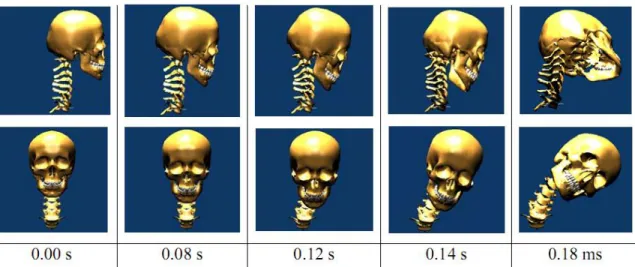
The model was built for simulation of traumatic and degenerative disorders, such as rheumatoid arthritis. Figure 1.4 shows the sagittal (upper row) and frontal view (lower row) of the configuration of the model during an impact simulation. Changing the range of motion and other properties of the elements of the model, according to the effects of the disorder reported in literature, allowed to conclude that the transverse ligament is the most important in maintaining the neck stability, whereas the lateral impact simulation reported element forces and ranges of motion for the different cervical levels.
Figure 1.4 – Configuration of the model during the lateral impact simulation (from t=0 s to t=0.18 s). The upper row represents the sagittal view and the lower row a frontal view {Adapted from (Ferreira, 2008)}.
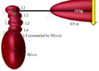
Fairman et al. (2009) developed a multibody model of the lumbar spine with the MATLAB® simulation tool Simulink™. Simple geometric shapes were used to model the vertebrae, and the joints between them were modeled as a network of springs and dampers representing not only IVDs but also ligaments. Virtual muscles were added as actuators of the model. Figure 1.5 depicts the model obtained by Fairman and co-workers under a loading situation.
A forward dynamics analysis was performed and the forces in the lumbar joints could not be calculated through this simulation. The model was tested with the input of a sinusoidal path to encourage smoothness of the motion (amplitude of 20 degrees and frequency of 1.67 Hertz),
considering only the L5-S1 joint as a working joint, and results showed that the maximal compression forces at the pelvis reached 1600 N, and over 1000 N when lifting a 10 kg load.
Figure 1.5 - Multibody model of the lumbar spine developed in Simulink™, under a loading situation {Adapted from (Fairman et al., 2009)}.
The work of Juchem (2009) comprised a three-dimensional computer model of the lumbar spine for the determination of mechanical stresses. Five rigid bodies were modeled (L2 to L5 vertebrae and the sacrum), and their geometries were obtained through computer tomography (CT) measurements. The multibody system (MBS) methodology was applied and the IVDs were modeled as elastic elements between the corresponding vertebral bodies. The effect of the ligaments and the contacts between bony parts (facet joints) were also included. Figure 1.6 represents the lumbar spine model obtained, comprising vertebrae L2 to sacrum.
The model was subjected to an external force of 395 N acting on the top of the L2 vertebra to simulate the upper body’s weight. The performed simulation allowed the calculation of forces and moments in each IVD as well as the forces in the ligaments, confirming the aptitude of the MBS modeling in the estimation of forces and moments in biological structures. It was referred the further applicability of the model in calculating stresses in intact IVDs resulting from the implantation of devices (Bauer and Gruber, 2009; Juchem, 2009; Juchem and Gruber, 2009).
Figure 1.6 – MBS model of the lumbar spine (L2 - sacrum) obtained by Juchem {Adapted from (Bauer and Gruber, 2009)}.
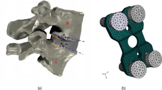
Recently, a hybrid model was created by Monteiro (2009), using multibody system dynamics and finite element analysis in a cervical and lumbar detailed model, for the analysis of the intersomatic fusion between one or more spine levels. The multibody formulation was used for the rigid vertebrae, ligaments, contacts between facet joints and spinous processes and some intervertebral discs, and the finite element models were applied to some other intervertebral discs and the fixation plate used to implement the intersomatic fusion.
Figure 1.7(a) denotes a two vertebrae co-simulation model and Figure 1.7(b) shows a representation of the finite element mesh of a fixation plate model with titanium fixation screws, both used in the hybrid simulation.
The IVD were modeled as 6 DOF linear viscoelastic bushing elements, the ligaments as nonlinear elastic springs with hysteretic behavior and the Kelvin-Voigt contact force model was applied to the spinal contacts. The muscles were not included in this model.
The validation of the lumbar spine for flexion-extension movements showed moments within the range of the literature consulted by Monteiro. This model was subjected to a 1.5 Nm moment applied to the L1 vertebra during 400 ms while the S1 was kept fixed and a 500 N load was applied to the upper surface of L1 to simulate the torso weight, and allowed to confirm its capacity of predicting accurately axial rotation and extension motion (Monteiro, 2009).
(a) (b)
Figure 1.7 – Hybrid model developed by Monteiro: (a) co-simulation model; and (b) fixation plate model with titanium fixation screws {Adapted from (Monteiro, 2009)}.
Christophy (2010) presented a detailed open-source musculoskeletal model of the human lumbar spine, focusing on the effect of the muscles in the spine motion. Figure 1.8 shows the model obtained using the toolbox OpenSim, that uses the dynamics engine known as SimBody, where it is possible to see two different postures (neutral and 50° flexion) evidencing the muscle fascicles, rigid bodies and intervertebral joints.
The intervertebral joints have 6 DOF and the muscles follow the Hill-type and the Thelen’s muscle models. As main results of the performed simulation, the moments developed at the L5/S1 joint by the different groups of muscles in the flexion/extension movement were computed. It was possible to confirm the two primary flexor muscle groups (erector spinae and rectus abdominis) generated larger moments (approximately 60 Nm) than the stabilizer muscles (quadratus laborum, multifidus, and psoas) (approximately 10 Nm). Despite the good results and accuracy of the model, the force produced by ligaments and the contact between facet joints is not modeled. However, this model represents a starting point for the study of low back pain as a consequence of joint degeneration in combination with altered muscle activation patterns (Christophy, 2010).
(a) (b)
Figure 1.8 – Detailed musculoskeletal model of the lumbar spine developed by Christophy, comprising 238 muscle fascicles, 13 rigid bodies, and 5 intervertebral joints: (a) neutral posture and (b) 50° flexion {Adapted from (Christophy,
2010)}.
Abouhossein and co-workers (2011) created a three-dimensional multibody lumbar spine model to determine the load sharing between passive elements of the spine. Figure 1.9 shows the model developed with the MSC.ADAMS software®. The model comprises 6 rigid bodies (5 lumbar vertebrae and sacrum), nonlinear flexible elements with 6 degrees-of-freedom for the IVD, tension-only force elements for the ligaments and Kelvin-Voigt contact forces between facet joints, not including muscle force.
The application of three different input moments (-15 Nm extension, 15 Nm flexion and 30 Nm flexion) to the center of the L1 vertebral body allowed to retrieve the load sharing between each IVD, the different ligaments and the facet joints, in the L4/L5 segment, showing a slight difference to the literature, justified by the lack of geometrical information match between model and comparative literature, and by the absence of nonlinear damping coefficients with changes depending on velocity values for each segment (Abouhossein et al., 2011).
Figure 1.9 – Lumbar spine model (L1-sacrum) obtained with MSC.ADAMS® software {Adapted from (Abouhossein et al., 2011)}.
1.3. Objectives of this Work
The main objective of this work is to develop a computer model of the lumbar spine, using the multibody system methodologies. For this purpose, specific formulations for the three main elements present on the spine multibody are proposed namely the ligaments, the intervertebral discs and the potential contacts between adjacent vertebrae.
The obtained model can be useful to simulate the biomechanics of the lumbar spine in non-pathologic situations, as well as during alterations verified throughout pathological conditions.
1.4. Structure of the Thesis
This thesis contains six main chapters organized as follows.
In the first Chapter, the motivation and scope of the present work are presented and a literature review of the state-of-the-art of this field of investigation is provided. The objectives and contributions of this work are also offered.
Chapter Two focuses on the characterization of the spine, starting from a brief description of that structure anatomy (regarding mainly the vertebrae, intervertebral discs and ligaments) and reporting previous studies and pathologies in this anatomical region, and emphasizing the characteristics of the most relevant for this work.
In the third chapter, the multibody system formulation is presented in a review manner. Therefore, the concept, the explanation of the cartesian coordinates, the kinematic constraints, equations of motion and the numerical integration are presented.
Chapter Four fully describes the developed spine model, namely the geometric description of the rigid bodies, the connection between bodies with bushing elements, the introduction of the forces applied by the ligaments and, finally, the constitutive laws applied when contact between bodies takes place.
The results obtained from computational simulation are analyzed and discussed in Chapter Five.
Chapter Six summarizes the main concluding remarks of this work and provides some future perspectives for future research.
Finally, this thesis ends with a full list of references.
1.5. Contribution of this Work
The contributions of this thesis can be listed in the following manner:
A complete literature review on the existing spine multibody models is offered;
A full characterization of the human spine is presented;
The available solutions for degenerative disc disease are analyzed;
The geometric, inertial, and material properties of the human spine are presented;
Chapter 2
Characterization of the Spine
2.1. Anatomy
The vertebral column, or spine, is a complex structure that has three main functions: (i) transferring weights and the resulting bending moments of the head, trunk, and any weights lifted to the pelvis, (ii) allowing physiologic motion between the aforementioned body parts and (iii) protecting the spinal cord from damaging forces or motions produced by physiologic movements and/or trauma. The spine is composed typically by 33 bony elements (the vertebrae) divided in five regions, from head to pelvis, as described in Table 2.1.
Table 2.1 – Spinal regions and vertebrae numbering and main functions.
Spinal region Vertebrae numbering Main functions
Cervical C1 – C7 Axial skeleton of the spine;
Support the head and allow motion.
Thoracic T1 – T12 Suspend the ribs;
Support the respiratory cavity.
Lumbar L1 – L5 Allow mobility between the thoracic
portion of the trunk and the pelvis.
Sacral S1 – S5 Connect the vertebral column to the
bones of the lower limb girdle.
Coccygeal - Support the pelvis floor.
Besides vertebrae, the spine includes other fundamental elements: from C2 to S1, between each pair of vertebrae, lies an intervertebral disc (IVD) that allows relative motion between bony parts. Articulations, ligaments, tendons and muscles are also present along the whole vertebral column, allowing or restraining some movements.
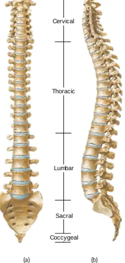
The unique arrangement of the different regions provides stability, resistance and elasticity to the spine, as well as the absorption of vibrations and/or impacts. There are four physiologic curvatures of the vertebral column in the sagittal plane, as illustrated in Figure 2.1.
Two of these curvatures are anteriorly convex in the cervical and lumbar regions (lordotic) and the other two are posteriorly convex in the thoracic and sacral regions (kyphotic). These curvatures and arrangements allow the spine to perform three different basic kinds of movements: the flexion/extension (forward/backward, respectively), lateral bending and axial rotation.
(a) (b)
Figure 2.1 - Views of the vertebral column, showing the different regions: (a) frontal view; (b) lateral view {Adapted from (Gray, 1918)}.
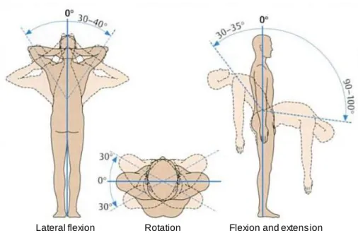
The possible movements of the spine, as well as the range of motion for each one, regarding the vertebral column as a whole are illustrated in Figure 2.2
Cervical
Thoracic
Lumbar
Sacral
Figure 2.2 – Mobility of the vertebral column: the extent of mobility from zero position (0°) is given in degrees {Adapted from (Faller et al., 2004)}.
Even though the cervical spine is the region with the wider range of motion, the thoracic segment allows primarily axial rotation and the lumbar region is the main responsible for flexion and extension movements. It is verified an increase of the flexion and extension range of motion from the first lumbar vertebra (L1) to the fifth (L5), and the lumbosacral joint (L5-S1) permits a wider motion in the sagittal plane than the other lumbar joints. Hence it is speculated that the high incidence of disc disease at the L4-L5 and L5-S1 levels is related to mechanical problems, as these two areas tolerate the highest loads and amount of motion in the sagittal plane (White and Panjabi, 1990). For this reason, the analysis performed in this work focuses on the lumbar spine, and Table 2.2 shows the limits and representative values of the ranges of rotation in this spinal region.
Table 2.2 – Limits and representative values of ranges of rotation of the lumbar spine {Adapted from (White and Panjabi, 1990)}.
Interspace
Combined
flexion-extension One side lateral bending One side axial rotation Range of rotation [deg] Representative angle [deg] Range of rotation [deg] Representative angle [deg] Range of rotation [deg] Representative angle [deg] L1-L2 5 - 16 12 3 - 8 6 1 - 3 2 L2-L3 8 - 18 14 3 - 10 6 1 - 3 2 L3-L4 6 - 17 15 4 - 12 8 1 - 3 2 L4-L5 9 - 21 16 3 - 9 6 1 - 3 2 L5-S1 10 - 24 17 2 - 6 3 0 - 2 1
2.1.1. The Vertebrae
Although the vertebrae of each spinal region have different characteristics, some features are common to all of them. The vertebra is composed by two main parts: a vertebral body and the posterior elements. Between these two parts exists a space called the vertebral foramen, through where the neural elements (e.g. the spinal cord) pass.
The vertebral body is the disc-shaped bony part in the anterior area of the spine and it is essential to withstand the compressive forces of the vertebral column. Two pedicles, bony parts between the superior and inferior surfaces of the vertebral body, project one from each side of it. Projecting backwards from each pedicle is a sheet of bone called lamina, and both laminae meet at a midline is the posterior part of the vertebrae. The assembly of the two pedicles and the two laminae forms an element called neural arch, as it surrounds the neural elements of the spine (as the spinal cord) and envelops the vertebral foramen, as visible in Figure 2.3(a).
(a) (b)
Figure 2.3 – Parts of a typical lumbar vertebra: (a) top view; (b) lateral view {Adapted from (Bogduk, 2005)}.
Other bony elements extend from the junction between lamina and pedicle: when directed upwards, this extension is called superior articular process; the downwards extension is called inferior articular process. Therefore, each vertebra has four articular processes: two on the right and other two on the left side. The medial surface of each superior articular process and the lateral surface for each inferior articular process are covered by articular cartilage and thus those regions are called the articular facets of the articular processes.
Neural arch Vertebral body Spinous process Lamina Superior articular process Lamina Superior articular process Transverse process Transverse process Pedicle Pedicle Pedicle Transverse process Spinous process Vertebral body
Each junction lamina-pedicle has another flat, rectangular process that extends laterally from it, called the transverse process, due to its orientation. Once again, each vertebra has a pair of these processes, which are used as attachment sites for ligaments and muscles.
Located on the most posterior part of the vertebral, after the midline junction of the two laminae, there is spinous process which is the element easily perceived through its protuberance under the skin of the back. As visible in Figure 2.3(b), this process merges imperceptibly with the laminae and it is an attachment point for muscles and ligaments.
All the vertebral components have an outer shell of hard, strong cortical bone whereas the inside is composed of soft, spongy cancellous bone.
Even though all the aforementioned elements are common to vertebrae from all the spinal regions, the lumbar vertebrae have some characteristics that are unique to this region, such as the mammillary and accessory processes, useful for muscle attachment.
After the lumbar vertebrae is the sacrum, an aggregate of five vertebrae fused with each other. It is the foundation for the pelvic girdle and the anterior and posterior sides of the sacrum contain four pairs of sacral foramina, through which nerves and blood vessels pass. The coccyx is composed by the fusion of the four coccygeal vertebrae. The top of the coccyx articulates with the sacrum.
(a) (b) (c)
Figure 2.4 – The sacrum: (a) frontal, (b) sagittal and (c) transverse view. Anterior sacral foramina (asf), remnants of the intervertebral disc (ivd), lamina (la), lateral mass (lm), superior articular process (sap), sacral canal (sc), sacral hiatus
(sh), spinous process of S1 (sp) and vertebral bodies (vb) {Adapted from (Bogduk, 2005)}.
2.1.2. The Intervertebral Disc
There are 23 intervertebral discs (IVD) in the vertebral column, between each pair of vertebrae from C2 to S1. Their deformable characteristics allow a small amount of movement in
lm vb asf sp sp sap la sc vb vb vb ivd sh
each spine level, but a large range of motion (from -30° to 90°, in the sagittal plane) when functioning simultaneously (Faller et al., 2004). Altogether, they represent 20-33% of the entire height of the spine and each one can be divided in three different parts (White and Panjabi, 1990): (i) the nucleus pulposus (NP), (ii) the annulus fibrosus and (iii) the cartilaginous vertebral endplates, as visible in Figure 2.5.
(a) (b)
Figure 2.5 - The intervertebral disc: (a) sagittal section and (b) transverse section {Adapted from (Bogduk, 2005)}.
The NP is the central area of the IVD and it is composed mostly by water in a matrix of collagen, proteoglycans and other matrix proteins. This water content is higher at birth (approximately 90%) and decreases to 80% at the age of 20 and to 70% at 60 years old. The NP has up to 65% of the dry weight in proteoglycans (proteins), several types of glycosaminoglycans (polysaccharides) and circa 15% of various types of collagen. There are still some cartilage cells in the NP, although in a concentration inferior to the AF and the endplates (Séguin et al., 2004).
The AF is a fibrocartilaginous element that encapsulates the NP and consists of 10-20 concentric lamellae of collagen fibers, in which those fibers are arranged parallel to each other. However, in each adjacent lamella the collagen fibers have different orientations: -30° with the vertical in a lamella and 30° in the adjacent lamella.
The cartilaginous endplates (present above and below each NP and AF) are hyaline cartilages that separate the NP and AF from the bony vertebrae.
2.1.3. The Lumbar Ligaments
The ligaments are elements with a complex architectural hierarchy that connect two or more bones. They are bands of fibrous connective tissue, composed mainly by water (55-65%). The remaining dry matter (35-45% of the total weight) is divided in 70-80% of collagen (type I), 10-15%
Nucleus pulposus Superior endplate Inferior endplate Annulus fibrosus Annulus fibrosus Posterior Anterior Nucleus pulposus Annulus fibrosus Annulus fibrosus
of elastin and 1-3% of proteoglycans. Figure 2.6 depicts the hierarchical organization of the ligament, showing the names and diameters of the different subelements.
Figure 2.6 – Hierarchical organization of the ligaments: names and diameters of the subelements {Adapted from (Herman, 2007)}.
Furthermore, the ligaments can be divided in two main categories: intrasegmental and intersegmental. The first group comprises ligaments that connect two bones and the second contains ligaments that join more than two bones (Boos and Aebi, 2008). Figure 2.7 shows a scheme that distributes the ligaments present in the lumbar spine for each of the abovementioned groups.
Figure 2.7 – Ligaments in the lumbar spine: division in intra- and intersegmental. Collagen Microfibril Ligament 50 -300 m m 50 -5 0 0 n m 3 .5 n m 1 .5 n m 10 -2 0 n m 100 -500 m m Fascicle Subfibril Fibril Fibre Crimp pattern Lumbar ligaments Intrasegmental Capsular Interspinous Ligament flava Intersegmental Anterior longitudinal Posterior longitudinal Supraspinous
As visible in Figure 2.7, from all of the spinal ligaments it is possible to highlight six types in the lumbar region: in the intrasegmental group, the capsular ligaments (CL), ligament flava (LF) and the interspinous ligament (ISL), and in the intersegmental group, the anterior and posterior longitudinal ligaments (ALL and PLL) and the supraspinous ligament (SSL). Figure 2.8 shows two adjacent lumbar vertebrae and the ligaments present between them.
Figure 2.8 - Medial sagittal section of two lumbar vertebrae and their ligaments {Adapted from (Gray, 1918)}.
It is possible to observe that the ligamentum flavum, an intersegmental ligament, only connects two adjacent vertebrae and, in the other hand, the posterior longitudinal ligament, an intrasegmental one, runs along the posterior surface of several vertebral bodies.
In order to simplify the understanding of the properties of each ligament, Table 2.3 summarizes the lumbar ligaments names, acronyms, anatomical areas connected and main functions (Behrsin and Briggs, 1988; Rogers and Jacob, 1992).
Table 2.3 – Lumbar ligaments: acronyms, anatomical areas connected and functions.
Ligament name Acronym Connects Functions
In te rs eg m en ta l Capsular CL Envelopes surrounding the facet
joints.
Resist axial rotation of the spine Interspinous ISL Roots of spinous processes of adjacent vertebrae Little resistance to forward bending spinal movements Ligamentum Flavum LF
Front surface of the laminae of adjacent
vertebrae
Resist excess separation of laminae
Table 2.3 – Lumbar ligaments: acronyms, anatomical areas connected and functions (continued).
Ligament name Acronym Connects Functions
In tr as eg m en ta
l Anterior Longitudinal ALL the vertebral bodies Anterior aspects of and IVD
Resists extension of the spine Posterior Longitudinal PLL
Posterior aspects of the vertebral bodies
and IVD
Resists separation of the posterior ends of the vertebral bodies Supraspinous SLL Posterior edges of the spinous processes
Little resistance to separation of the spinous processes
2.2. Spinal Disorders
Spinal disorders are a broad variety of diseases that affect the spinal components: the vertebrae, intervertebral discs, facet joints, ligaments and tendons, muscles, spinal cord and nerve roots of the spine. It is possible to classify these disorders in two groups, as noticeable in Figure 2.9: (i) the specific and (ii) the non-specific spinal disorders. The first group comprises 10-15% of all the reported disorders, and includes all those which are directly relatable to their source, such as congenital, developmental, traumatic, infectious, tumorous, metabolic and degenerative (the latter depends on the type of disorder). The non-specific spinal pain (cervical, thoracic or lumbar) belongs to the second group, involving 85-90% of the cases (Boos and Aebi, 2008).
Figure 2.9 – Spinal disorders: a division in specific and nonspecific disorders.
Various diseases that affect the vertebral column are usually painful and influence the patient’s everyday life.
Disc herniation is a leakage of the nucleus pulposus through a tear in the wall of the annulus fibrosus. This leakage presses on the local nerve root causing the pain. Tears in the wall usually occur due to aging and/or trauma.
Spinal Disorders Specific Congenital Development Traumatic Non-specific
Spinal stenosis is the narrowing of the spinal canal and can be caused by different conditions such as disc herniation, osteoporosis, or a tumor. Sometimes, and especially when the reason is a disc herniation, stenosis occurs at the same level of the disc.
Degenerative disc disease is the gradual deterioration of the disc causing loss of its functions. This disease usually develops with aging or from continuous activities that press on the disc space. It starts with a small injury in the annulus fibrosus causing damage to the nucleus pulposus and loss of its water contents. Further damage causes malfunctioning of the disc and thus collapsing the upper and lower vertebrae. As time passes, the vertebrae facet joints twist creating bone spurs that grow into the spinal canal and pinching the nerve root (stenosis).
Disc desiccation is the drying of the water contents in the inner pulposus. Usually, it is caused by aging and sudden weight loss.
Spinal infection occurs when a bacterial infection travels via the bloodstream into an intervertebral disc. This weakens the annulus fibrous, decays it, and might cause collapsing of the disc and thus pressure on the nerve root. Further infection might cause fusion of the enclosing vertebrae.
Degenerative Disc Disease
The degenerative disc disease (DDD) arises as a series of symptoms rather than a pathology by itself. However, the morphologic changes of the intervertebral disc throughout the degenerative process are evident macroscopically. Thompson et al. (1990) established a grading system in order to categorize the degeneration stage of the IVD. This classification comprises five stages, from grade I to grade V: (i) normal juvenile disc, (ii) normal adult disc, (iii) early stage, (iv) advanced stage, and (v) end stage. Figure 2.10 illustrates the different degenerative grades.
Figure 2.10 – Macroscopic disc changes due to DDD, according to Thompson’s classification: (a) grade I; (b) grade II;
Figure 2.10 – Macroscopic disc changes due to DDD, according to Thompson’s classification: (a) grade I; (b) grade II; (c) grade III; (d) grade IV; (e) grade V {Adapted from (Boos and Aebi, 2008)} (continued).
Regarding Thompson’s classification, a segmental flexibility study was performed by Fujiwara et al. (2000) and Tanaka et al. (2001). Human functional spinal units (FSU) with different grades of disc degeneration were mechanically tested through the application of moments in flexion/extension, axial rotation and lateral bending. The resultant three rotation angles of the superior vertebra relatively to the inferior fixed one were plotted. It was possible to conclude that the axial rotational motion was the most affected by degeneration, and that the segmental flexibility increased with the increase of the severity of disc degeneration until grade IV, but decreased from grade IV to grade V. Moreover, it was verified that segmental flexibility depends also on cartilage degeneration and gender.
Adams and Dolan (2005) analyzed the current trends in spine research and outlined the desirable areas for investigation. According to these authors, there should be a focus on understanding the interactions between IVDs and the adjacent vertebrae, as well as in the development of prosthetic and tissue-engineered discs, and in the quantification of the spinal function during rehabilitation. Within this perspective review, a study by Pollintine et al. (2004) was referred in which the degeneration of the IVD was associated with “stress shielding” of the anterior vertebral body, and possibly with one of the causes of osteoporotic vertebral fracture. Figure 2.11 shows the load sharing in the lumbar spine in erect posture. With a normal disc (Figure 2.11(a)), the neural arch resists only 8% of the applied compressive force and the rest is shared by the anterior and posterior areas of the vertebral body. However, in a situation of severe intervertebral
(c) (d)
disc degeneration (Figure 2.11(b)), the neural arch bears 40% of the load, leaving only 19% of the load in the anterior part of the vertebral body.
(a) (b)
Figure 2.11 – Load sharing and intervertebral disc degeneration: (a) normal disc; (b) degenerated disc {Adapted from (Pollintine et al., 2004)}.
Trauma in the Lumbar Spine
In 1983, Denis created a classification for thoracolumbar fractures that has been used since then by several authors. For this arrangement it was assumed that the vertebral column can be divided in three areas in the sagittal plane, as visible in Figure 2.12: the anterior (a), the middle (b) and the posterior (c) column.
Figure 2.12 – The three column spine: (a) anterior, (b) middle, and (c) posterior column {Adapted from (Denis, 1983)}.
The anterior column comprehends the anterior longitudinal ligament (ALL), the anterior annulus fibrosus (AF) and the anterior part of the vertebral body. The middle column includes the posterior longitudinal ligament (PLL), the posterior AF and the posterior wall of the vertebral body.
44% 48% 8% 19% 41% 40%
Finally, the posterior column is formed the neural arch and remaining ligaments (ligamentum flavum (LF) and capsular (CL), interspinous (ISL) and supraspinous (SSL) ligaments).
Regarding the nomenclature above defined, the types of fractures can be easily explained. As clarified in Figure 2.13, the major spinal injuries (the ones that cause acute spinal instability) are divided in four types: (i) compression fractures, (ii) burst fractures, (iii) fracture dislocations, and (iv) seat-belt type injuries.
Figure 2.13 – Major spinal injury types {Adapted from (Denis, 1983)}.
The biomechanics of the different injury types are as follows:
Compression fracture:
Failure under compression of the anterior column; Middle column remains intact.
Burst fracture:
Failure of the vertebral body under axial load, which results in failure of the anterior and middle columns both under compression;
Are further divided in fracture of both or only the superior or inferior endplates, burst rotation and burst lateral flexion.
Seat-belt type injuries:
Failure of both posterior and middle columns under tension forces generated by flexion;
Includes the one-level, through bone Change fractures.
Fracture dislocations:
Failure of all columns under compression, tension, rotation or shear.
From all the types, the compression fractures have the largest number of records, representing almost half of the cases. Understanding and quantifying the biomechanical changes inherent to these injuries is of great importance in the medical area, both from the solutions development point-of-view and the rehabilitation procedure.
Major spinal injury types
2.3. Solutions for Degenerative Disc Disease
In this section, some of the fundamental and common solutions to overcome degenerative disc disease (DDD) of the lumbar spine are presented. Most of the people who suffer from low back pain (LBP) have their problem solved with nonoperative treatments, such as the administration of anti-inflammatory medication, exercise, and physical therapy. However, when these solutions are not effective, an operative solution must be applied. Nowadays, there are three main techniques to treat DDD of the lumbar spine, as visible in Figure 2.14: (i) fusion, (ii) intradiscal electrothermal therapy (IDET), and (iii) disc replacement (An et al., 2003).
Figure 2.14 – Operative techniques for the treatment of lumbar DDD.
The fusion technique is used to join two or more vertebrae in order to reestablish structural integrity, to maintain correction after straightening of the spine or to prevent progression of an existing deformity, or even to diminish pain the constraining by the movement between various spine segments (White and Panjabi, 1990). There are several techniques used to perform fusion such as the so called posterolateral fusion with/without pedicle screw instrumentation, anterior/posterior lumbar interbody fusion, combined anterior and posterior fusion, cage devices, and minimally invasive techniques. Besides the wide range of choice among fusion techniques, there is no consensus in which is the best fusion procedure to follow. Furthermore, anomalies can happen with the lumbar spine fusion procedure. It can be seen increased/decreased motion, degenerative changes in the discs or facets, spinal stenosis, degenerative spondylolisthesis or even fracture dislocation.
The intradiscal electrothermal therapy (IDET) is indicated to treat pain originated from discs affected by radial fissures (Bogduk et al., 2005). The technique requires the introduction of a flexible electrode circumferentially around the interface between the annulus fibrosus (AF) and the nucleus pulposus (NP), with the goal of closing the radial fissure at its base through the delivery of heat that denervates the painful nociceptors (sensory receptor involved in the perception of pain)
Solutions for DDD
Compared to spinal fusion, the disc replacement approach maintains the motion between vertebrae but, as every prosthesis, the clinical results of the introduction of these devices are almost unknown, as well as their stability in a long-term application or the resistance of the components. There are some contraindications of the use of disc prosthesis, such as facet joint osteoarthritis (An et al., 2003). Nevertheless, the offer of disc replacement prosthesis is very broad, including various designs, material and customized characteristics developed in order to improve its function in the vertebral column. The subsequent paragraphs describe some of the lumbar disc replacement prosthesis available on the market.
Prosthetic Solutions
There are innumerous prosthetic solutions for spinal problems available in the market. In this overview, the focus is given to lumbar disc replacement prosthesis. There are four main companies that distribute this type of product, namely Spine Art, Synthes, FH Orthopedics and B|Braun. Figure 2.15 shows four lumbar disc replacement prosthesis produced by each one of the mentioned companies.
The Swiss company Spine Art developed Baguera © L, a titanium prosthesis for the replacement of the IVD, coated with a DIAMOLITH® carbon layer. It comprises a polyethylene nucleus that allows the surgeon to choose the mobility desired for the disc (SpineArt, 2011).
Prodisc-L ® is a product by Synthes Holding AG, headquartered both in Switzerland and USA. This implant has three parts: two cobalt-chrome-molybdenum (CoCrMo) alloy endplates with a plasma-sprayed titanium coating, and an ultra-high molecular weight polyethylene (UHWMPE) inlay. A 7-to-11 year follow up study has been conducted by the company showing good efficiency of the product in the treatment of degenerative disc disease (DDD) symptoms (SYNTHES, 2011).
A collaborative work of the FH Orthopedics with the Pitié Salpétrière Hospital in Paris, the French Atomic Energy Commission, the University of Paris 6 and OSEO Innovation resulted in the creation of LP-ESP ®. This prosthesis comprises two titanium alloy plates, separated by a deformable part (FHOrthopedics, 2011).
B|Braun Melsungen AG, a german medical and pharmaceutical company, developed activ® L, an implant whose main goals are to minimize the biomechanical stress at the facet joints and to avoid facet joint arthrosis in a medium- and long-term prospect (B|Braun, 2011). The plates are composed of a chromium-cobalt alloy and the inlay of viscoelastic ultra-high molecular weight polyethylene (UHMWPE) (Kyriacou and Yeh, 2009).
Figure 2.15 – Lumbar disc replacement prosthesis: (a) Baguera ® L, from Spine Art; (b) LP-ESP ®, from FH Orthopedics; (c) Prodisc-L ®, from Synthes; (d) activ® L, from B|Braun.
All the presented solutions aim to treat the DDD, reducing the discogenic pain and improving the patients function through the preservation of the motion in the affected vertebral level. However, the prosthetic solutions involve the removal of the diseased disc, converting this approach into a substitution rather than a treatment.
2.4. Summary and Discussion
In this Chapter, a description of the general anatomy of the spine was presented, focusing on the spinal regions and their functions, as well as the existent range of motion. Furthermore, a depiction of the spinal disorders was accomplished, centered on the set of pathologies which is in focus on this work, the degenerative disc diseases. Finally, some of the current solutions available on the market to solve this kind of problems were also depicted in this Chapter, showing that the answers to them can still evolve towards a biomimetic solution, rather than a substitution scenario.
(a)
(b)
(c) (d)
(a)
Chapter 3
Multibody Systems Formulation
3.1. Multibody System Concept
A multibody system is a set of rigid and/or flexible bodies connected by kinematic joints that constrain their large relative translational and rotational motion, and actuated by external forces (Nikravesh, 1988). The kinematic joints that can be present in multibody systems constrain the relative motion between the bodies connected by them, while the force elements represent the forces that are produced in the system, and between system and the surrounding environment.
Figure 3.1 illustrates a generic multibody system with its most significant components, namely bodies, joints and force elements.
Figure 3.1 – Generic representation of a multibody system.
The multibody systems formulation is a powerful tool in what concerns the study of the motion of a given system. As Figure 3.2 shows, it can either be used a kinematic or a dynamic approach for the analysis of a system.
Actuator Revolute joint Spherical joint Spring Body 1 Body n Body 3 Ground body Revolute joint with clearance Lubricated joint Contact bodies Applied torque Flexible body Gravitational forces Other applied forces
Body i