Vasco Pedro dos Anjos e Santos
DSAAR: Distributed Software Architecture
for Autonomous Robots
UNIVERSIDADE NOVA DE LISBOA
Faculdade de Ciˆencias e Tecnologia
Departamento de Engenharia Electrot´ecnica
DSAAR: Distributed Software Architecture
for Autonomous Robots
Vasco Pedro dos Anjos e Santos
Dissertac¸˜ao apresentada na Faculdade de Ciˆencias e Tecnologia da
Universidade Nova de Lisboa para obtenc¸˜ao do grau de Mestre em Engenharia
Electrot´ecnica.
Orientador:
Prof. Lu´ıs Correia
Elemento de ligac¸˜ao `a FCT/UNL:
Prof. Jos´e Barata
Acknowledgements
This dissertation has been supported by the Portuguese SME company IntRoSys, S.A.1.
First of all, I would like to express my gratitude to my dissertation supervisor, Prof. Lu´ıs Correia, to my colleague Pedro Santana, for all the valuable help, comments, advises, and support. My sincere appreciation to my colleagues at IntRoSys for all the relevant comments and support, namely: Carlos Cˆandido, Paulo Santos, M´ario Salgueiro, Luis Almeida and Jo˜ao Lisboa. Also thanks to Prof. Jos´e Barata for the opportunity and motivation.
I cannot forget my family, especially my parents, Maria Madalena Macieira dos Anjos and Victor Manuel dos Santos, for helping me become who I am today. I would also like to thank my friends for their support and enriching experiences. Most of all those who endured my journeys throughStyx,Acheronand other ofCharon’ssailing locations, you know who you are. AsAlbert Camussaid:
Don’t walk behind me, I may not lead. Don’t walk in front of me, I may not follow.
Just walk beside me and be my friend.
1www.introsys.eu
What is left when honour is lost?
Resumo
Esta dissertac¸˜ao apresenta uma arquitectura computacional desenhada de forma a permitir o r´apido desenvolvimento e prototipagem de sistemas multi-robˆos, denominada de Distributed Software Architecture for Autonomous Robots (DSAAR). Os blocos de construc¸˜ao da arqui-tectura DSAAR permitem ao engenheiros focar-se no modelo comportamental dos robˆos e do colectivo. Esta arquitectura ´e de especial interesse nos dom´ınios onde v´arios humanos, robˆos, e agentes computacionais tˆem de interagir de forma cont´ınua. Deste modo a r´apida prototipagem e a reutilizac¸˜ao s˜ao de maior importˆancia. A arquitectura DSAAR tenta lidar com estes requesi-tos de forma a alcanc¸ar uma soluc¸˜ao para o problema de n-humanos e m-robˆos com um cen´ario de boas pr´aticas de desenho e de ferramentas de desenvolvimento.
Esta dissertac¸˜ao tamb´em se ir´a focar ao n´ıvel das interacc¸˜oes Humano-Robˆo, especialmente no dom´ınio da teleoperac¸˜ao, onde o julgamento humano faz parte integral do processo, forte-mente influenciado pelos dados de telemetria recebidos do ambiente remoto. Logo a velocidade a que os comandos s˜ao enviados e os dados de telemetria s˜ao recebidos ´e de crucial importˆancia. Utilizando a arquitectura DSAAR ´e proposta uma aproximac¸˜ao de teleoperac¸˜ao, desenhada de forma a provendiciar a todas as entitades presentes na rede a noc¸˜ao de realidade partilhada. Nesta aproximac¸˜ao todas as entidades s˜ao fontes de conhecimento, numa abordagem semel-hante `a dodistributed blackboard. Esta soluc¸˜ao foi desenhada de forma a fornecer uma resposta em tempo real, assim como uma percepc¸˜ao o mais completa poss´ıvel do ambiente circundante ao robˆo. Os resultados experimentais obtidos com o robˆo f´ısico sugerem que o sistema ´e capaz de garantir uma interacc¸˜ao pr´oxima entre os utilizadores e o robˆo.
Abstract
This dissertation presents a software architecture called the Distributed Software Architecture for Autonomous Robots (DSAAR), which is designed to provide the fast development and prototyping of multi-robot systems. The DSAAR building blocks allow engineers to focus on the behavioural model of robots and collectives. This architecture is of special interest in domains where several human, robot, and software agents have to interact continuously. Thus, fast prototyping and reusability is a must. DSAAR tries to cope with these requirements towards an advanced solution to the n-humans and m-robots problem with a set of design good practices and development tools.
This dissertation will also focus on Human-Robot Interaction, mainly on the subject of teleoperation. In teleoperation human judgement is an integral part of the process, heavily in-fluenced by the telemetry data received from the remote environment. So the speed in which commands are given and the telemetry data is received, is of crucial importance. Using the DSAAR architecture a teleoperation approach is proposed. This approach was designed to pro-vide all entities present in the network a shared reality, where every entity is an information source in an approach similar to the distributed blackboard. This solution was designed to ac-complish a real time response, as well as, the completest perception of the robots’ surroundings. Experimental results obtained with the physical robot suggest that the system is able to guaran-tee a close interaction between users and robot.
Keywords: Multi-Agent Systems, mobile robots, software architectures, distributed architec-tures, teleoperation, human-robot awareness.
Symbols and Notations
Symbol Description
ACL Agent Communication Language AI Artificial Intelligence
API Application Programming Interface BDI Belief Desire and Intention
DARPA Defense Advanced Research Projects Agency
DSAAR Distributed Software Architecture for Autonomous Robots GPS Global Positioning System
HID Human Development Index HRI Human-Robot Interaction IPC Inter-Process Communications JADE Java Agent DEvelopment Framework
KB Knowledge Base
MAS-IM Multi-Agent System Interaction Mechanism
ms milisecond
PE Physical Entity
PDL Process Description Language SME Small Medium Enterprise USAR Urban Search And Rescue
Contents
1 Introduction 1
1.1 Problem Statement . . . 3
1.2 Solution Prospect . . . 5
1.3 Dissertation Outline . . . 7
1.4 Further Readings . . . 8
2 State-of-the-Art 9 2.1 Human-Robot Interaction Awareness . . . 9
2.1.1 Human-Robot Interaction Awareness . . . 10
2.2 Software Architectures and Reusable Software . . . 12
2.2.1 MARIE Architecture . . . 12
2.2.2 Claraty Architecture . . . 14
2.2.3 Retsina Architecture applied to mobile robots . . . 16
2.2.4 NASA’s Mobile Agents Architecture . . . 18
2.3 Pitfalls of the Current State-of-the-Art . . . 19
3 DSAAR Architecture 21 3.1 DSAAR: an architecture for Human-Robot teams . . . 21
3.1.1 Physical Constraints . . . 23
3.1.2 Multi-User Support . . . 24
3.1.3 Robots’ Computational Model . . . 24
xiv Contents
3.1.5 Process Layer . . . 26
4 Human-Robot Interactions under DSAAR 35 4.1 System Overview . . . 36
4.2 Interaction Semantics . . . 37
4.2.1 Inter-Agent Interactions . . . 38
4.2.2 Intra-Agent Interactions . . . 40
5 Situation Awareness Prototype 43 5.1 Global Perspective . . . 43
5.1.1 Mechanical Structure . . . 43
5.2 Mission Awareness . . . 46
5.3 Human-Robot interaction awareness . . . 48
5.3.1 TeleOperation Tool . . . 49
5.3.2 2D Map Tool . . . 50
6 Experimental Trials and Results 55 6.1 Multi-Platform Test . . . 55
6.1.1 Analysis . . . 56
6.2 Field Trials . . . 57
6.2.1 Experimental Setup . . . 57
6.2.2 Results and Analysis . . . 60
7 Conclusions and Future Work 63 7.1 Conclusions . . . 63
7.2 Future Work . . . 64
List of Figures
1.1 Multi-agent system architecture [Santana et al., 2005a] . . . 6
1.2 DSAAR General Overview . . . 7
2.1 MARIE’s application design framework [Cˆot´e et al., 2006] . . . 13
2.2 The CLARAty Architecture [Nesnas et al., 2006] . . . 15
2.3 The robot agent architecture enables robot integration in the RETSINA multi-agent system functional architecture by transforming physical robots into em-bodied task agents. [Nourbakhsh et al., 2005] . . . 17
2.4 NASA’s Mobile Agents Architecture: Mobile Agents entities and wireless net-work [Sierhuis et al., 2005] . . . 19
3.1 DSAAR Detailed Overview . . . 23
3.2 Physical Constraints . . . 24
3.3 multi-user System . . . 25
3.4 On-Board Computational Model. . . 25
3.5 Modules composing a process. . . 28
3.6 DSAAR message API structure. . . 31
4.1 Generic System Overview . . . 36
4.2 System Overview . . . 37
4.3 Inter-Agent Interaction. . . 40
xvi List of Figures
5.1 The Ares Robot prototype in Double Ackerman, Turning Point,
Omnidirec-tional, and Lateral Displacement modes. . . 45
5.2 Torsion around Ares’ spinal axle . . . 45
5.3 Ares Robot. . . 46
5.4 Mission Template . . . 47
5.5 2D Map Tool in mission support . . . 48
5.6 Snapshot of the TeleOperation Tool . . . 50
5.7 Snapshot of the 2D Map Tool. . . 52
5.8 Snapshot of the Log Builder Tool. The user may choose between one or more dates and build a mission log during that period of time. . . 52
5.9 Snapshot of the Map BuilderTool. Using this tool the user may insert a map of a determined region and by supplying its gps location and scale the operator may use it in a mission. . . 53
6.1 Platforms in which the DSAAR architecture has been tested . . . 56
6.2 Control Center . . . 58
6.3 Test field overview . . . 59
6.4 Test course main challenges’ . . . 59
6.5 Initial run (15x13 mxm). . . 60
6.6 Result of complete 5 seconds run (32x28 mxm). . . 61
6.7 Situation awareness in a 5 seconds run near point D (23x28 mxm). . . 61
6.8 Situation awareness in a 10 seconds run near point G (29x32 mxm) . . . 62
A.1 Registry and Communication sequence . . . 75
Chapter 1
Introduction
The motivation for the development of the Distributed Software Architecture for Autonomous Robots (DSAAR) is the current hand craft approach to robotics. Nowadays there is a lack of architectures that gather both computational and control models within the same framework. Usually scientific papers discard all implementation details, focusing solely on the control mod-els; robots are usually one-of-a-kind gadgets that are developed as the scientific contributions require.
However, as robot technology matured, it becomes highly relevant to develop tools focusing on the fast development and prototyping of multi-robot systems; only then mobile robots will be able to deal with fast market development, customisation, and reusability requirements. In this line of thought, the DSAAR architecture intends to provide the engineer and/or researcher with a set of design models and implementation tools to respond to these requirements.
DSAAR provides a computational model (e.g. object-oriented, agent-based) without com-mitting to any control paradigm (e.g. behaviour-based, deliberative). In the future it is expected to have some tools to instantiate DSAAR according to a set of given control models. Fur-thermore, it is shown that the computational model fits easily with the most relevant control models applied in mobile robots. It will also be shown that the architecture scales according to the available computational requirements. In fact, the separation between computational and control models allows the reusability of both models independently, making both contributions
2 Chapter 1. Introduction
valuable by themselves.
Other architectures, like CLARAty [Nesnas et al., 2006], Mission Lab [Endo et al., 2002] and MARIE [Cˆot´e et al., 2006] were not designed using the multi-agent paradigm, which make them less adequate for multi-robot systems as DSAAR intends to be. Moreover, usually archi-tectures commit to some control models. Conversely, DSAAR is implemented using the multi-agent paradigm and intends to be generic enough to handle any control model, like Behaviour-Based ones (e.g. [Brooks, 1986, Arkin, 1989, Santana and Correia, 2005] and Hybrid ones (e.g. [Konolige et al., 1997, Philippsen and Siegwart, 2003]).
DSAAR architecture is based on Linux inter-process communication (IPC) mechanisms and multi-agent Jade [Bellifemine et al., 2003, Website, 2006] software platform. The former al-lows interoperability between independent processes running within the same machine, whereas the latter extend this concept to multi-agents that can spread through all over the internet. The success measure of this architecture should be specified in terms of prototyping speed and code reusability. It was selected Linux and Jade because both can be used in commercial platforms even though they have open-source community support. A discussion was started about how much should the DSAAR commit to this open-source approach. Nevertheless, both Linux and Jade have LGPL licenses that allows proprietary software development.
DSAAR multi-agent approach also provides a study on Human-Robot interaction, mainly on the teleoperation subject. In teleoperation, as in any system involving humans, there is a clear need to map concepts between different representations. If one considers a shop floor the human notion of a specific movement, has to be mapped to the robots’ own representation of the world. It could be imposed a shared vision of reality, a common ontology, however the low-level notion of reality can not be described the same way as high-level notions are. Teleoperation poses the same problem, since the robots’ notion of its’ posture or telemetry has to be mapped into human readable information. When considering a system with heterogeneous entities, a common ontology becomes necessary in order to provide a common language to the system. Thus allowing the ability for the several entities to understand each other, when used.
1.1. Problem Statement 3
payload on the network excessive, due to telemetry data and teleoperation commands, thus placing them on a separate channel. This approach, does not feel the need of having the teleme-try data being represented through the hole network, rather choosing to have seldom points of direct mapping. In this work an approach that considers the telemetry data and teleoperation commands an integral part of the multi-agent systems’ network is purposed. As to allow a shared representation of all teleoperation orders and telemetry data.
This system was designed based on a collaborative network, it is assumed that every entity present in the network will work to the best outcome possible without any competition with other entities. This assumption allows for a simplification on the negotiation mechanisms, since there is no need to have elaborated trust mechanisms or partner selection mechanisms.
Another important issue in teleoperation is the perception the user has from the environment where the robot is, as well as, the robots’ posture are of crucial importance, as is real time vehicle control. It is reasonable to say that if the operator has not a real perception of the robots’ beliefs, e.g. posture or position, the operator can not decide where to lead the robot. The operator must also be able to perform manoeuvres in real time fashion, since any delay may render that manoeuvre useless.
1.1
Problem Statement
As previously stated, the goal of this dissertation is to develop an architecture that copes with the problem of working with heterogeneous systems. This problem has two main subjects, the robotic platform development problem and the human-robot interaction problem.
4 Chapter 1. Introduction
developing their own modules and not only the outputs. This becomes a problem for instance when developing the locomotion module, vehicles with different kinematics have to follow a similar structure which considering a track or a wheeled vehicle may difficult the developers work [Nayar, 2007].
Regarding the human-robot interaction problem, there are several important issues worth discussing, such as, the multi-user situation where the addition and removal of entities (e.g. supervisors, operators, robots, etc.) becomes a problem. The case study of this thesis is tele-operation. In teleoperation, as in many system involving humans and machines, there is a clear need to map concepts between different representations. This can be done by using a shared ontology to provide a common language among team members, thus allowing the ability for the entities to understand each other. For instance, robot’s sensor data must be mapped to a human readable set of symbols. Conversely, the human desired robot heading must be mapped into robot understandable symbols. The operator must also be able to perform manoeuvres in real time fashion, since any delay may render that manoeuvre useless, or even dangerous. This limits the type and amount of information to be mapped between human and robot. Some multi-agent teleoperation approaches [Nourbakhsh et al., 2005] have considered the load of telemetry and command messages on the network excessive thus placing them on a dedicated channel.
1.2. Solution Prospect 5
comply with the requirements presented above.
1.2
Solution Prospect
The DSAAR architecture development is part of the AMI-02 project, which aims the develop-ment of a multi-robot system for humanitarian demining (refer to [Santana et al., 2005a] for a more detailed information about the project).
There are a set of characteristics about the humanitarian demining domain that makes it suitable for multi-agent approaches (see [Santana and Barata, 2005] for a study on this issue). In particular:
• Landmines are widespread worldwide and usually located in most of terrains, which
re-quires that robots have to operate in highly heterogeneous environments. Usually this problem is tackled by the exploitation of heterogeneous robots specialised into a set of sensors and terrains. This means that the system’s configuration is highly knowledge intensive.
• Landmine detection is a highly complex process, which requires a lot of expertise. This
means that one may have many experts, operators, and machines operating in parallel though in cooperation. Thus, the system is distributed by nature.
• The small and closed nature of demining market requires companies to develop products
with high potential for technology transfer [Santana et al., 2005b]. Only then it is possible to guarantee return of investment. This means that the system must be fairly generalisable, reusable, and henceforth scalable.
All these characteristics lead to the definition of the multi-agent architecture illustrated in figure 1.1.
The architecture can be seen as composed of three layers, in which thephysical agents layer
6 Chapter 1. Introduction
Figure 1.1: Multi-agent system architecture [Santana et al., 2005a]
system, and to create images of robot’s world perspective so as to allow operators to observe what is happening in the field. Finally, thehuman agents layeris populated with key personnel involved in the operations, which interact with the system (i.e. software and physical agents) in timely fashion.
Robots in the physical agents layer must be endowed with a certain degree of autonomy, so as to guarantee at least safe navigation capabilities and payload sensory information man-agement. Software agents may be distributed over an arbitrary set of machines (e.g. PDAs), which can be dedicated for complex sensor fusion, human-machine interfaces, data logging, etc. Then, these agents communicate with each robot via an unified language (i.e. an ontol-ogy). The architecture must be flexible enough to allow the addition and removal of robots and software agents as required. Hence, there is an actual need for distributed multi-agent systems support, along with a need for hardware tightly coupled processes. Moreover, there is the need for an architectural basis that allow developers to scale the system as new robots or robot types are required, users access to the system, etc. Hence, there is a clear need for the system to be evolvable.
In reality DSAAR has been designed so that there is no privileged point to look to and out of the system. Thephysical agents, thesoftware agentsand thehuman agentsare all considered
1.3. Dissertation Outline 7
Figure 1.2: DSAAR General Overview
a video camera which can be seen as an autonomous agent requesting services of the robotic platform for displacing itself. Entities that represent a physical being can also be called of emphphysical entity. Each entity interacts mainly through anagent, a general representation of the system is depicted in figure 1.2.
In this architecture each entity is considered a knowledge source, fostering a shared rep-resentation of each entities beliefs, desires and intentions (BDIs), resembling the distributed blackboard architecture [Nolle et al., 2001]. This approach enables a shared representation of all teleoperation orders and telemetry data through the system. Considering that each entity has its own perception on the reality, a shared representation must be imposed, in order to al-low a common way of interaction, i.e. an ontological commitment [Grosz and Kraus, 1999], [Cohen and Levesque, 1991], [Grosz and Kraus, 1996] (see Figure 1.2).
Contrary to other approaches, such as [Nourbakhsh et al., 2005], that have a dedicated chan-nel through which all teleoperation commands and telemetry messages are exchanged, in the DSAAR architecture all the teleoperation related information flows in the MAS network. Work-ing with a shared network approach forced the information exchange to be optimised.
Hence, the goal of the DSAAR architecture is to provide the fast development and proto-typing of multi-robot systems, as well as, a real time HRI awareness.
1.3
Dissertation Outline
This dissertation is organised as follows:
8 Chapter 1. Introduction
Chapter 3 presents the DSAAR architecture.
Chapter 4 proposes an approach to the teleoperation problem using the DSAAR architecture
Chapter 5 presents an instantiation of the DSAAR architecture to the problem of Human-Robot interaction in all-terrain environments.
Chapter 6 presents the field trials done with the physical robot in order to test this presented approach.
Chapter 7 aggregates a set of conclusions, main contributions of this dissertation, and further research opportunities on the subject.
1.4
Further Readings
Chapter 2
State-of-the-Art
This chapter surveys the state-of-the-art on human-robot interaction awareness, on software architectures and reusable software.
Software architectures and reusable software provide insight into the main problems while developing generic software which is meant to be used in different robots. Whereas human-robot interaction awareness provides a closer look to the problems that humans have while interacting with the physical robots.
2.1
Human-Robot Interaction Awareness
Regarding Human-Robot Interaction (HRI) awareness semantics there is a lack of standards on the terms used to describe the several types of awareness, as it is described in the work of Drury et al. [Drury et al., 2003]. In that work Drury et al. expose several contradictions in the defini-tion of the terms used, e.g. awareness is defined as “an understanding of the activities of others, which provides a context for your own activities.” by Dourish et al. [Dourish and Belloti, ] and as “given two participantsp1 andp2 who are collaborating via a synchronous collaborative
ap-plication, awareness is the understanding that p1 has of the identity and activities of p2.” by
Drury [Drury, 2001]. In their work Drury et al. [Drury et al., 2003] purpose a framework in order to classify HRI awareness regarding thenhumans andmrobots scenario.
10 Chapter 2. State-of-the-Art
HRI awareness (general case): Given n humans andm robots working together on a syn-chronous task, HRI awareness consists of five components:
Human-Robot the understanding that the humans have of the locations, identities, activities, status and surroundings of the robots. Further, the understanding of the certainty with which humans know the aforementioned information.
Human-Human the understanding that the humans have of the locations, identities and activ-ities of their fellow human collaborators.
Robot-Human the robots’ knowledge of the humans’ commands needed to direct activities and any human delineated constraints that may require command non-compliance or a modified course of action.
Robot-Robot the knowledge that the robots have of the commands given to them, if any, by other robots, the tactical plans of the other robots, and the robot-to-robot coordination necessary to dynamically reallocate tasks among robots if necessary.
Humans’ overall mission awareness the humans’ understanding of the overall goals of the joint human-robot activities and the measurement of the moment-by-moment progress obtained against the goals. In recent work [Drury et al., 2007] this concept is simply calledoverall mission awareness.
2.1.1
Human-Robot Interaction Awareness
2.1. Human-Robot Interaction Awareness 11
be able to perform manoeuvres in real time fashion, since any delay may render that manoeuvre useless, or even dangerous. This limits the type and amount of information mapping. From the humans point of view there are several ways of providing perceptual clues (e.g. maps, video, etc.). In some work the robots’ posture has been included in the video feed [Wang et al., 2004], also the ability of providing a camera with autonomous control has proved to improve the op-erators’ awareness [Joeseph Manojlovich and Gennari, 2003]. The joint use of video and maps has been proved useful by the work of Nielsen and Goodrich [Nielsen and Goodrich, 2006], where several combinations have been tested.
Taking these factors into account Dury et al. [Drury et al., 2007] suggest a series of cate-gories that should be taken into account.
Location Awareness was defined as map-based concept: orientation with respect to land-marks. If an operator was unsure of his or her location, this constituted negative location awareness.
Activity Awareness pertained to an understanding of the progress the robot was making to-ward s completing its mission, and was especially pertinent in cases where the robot was working autonomously. The human needed to know what the robot was doing at least so that he or she understood its part of the mission.
Surroundings Awareness pertained to obstacle avoidance: someone could be quite aware of where the robot was on a map but still run into obstacles. An operator was credited with having positive surroundings awareness if he or she knew that they would hit an obstacle if they continued along their current path.
12 Chapter 2. State-of-the-Art
2.2
Software Architectures and Reusable Software
This section presents some of the most relevant software architectures, namely the MARIE architecture, NASA’s CLARAty architecture, NASA’s mobile agents architecture and Retsina architecture applied to mobile robots.
2.2.1
MARIE Architecture
MARIE [Cˆot´e et al., 2006] is a middleware framework oriented toward s developing and inte-grating new and existing software for robotic systems. MARIE is designed according to three main software requirements: (1) Reuse available solutions, (2) Support multiple sets of con-cepts and abstractions, (3) Support a wide range of communication mechanisms and robotics standards. In order to accomplish this, MARIE is based on three design choices:
Component Mediation Approach uses a Mediator Interoperability Layer (MIL), this creates a centralized control unit (the Mediator) that interacts with each colleague (component) independently, and coordinates global interactions between colleagues to realize the de-sired system. In the MIL, components can interact together using a common language. Using this approach each component can have its own communication protocol and mech-anism as long as the MIL supports it. This is done, in order to, exploit the diversity of communication protocols and overcome the absence of standards in robotic software sys-tems. It also promotes loose coupling between components by replacing a many-to-may with a one-to-many interaction model.
2.2. Software Architectures and Reusable Software 13
Figure 2.1: MARIE’s application design framework [Cˆot´e et al., 2006]
useful tools to build and manage integrated applications using available components, to craft robotic systems.
Communication Protocol Abstraction eases components interoperability and reusability by avoiding fixing the communication protocol during the component design phase. This choice should be made as late as possible, depending of which components need to be interconnected together (e.g. at the integration phase or even at runtime). Therefore, a communication abstraction framework, called port, is provided for communication pro-tocols and component’s interconnections.
A generic framework of MARIE’s architecture can be seen in figure 2.1, there one can see how different applications interact through the MIL. It also shows how when an application which uses a communication protocol which is not supported by MARIE, is integrated through the Communication Adapter.
14 Chapter 2. State-of-the-Art
2.2.2
Claraty Architecture
CLARAty [Nesnas et al., 2003], [Nesnas et al., 2006] is a domain-specific robotic architecture designed with four main objectives: (i) to reduce the need to develop custom robotic infrastruc-ture for every research effort, (ii) to simplify the integration of new technologies onto existing systems, (iii) to tightly couple declarative and procedural-based algorithms, and (iv) to operate a number of heterogeneous rovers with different physical capabilities and hardware architectures. The CLARAtyarchitecture has two distinct layers: the Functional Layer and the Decision Layer. The Functional Layer uses an object-oriented system decomposition and employs a num-ber of known design patterns [Gamma et al., 1995] to achieve reusable and extendible compo-nents. These components define an interface and provide basic system functionality that can be adapted to a variety of real or simulated robots. It provides both low- and mid-level autonomy capabilities. The Decision Layer couples the planning and execution system It globally reasons about the intended goals, system resources, and state of the system and its environment. The Decision Layer uses a declarative-based model while the Functional Layer uses a procedural-based model. Since the Functional Layer for predicted resource usage, state updates, and model information.
The Decision Layer accesses the Functional Layer at various levels of granularity (figure 2.2). The architecture allows for overlap in the functionality of both layers. This intentional overlap allows users to elaborate the declarative model to lower levels of granularity. However it also allows the Functional Layer to build higher level abstractions (e.g. navigator) that provide mid-level autonomy capabilities. In the latter case, the Decision Layer serves as a monitor to the execution of the Functional Layer behaviour, which can be interrupted and pre-empted depending on mission priorities and constraints.
The Functional Layer The Functional Layer includes a number of generic frameworks cen-tred on various robotic-related disciplines. The Functional Layer provides the system’s low-and mid-level autonomy capabilities. The Functional Layer has four main features:
2.2. Software Architectures and Reusable Software 15
Figure 2.2: The CLARAty Architecture [Nesnas et al., 2006]
The Functional Layer separates algorithmic capabilities from system capabilities.
It separates the behavioural definitions and interactions of the system from the implementation.
the Functional Layer provides flexible runtime models. The runtime model is part of the abstraction model, of which, one part is associated with the generic functionality and the other with the adaptation.
The Decision Layer The Decision Layer is a global engine that reasons about system re-sources and mission constraints. It includes general planners, executives schedulers, activity databases, and rover and planner specific heuristics. The Decision Layer plans, schedules, and executes activity plans. It also monitors the execution modifying the sequence of activities dynamically when necessary. The goal of a generic Decision Layer is to have a unified repre-sentation of activities and interfaces.
16 Chapter 2. State-of-the-Art
capabilities and combine them in ways not provided by the Functional Layer.
Discussion Claraty is a domain applied architecture, space exploration, and so it does not take into account issues like real-time human-robot interaction (e.g. teleoperation). Also this architecture forces a very strict design structure, so it narrows the developers design choice (i.e. it difficults the implementation of a biological approach). This approach is designed for an autonomous robot, so it does not take into account any interactions with other entities within the system.
2.2.3
Retsina Architecture applied to mobile robots
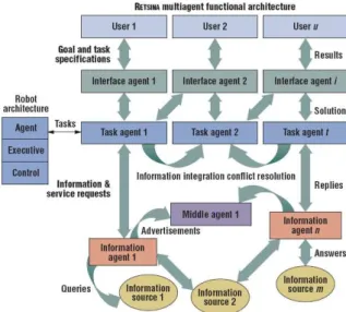
This approach integrates a Multi-Agent Systems architecture, RETSINA [Sycara et al., 2003], in a multi-robot scenario [Nourbakhsh et al., 2005]. RETSINA categorizes agents into four types based on their function: (1) Interface agents, which facilitate user interaction; (2) Task agents, that seek to accomplish user goals; (3)Middle agents, which provide infrastructure for dynamic runtime discovery of robots and agents that can perform a given task; (4)(Information agents), that can access external information sources, such as disaster site blueprints.
2.2. Software Architectures and Reusable Software 17
Figure 2.3: The robot agent architecture enables robot integration in the RETSINA multi-agent system functional architecture by transforming physical robots into embodied task multi-agents. [Nourbakhsh et al., 2005]
layer encapsulates the physical robot behaviour implementation. This representation combines the functional abstraction of standard three tier architectures with a high-level semantic ab-straction that transforms the robot into a robot agent suitable for conventional software agent coordination and cooperation.
18 Chapter 2. State-of-the-Art
Discussion This approach is focused on HRI, where the MAS is used to provide an interaction pool for the several ’agents’ present on the network. However this approach considers the load occupied by ACLs due to telemetry data and teleoperation commands on the network excessive, thus placing them on a separate channel. Meaning that only high-level interactions are contemplated with this approach, such as plan sharing.
2.2.4
NASA’s Mobile Agents Architecture
NASA Ames’ Mobile Agents Architecture (MAA) [Sierhuis et al., 2005] is a distributed agent-based architecture, which integrates diverse mobile entities in a wide-area wireless system for lunar and planetary surface operations. The MAA is a distributed agent architecture developed in Brahms. Brahms is a multi-agent rule-based BDI language developed at NYNEX S&T, IRL and NASA Ames. The Brahms environment consists of a language definition and compiler, a graphical development environment (the Composer) and a Brahms virtual machine (the BVM), running on top of the Java virtual machine, to load and execute Brahms agents.
2.3. Pitfalls of the Current State-of-the-Art 19
Figure 2.4: NASA’s Mobile Agents Architecture: Mobile Agents entities and wireless network [Sierhuis et al., 2005]
Discussion This architecture is designed for high-level interactions, in order to coordinate off world planetary explorations. The Brahms agents are responsible for the interactions between the several entities in the system, however due to the intention of this architecture it does not take into account real time interactions. Also interactions are very specified, which reduces the ability of entities interaction with each other (e.g. the EVA astronaut can only interact with the HabCom through the EVA robot).
2.3
Pitfalls of the Current State-of-the-Art
Chapter 3
DSAAR Architecture
In this chapter the Distributed Software Architecture for Autonomous Robots(DSAAR) will be presented. Afterwards a general overview of the architecture will be presented. Finally the the physical entity (robot) module will be presented. For a description on the enabling technologies please refer to appendix A.
3.1
DSAAR: an architecture for Human-Robot teams
The coordination problem betweenhuman teamsandrobot teamshas been one of the main con-cerns in Urban Search And Rescue (USAR), due to communication difficulties and the hetero-geneity of the several agents involved in this process, as it shown by [Burke and Murphy, 2004], [Nourbakhsh et al., 2005].
The Distributed Software Architecture for Autonomous Robots (DSAAR) architecture , is presented as a solution to this problem. DSAAR is implemented under the multi-agent paradigm and intends to be generic enough to handle any control model. Although this architecture has been designed to support robot teams, this could not yet be tested as the preparation of the robotic team is still an ongoing activity.
DSAAR architectures’ social awareness is supported by the multi-agent Java DEvelopment Framework (JADE) software platform, which allows interoperability between the robot teams
22 Chapter 3. DSAAR Architecture
and the human teams. JADE is a Multi Agent System platform, which complies with the FIPA specifications. By being compliant with FIPA standard, JADEs’ communication language is based in Agent Communication Language (ACL).
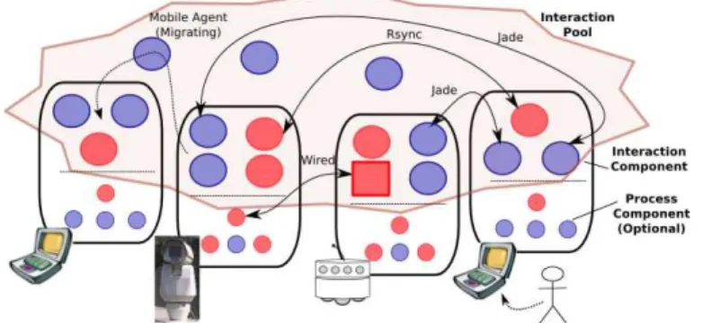
DSAAR has been designed so that there is no privileged point to look to and out of the sys-tem. For instance, a robot can be wired to a camera in order to synchronize a certain behaviour (e.g. something blocking the robots’ movements), yet the camera can also be interacting with a human user who is using it for teleoperation. The several units that compose the system have been calledphysical entities. A physical entityrefers to any physical device that exhibits some autonomous behaviour. For instance, aphysical entitycan be either a human interacting through a laptop, a robot, or even any other device that could be seen and endowed with some autonomy. An example is a video camera which can be seen as an autonomous agent requesting services of the robotic platform for displacing itself. Each entity is composed by interaction componentsandprocess components, as it is shown in figure 3.1. In this figure it can be seen two different kinds of components, some are native to the machine (pink ones) and others are in a java virtual machine in the JADE platform (purple). These components can be from data feeders up to agents, depending on their complexity level. Agents can either be found at the
interaction componentsorprocess componentslayers, some implemented in JADE others in a native language.
Process components refer to the those responsible for the direct control of a physical en-tity’s resources. These components are for exclusive use of the entity and are not used in any interaction mechanism.
Interaction components refer directly to the Human-Robot teams problem. It describes all the possible interactions between the several entities requiring a computational backbone. This goes to say that models which do not need direct communication, are not, and do not need, to be represented.
3.1. DSAAR: an architecture for Human-Robot teams 23
Figure 3.1: DSAAR Detailed Overview
To transfer large amounts of data, such as the mission full log, tools for incremental syn-chronisation, such asrsyncorftp, of the files located in the robot to a remote logging machine are being employed. This way the data flow in the network is minimised. Since it allows direct communication between entities and removes any extra unneeded processing, a direct video link over IP for video streaming is preferred to any other option. The transfer of agents is also considered as a kind of interaction. It allows migrations of agents for the necessary entities, enabling an increased efficiency in resource management. This can be seen in figure 3.1.
3.1.1
Physical Constraints
24 Chapter 3. DSAAR Architecture
Figure 3.2: Physical Constraints
which require a careful reliability analyses in order to avoid single point of failures.
3.1.2
Multi-User Support
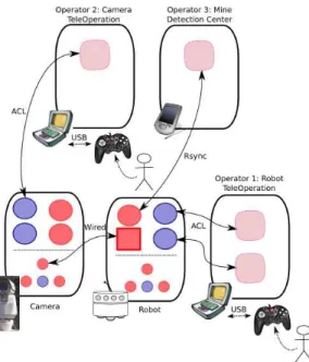
Considering previous work in the Human-Robot teams issues, the advised ratio for robot control is of 2:1 [Burke and Murphy, 2004]. Another recommendation is if a third user is added to the equation, this user should focus on a specific issue. To this effect some tools were developed. Let us considered the example given in figure 3.3. In this figure one can see the operator 1
teleoperating the robot with help of a tool (represented as a square in the operators entities); and another one controlling the camera using the same tool, yet in a different mode and in a different laptop. Thus, each operator is allowed to focus on a specific task. Then, a third operator, like a landmine expert that is only focused in finding mines, can log into the system via a remote machine for data analyses without disturbing the team-mates.
3.1.3
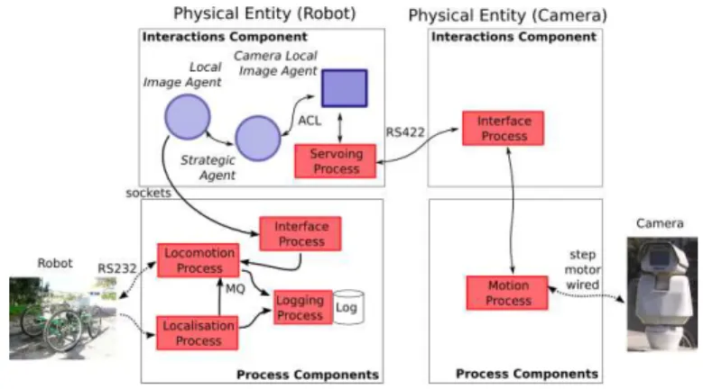
Robots’ Computational Model
Figure 3.4 illustrates the two main software layers on-board each robot. Theinteraction layer
refers to the social ability and configurability of the system, whereas theprocess layer controls everything related to robot navigation and hardware resources management.
3.1. DSAAR: an architecture for Human-Robot teams 25
Figure 3.3: multi-user System
26 Chapter 3. DSAAR Architecture
3.1.4
Social Layer
Thesocial layeris based on the Jade multi-agent platform, which handles inter-agent commu-nication in a transparent way, whether agents are in the same or in different machines. Com-munication among agents follows a well specified ontology. DSAAR defines for this layer the following roles:
• Implementation of collective behaviours, i.e. behaviours requiring interactions between
different robots;
• Interface between robot control software and middle layer agents;
• Fast prototyping of robot control behaviours; notice that Java may induce considerable
latency in cycle times and so control behaviours in Jade have to be considered in a very careful and temporary way.
As previously referred, agents can be located in any machine, can even be moved from one machine to another. This allows a fast reconfiguration and adaptability of the system. For instance, agents can be moved to the machine as the behavioural model requires. This also allows to have agents distributed as computational resources become available, distributing the load. In addition, agents can be launched in different machines (e.g. in a PDA or in a remote internet connection) and connected to a specific robot on the fly.
Hence, Jade makes DSAAR a highly versatile architecture. However, Java agents can not implement robot control algorithms. This is delegated to theprocess layer. In fact, a sockets-based API (Application Programming Interface) has been developed to allow the interaction between Jade agents and Linux processes, which are running at theprocess layer. This API is responsible for translating Java objects into C structures and vice-versa.
3.1.5
Process Layer
3.1. DSAAR: an architecture for Human-Robot teams 27
with one or more of the following roles, depending on the control model:
• Sensor Process. A process responsible for fetching sensory data, pre-process it, and send
the results to other process(es) via an IPC (Inter-Process Communication) mechanism (e.g. Shared Memory, Message Queues). In other words, the output message of such a process is a percept, which can be piled up in a Message Queue or stored in a shared memory associated to a time stamp.
• Actuator Process. A process responsible for acting in actuators according to incoming
IPC messages, produced by other processes;
• Behaviour Process. A process responsible for achieving a particular goal of the robot
according to incoming data from other processes (e.g. sensory or otherbehaviours) and forwarding data to other processes (e.g. actuators). This is responsible for the implemen-tation of the robot’s control logic. In particular a behaviour process, can be a reactive computational unit, a deliberative one, or whatever. The granularity of the semantics associated to each process is left to the control model and no assumptions are made at the computational model level. Nevertheless, as it is possible to see, the provided com-putational semantics is already driven by well established control model concepts, like behaviours and precepts.
• Interface Process. A process responsible for interfacing different systems, like Jade
agents and Linux-Based processes. These processes are really important to integrate legacy systems, ad-hoc developments, and even software implemented in different hard-ware (e.g. interfacing a two PCs through a serial port), which may be useful to fulfil real time constraints.
28 Chapter 3. DSAAR Architecture
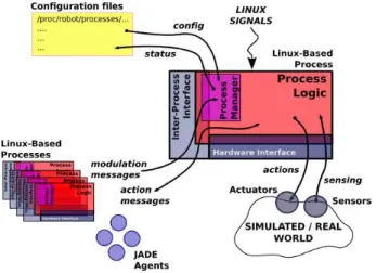
Figure 3.5: Modules composing a process.
Process Logic
This module is responsible for implementing all the logic corresponding to the process be-haviour. That is to say that the process logic may a sensory-motor module, a deliberative mod-ule, a behaviour coordination node, a sensory input signal processing algorithm, etc.
Therefore, the process logic semantic definition is to be instantiated as specified by the control model, whereas the computational model is concerned about the way modules interact among themselves. For instance, the process logic which is mainly concerned with control and navigation aspects will have to interact with data provided by hardware, configuration files, and other processes. These interfaces are well defined, supported by an API, and overviewed below. The internal structure of the process logic is not covered in this paper.
Inter-Process Interface
3.1. DSAAR: an architecture for Human-Robot teams 29
can change the processes generating messages as long as they respect the common semantics. Currently message semantics is specified by C structures. In the future it is planned to full specify messages as an OWL (Web Ontology Language) [OWL Website, 2006] ontology, which allows to use tools like Prot´eg´e OWL plug-in [Protege OWL Website, 2006] for their proper manipulation. As it will be shown below, in some IPC mechanisms this would be easy to implement, such as in those string based. However, others require a well C structure spec-ification, which would require a way of translating OWL specifications into C structures and respective compilation.
The following mechanisms are considered in DSAAR:
• Shared Memory. Of special interest for large data blocks transfer. The absence of a
built-in ”event” generating mechanism, requires from processes to poll for new messages. Linux semaphore mechanisms can be employed to ease this interaction;
• Message Queues. Messages are described as C structures, discarding the need for string
parsings, as in the previous and subsequent cases. Messages trigger events and so pro-cesses do not need further synchronisation or polling mechanisms. It is possible to send messages to different clients by specifying the type of the message. However, there is a limited number of messages that can be flowing simultaneously.
• FIFO. Similar to Linux pipes, i.e. special files where processes can write and read
mes-sages. This mechanism also requires parsing and special care with messages with differ-ent sizes.
• Sockets. Sockets are of special use to interact with Java processes. Drawbacks related to
string based communication.
30 Chapter 3. DSAAR Architecture
to/from other processes via any IPC mechanism in a transparent way. As explained earlier the goal is to have OWL message specifications, which will try to automate this process; still, some studies have to be carried out in terms of computational overhead.
All messages have a time stamp associated, which is an absolute time in micro-seconds, cor-responding to the event associated to the message (e.g. the time of a sensor acquisition process), and not to the sending or receiving time of the message. This allows a proper manipulation of incoming messages, which is of special interest for sensor fusion.
The goal of the architecture is to allow the developer to focus on the process logic. To do that, the designer only has to take into account that the process will require a set of inputs and outputs, through which messages flow. Thus, both the sender and the receiver must only know how messages are built.
Let us now detail the currently implemented messages API. For each message flowing in the system that has to be two corresponding xxxmsg.handxxxmsg.cfiles. These files publish the following two major entities:
• A C structure whose fields specify the message body (e.g. heading), the time-stamp of
the message, and in some cases the identification of the target client. This structure is to be filled in by the sender and read by the receiver.
• Two functions to convert a string into a structure and vice-versa.
Message senders and receivers only have to include these files so as to abstract the messages’ transmission medium. The medium through which a message is sent is not set in the referred files nor in the process logic. In fact the transmission medium (e.g. message queues) is set along the message recipient in a configuration file (see above explanations about this issue).
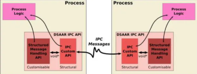
Figure 3.6 illustrates the internal structure of the implemented API. As it is possible to depict from the figure, the structural API (i.e. ipc.c) handles messages without being aware of their structure (i.e. semantics). This API handles void∗ messages. Then, the message customised
3.1. DSAAR: an architecture for Human-Robot teams 31
Figure 3.6: DSAAR message API structure.
above. The control logic can interact with both. Preferentially, if a customised message API exists, then it should be used.
The structural API (i.e. ipc.c) is mainly composed of functions to manage IPC shared re-sources (e.g. creation) and to send and receive messages. These latter features depend on the IPC type (e.g. shared memory, message queue), the client identification, the IPC resource Key (i.e. unique ID), and the message itself. If the type is message queue then the message is the structure specifying it; otherwise the message is a string describing it, which has been translated by a customised API (i.e.xxxmsg.c).
Process Manager
Theprocess manageris thread internal to each process. The process manager is responsible for making the process compliant with DSAAR. Other processes can send dedicated IPC messages to the process manager (i.e.modulatetype messages) to:
• Allocate memory. This message asks the process manager to allocate and register all
required IPC resources.
• Start/Stop/Resume the process.Self explanatory. This is different from sending a Linux
signal to perform these operations. In this case the process logic can be stopped while other activities still running, like logging.
• Change cycle time. Changing cycle time is different from changing priority. When one
32 Chapter 3. DSAAR Architecture
time refers to the time spent without doing nothing before starting a new cycle, indepen-dent of the processing ”speed”.
• Inhibit IPC input messages. Inhibition of messages can be used for both debugging and
as a part of the behavioural model.
• Suppress IPC output messages. Suppression of messages can be used for both
debug-ging and as a part of the behavioural model.
Thus, the process manager, among other functions, it is responsible for maintaining an in-ternal structure with the info received by themodulatemessages. Then, the process logic shall comply with these modulation signals, like sleeping after a cycle so as to cope with the cycle time requirements.
This modulation mechanism is generic enough to allow:
• Synchronisation of several processes according to a general intent;
• Modulation of the activity of each process according to some events (either exterioceptive
or proprioceptive).
Notice that modulate type messages are received and sent through the IPC DSAAR API, as any other message; hence, a process output can easily be configured to modulate other pro-cesses, which is a very important feature. It is common in robotic architectures to have processes modulated according to the current world and internal state. For instance, computational load of certain perceptual processes can be reduced according to some heuristics about the environ-ment.
3.1. DSAAR: an architecture for Human-Robot teams 33
General Procedure
Basically, the current procedure of developing, configuring, and launching a network of pro-cesses is roughly as follows:
1. The developer implements all the processes and corresponding IPC specific code (e.g. message structures);
2. The/var/robot/tree is updated to handle these new type of processes;
3. Interactions among processes (e.g. who receives and sends messages) are specified in an
interactionsfile according to the robot’s goal and behavioural model;
4. Specific process configurations are set inconf ig files according to the robot’s goal and behavioural model;
5. A script starts all processes according to interactionsfile, i.e. by taking into account their priorities;
6. Theprocessmanagerreads all configuration and interaction files so as to allow the pro-cess logic to operate conveniently;
7. The manager also finds the nice and PID info and update the corresponding files;
8. A central process sends amodulatemessage to all processes requesting them to allocate all IPC resources;
9. The same process asks then all processes to start operations;
10. Processes interact among themselves via IPC messaging as their control logic requires;
11. Processes generate status information which is set instatusandlog files;
34 Chapter 3. DSAAR Architecture
Chapter 4
Human-Robot Interactions under DSAAR
In this chapter it is presented the approach taken regarding to HRI. Here a more detailed ex-planation is given on how each entity interacts with each other and also with itself. In order to test this approach two tools were designed: the teleoperation tool and the 2D map, whose functionalities will be described in chapter 5. In this chapter the way in which these tools work is explained. Exposing the form in which the human (e.g. operator) interacts with the robot and all the necessary steps for it to happen.
Contrary to other approaches [Nourbakhsh et al., 2005], this thesis proposes an approach where teleoperation commands and telemetry messages have no dedicated channel. Having all teleoperation related information in the main MAS network, lead to an approach where all this information is shared on the network. In this multi-agent system network each entity is considered a knowledge source, fostering a shared representation of each entities beliefs, desires and intentions (BDIs), resembling the distributed blackboard architecture [Nolle et al., 2001]. This approach enables a shared representation of all teleoperation orders and telemetry data through the system.
Having all teleoperation information flowing through the MAS network causes a higher load on the network, forcing the information exchange to be optimised. A study on this subject is also shown in chapter 6, as to see if this shared reality approach promotes an improved operators situation awareness, as well as, of other entities added to the system.
36 Chapter 4. Human-Robot Interactions under DSAAR
Figure 4.1: Generic System Overview
Section 4.1 presents the teleoperation model, exposing the different components and enti-ties present in the system, design approaches and assumptions. Then, the computational model, where the different interactions semantics used by the agents during their interaction are ex-plained, is presented in section 4.2.
4.1
System Overview
Considering that each entity has its own perception on the reality, a shared representation must be imposed, in order to allow a common way of interaction, i.e. an ontological com-mitment [Grosz and Kraus, 1999], [Cohen and Levesque, 1991], [Grosz and Kraus, 1996] (see figure 4.1).
This dual reality representation is implemented as part of the architecture described in the previous chapter. These two reality representations are needed in a similar way as humans use it, when humans interact with each other they use language, while interacting with themselves hormones and other stimuli may be used. This allows the entity to have real-time responses con-cerning itself and lesser time dependent responses while interacting with others. The proposed system was designed based on a network inhabited by cooperative agents, i.e. all contribute for the global good. This assumption allows for a simplification on the negotiation mechanisms, since there is no need to have elaborated trust mechanisms or partner selection mechanisms. It is also assumed that when an entity subscribes a service it has all the required abilities to accomplish that service.
4.2. Interaction Semantics 37
Figure 4.2: System Overview
the community in a time dependent fashion. The shared representation update is conditional on the type of information. This idea will described later in this section and in detail on section 4.2.1.
Each robot, human, or any autonomous mechanism (e.g. camera) is represented by an agent. The entities’ agent makes the bridge between the entities’ self perception and the shared reality network. Figure 4.2 depicts an instantiated systems’ overview, where several entities can be seen interacting amongst themselves through their associated agents. An Agent Communication Language (ACL) method is used to support agents interactions. Eachentity supporting agent is composed by three main components: (1) the Multi-Agent System Interaction Mechanism
(MAS-IM), (2) theKnowledge Baseand (3) thePhysical Entity interface(P.E. interface). The MAS-IM is the component that enables the agent to interact with other agents in the multi-agent community. In order to exploit its middleware services (e.g. yellow pages service). This module is built over the JADE platform. The Knowledge Base (KB) aggregates the knowl-edge of the entity, and partial shared knowlknowl-edge about the other entities which the agent is interacting with. The physical entity module abstracts the physical entity, i.e. providing an access to its control system and telemetry data in the robots’ case.
4.2
Interaction Semantics
38 Chapter 4. Human-Robot Interactions under DSAAR
which the actors are engaging. For instance, it is not considered polite to interrupt conversa-tions or cross talking. Surely it is important to know how to interact with others, however it is also important to know how to interact with ourselves (e.g. what stimuli to give our body as to accomplish a desired action).
Considering these concepts, interactions were tackled in two separate ways. One relates to the way the agent interacts with other agents (Inter-Agent Interactions); the other refers to the way the agent interacts with the physical entity’s control structure (Intra-Agent Interactions). Inter-Agent interactions have a common structure to all who share the network, therefore are reusable and stereotyped. Intra-Agent interactions, on the other hand, are tightly coupled with the entity in question, e.g. the operator interacts with its’ agent through a joystick or GUI. This implies that the interface responsible for the latter kind of interactions (Physical Entity Module) is not reusable, and it is mostly native to the entity.
4.2.1
Inter-Agent Interactions
As mentioned before, this type of interactions are common to all entities. In order to create a common language to every entity in the system it was necessary to create a supporting ontology. The next logical step was to define the conditions and rules for these interactions, where two approaches were taken. First, apublish/subscribemethod for the registration and subscription of the services and information each entity provides was used. This means that, if an operator wishes to teleoperate a robot, it has first to search for a robot that has published a teleoperation service and subscribe it. This method is done taking advantage of JADEs’ yellow page service. Secondly, similar in spirit to the distributed blackboard architecture, the operator has to do is to update its desires of movement in the remote robot’s knowledge base and the latter will comply with that desire.
4.2. Interaction Semantics 39
is not necessarily a full representation of the entity’s BDIs, just the BDIs necessary to the interactions. This information is defined in the ontology.
For instance a robot is available to be teleoperated, it publishes the teleoperation service. When the operator finds that robot, the operator subscribes that service. Then each of the physical entities create an empty knowledge base of the remote entity. From this time on each entity may choose whether to update its’ BDI or simply to reply them when a query is made, as it is shown in figure 4.3.
From an engineering point of view, Agent Communication Language (ACL) messages may induce a considerable network load when transferring large pieces of data. To this effect two design paths were followed. On one hand there is sparse information (e.g. sensor information), although high in quantity it has very little detail associated. Sensors are subject to false positives and negatives, thus meaning that sometimes the right events are not being communicated to the rest of the network. On the other hand, there is detailed information. This information is not generated as fast as sparse one, however it has more detail. For instance a robot may be constructing a map where it checks the events (e.g. obstacles) from different angles. This provides a way of verifying if the obstacle is still there or not, or if even existed. Other entities have no other way of knowing of the false positives, since the robot only updates new obstacles, it does not update removed ones. Other entities can only synchronise by accessing detailed information and discarding previous sparse information. Meaning that detailed information must be requested with a certain regularity, in order to, provide an improved view of the remote environment. However it can not be done in short time intervals, as it would create great latency in the network. A test on this trade off can be seen in the following chapter.
40 Chapter 4. Human-Robot Interactions under DSAAR
Figure 4.3: Inter-Agent Interaction.
the knowledge base information through the content extractor module updating the information in the knowledge base, also seen in figure 4.3. When considering detailed information, protocols designed for larger data transfer are used, such as the FTP protocol. This information exchange is also allowed by the publish and subscribe wrapper is implemented, where the requesting entity subscribes to the information by reading the protocol definitions and target information.
4.2.2
Intra-Agent Interactions
Intra-Agent interactions refer to the interactions between the entity’s agent and the entities in-ternal mechanisms, e.g. the robots’ agent consulting the log files containing the telemetry data. These interactions are restricted to the type of entity they were designed for, meaning that they are native to a specific entity. Considering the significant differences between a robots’ control system and an operator control system, these kind of interactions usually have to be native to the type of entity considered. Not only because the interfaces are different, in the operators’ case a Human Interface Device (HID) (e.g. gamepad) is the obvious interface, while in the robots’ case a socket or file interface is more suited.
informa-4.2. Interaction Semantics 41
Figure 4.4: Intra-Agent Interaction.
tion, as to update the its’ beliefs.
Chapter 5
Situation Awareness Prototype
This chapter presents an instantiation of the presented architecture and teleoperation model. First, in section 5.1 the physical robot, Ares, is presented, as well as, a presentation of the whole system. Afterwards in section 5.2 a mission awareness tool instantiation is presented. Finally, in section 5.3 it is shown some tools designed for improved Human-Robot Interaction awareness
5.1
Global Perspective
The hostile environmental conditions and strict requirements dictated by tasks like search & rescue or humanitarian demining make the development of a service robot a challenging task. This thesis addresses the case of a robot for unstructured all-terrain environments that, due to the previously mentioned consequences, must be sustainable and disposable. This requires the robot to exhibit high mobility, ground adaptability, reduced size, to be low energy demanding, and to be affordable [Santana et al., 2007].
5.1.1
Mechanical Structure
Traction is a very important factor on an all-terrain robot. The robot must be able to adapt itself to the unevenness of the terrains in which it will be deployed, and at the same time, be agile
44 Chapter 5. Situation Awareness Prototype
enough to dodge obstacles. Another important factor is the sensitivity of the terrain in some domains. One example is the easy landmine triggering caused by the robot when revolving the ground while moving, or the collapse of a fragile structure in a search & rescue mission. Therefore, the robot must be able to produce smooth trajectories, avoiding slippage as much as possible , and therefore ground perturbation.. To tackle all of these issues, the Ares robot, which is a four wheels vehicle with independent steering was developed [Cruz et al., 2005].
This section presents the refinements to the vehicle and its hardware components. The degrees of freedom Ares possesses allow it to displace in several modes (figure 5.1):
• Double Ackerman (figure 5.1(a)),
• Turning Point (figure 5.1(b)),
• Omnidirectional Steering (figure 5.1(c)) and
• Lateral Mode (figure 5.1(d)).
The steering and traction mechanisms are extremely simple, yet robust, allowing easy and fast substitution in case of excessive mechanical wear and/or damage.
To comply with the unevenness of the terrains where this robot will be deployed, a passive spinal axle, which allows the front and rear wheels to rotate around it was introduced (see figure 5.2). Apart from that, the tires can be easily replaced in order to better comply with the needs of a given terrain. These two characteristics allied to the40cm height to the ground provide the
Ares robot with a great flexibility, reducing at the same time the perceptional requirements for terrain trespassability assessments.
5.1. Global Perspective 45
(a) Double Ackerman mode (b) Turning Point mode
(c) Omnidirectional mode (d) Lateral mode
Figure 5.1: The Ares Robot prototype in Double Ackerman, Turning Point, Omnidirectional, and Lateral Displacement modes.
46 Chapter 5. Situation Awareness Prototype
Figure 5.3: Ares Robot.
a compass). On the payload point of view, it supports a teleoperation camera which is consid-ered a separate entity due to its ability to perform tasks simultaneous to the robots’ operations. This characteristic will be further explained in the next section.
5.2
Mission Awareness
In this section it is described an approach which provides mission awareness. This approach has been integrated in the DSAAR architecture, for a further description of this work please refer to [Santana et al., 2008b].
Having integrated this tool into the DSAAR architecture, it allowed an improved mission awareness since there is a front end that allows the supervisor to see in which part of the mission the system is currently in. This also allows for a full mission comprehension. All of this is depicted in figure 5.4. This figure shows a template of a surveillance mission where four entities are considered. The camera is performing autonomous activities while the robot is performing a series of tracks and go to gps point. In this mission it also considered an operator for teleoperation purposes and a supervisor to decide which tracks should be followed.
5.2. Mission Awareness 47
![Figure 1.1: Multi-agent system architecture [Santana et al., 2005a]](https://thumb-eu.123doks.com/thumbv2/123dok_br/16564407.737720/24.892.256.587.135.343/figure-multi-agent-system-architecture-santana-al-a.webp)
![Figure 2.1: MARIE’s application design framework [Cˆot´e et al., 2006]](https://thumb-eu.123doks.com/thumbv2/123dok_br/16564407.737720/31.892.320.616.137.270/figure-marie-application-design-framework-cˆot-et-al.webp)
![Figure 2.2: The CLARAty Architecture [Nesnas et al., 2006]](https://thumb-eu.123doks.com/thumbv2/123dok_br/16564407.737720/33.892.304.634.145.415/figure-claraty-architecture-nesnas-et-al.webp)
![Figure 2.4: NASA’s Mobile Agents Architecture: Mobile Agents entities and wireless network [Sierhuis et al., 2005]](https://thumb-eu.123doks.com/thumbv2/123dok_br/16564407.737720/37.892.328.618.143.349/figure-mobile-agents-architecture-mobile-entities-wireless-sierhuis.webp)