C. A. Costa and M. A. Luciano
Department of Mechanical Engineering University of Caxias do Sul PO. Box. 1352 95001-970 Caxias do Sul, RS. Brazil [email protected] [email protected]Information and Knowledge Models
Supporting Brake Friction Material
Manufacturing
The product development process usually encompasses a very complex and interdisciplinary environment in which product is seen by different views related with the life-cycle functions. An approach based on information models can provide an integrated view of the product, supporting also product information and knowledge (I&K) reuse acquired in previous development processes. This paper discusses the use of additional information and knowledge models to support the capture and reuse of I&K within a brake system friction material development environment. Two information models are proposed: the Brake Friction Material Product Model, which captures information about a specific product and the Friction Material Design Knowledge Model, which captures design and manufacturing information and knowledge history generated throughout the time. For the representation of the information models object oriented technology is used and Case Based Reasoning is proposed for supporting the I&K retrieving. At the present, work is being performed on the structure definition of the information and knowledge models. A real case in a Brazilian brake lining manufacturer is being used.
Keywords: Iinformation model, brake system, friction material, design reuse
Introduction
The product development process involves different functional phases that make many decisions based on an extremely wide range of Information and Knowledge (I&K) related with the product life cycle (PLC). The provision of decision support systems, which can provide quality information to aid design teams, is a critical issue (Young, Dorador et al. 2001). It is already known that the product design phase can be responsible for more than 60% of the costs involved the downstream life cycle phases (Venkatachalam,
Mellichamp et al. 1993; Hsu and Woon 1998). The reuse of
information and knowledge to support product development process has attracted significant attention by the research community (Sivaloganathan and Shahin 1999). Similarly, information models have been recognised as one of the main elements in the integrated Computer Aided Engineering system architectures to support design and manufacturing applications through the product life cycle (Jo, Parsaei et al. 1993; Krause, Kimura et al. 1993). This paper argues that, in addition to the traditional concept of a product model as a source and repository for product information, further additional information model can enhance integrated product development systems by enabling the reuse of past product development information and knowledge.1
The development of friction material is a very complex and interactive process, involving a great amount of I&K, which are related to the selection of raw material, manufacturing process and machine tools, definition of process operations sequence and parameters, and the documentation of the final manufacturing process. Such a scenario makes this process highly collaborative since different professionals must cooperate and share their I&K in order to achieve the best solution to the final product. However, the I&K are usually stored in very particular formats, such as notebooks, books, norms and drawings, either in the engineers mind or specific computational systems, making very difficult to reuse them within an integrated and collaborative environment.
In the last years, philosophies, such as Concurrent Engineering, propose better ways and structures to cope intelligently with the
Presented at COBEF 2003 – II Brazilian Manufacturing Congress, 18-21 May 2003, Uberlândia, MG. Brazil.
Paper accepted October, 2003. Technical Editor: Alisson Rocha Machado
different design activities. It allows experts, involved with the different stages of product design and manufacturing, to work together in teams, sharing information to support the decision making processes of design. However, to gain the full benefits from Concurrent Engineering adoption, besides changes in the company’s organisational structure, it is also important to implement software systems, which support this new way of working. One approach, to support this cooperation, is to use common information structures, which may be shared by many different software applications for activities throughout the whole product life cycle.
The application of information models, in particular product models, to support product design and development integration and decisions has gained significant attention by the industrial community in recent years (Lei, Taura et al. 1996; Anderl 1997; Hsu and Woon 1998). The definition of an integrated product data representation to share and exchange data is also defined in ISO 10303-STEP (Gu and Chan 1995; Ashworth, Bloor et al. 1996). The structure of a information model, i.e. the information data model, is critical to enabling agents related to the product development and life cycle, to share and store data in the information model (Tichem and Storm 1997) (McKay, Bloor et al. 1996; Yoshioka, Sekiya et al.
1998).
Product models have been recognised for many years now as a reliable common source of product information, which can be stored and shared consistently information related to the whole product life cycle agents, i.e. people and computational applications (Krause, Kimura et al. 1993; Lei, Taura et al. 1996; Anderl 1997) (Tonshoff and Zwick 1998). However, as many of the life-cycle functions require not only information about the product, but also additional information and knowledge (I&K), i.e. manufacturing, testes, etc., that supports decisions for these life cycle functions, the need for additional information models have been recognised (Young, Dorador et al. 2001). Figure 1 depicts this set of information models supporting the life cycle decisions through the computational applications.
This work argues how the application of an additional information model, termed Friction Material Design Knowledge Model, can capture, store and share I&K utilised and created during the friction material development process. This information model supports the I&K reuse within an computational integrated environment.
Proceedings of the Engineering Design Conference’98 (Sivaloganathan and Shahin 1998).
Product Development Cycle
....
Computational Support Systems for Product Development
...
PRODUCT MODEL
ADDITIONAL INFORMATION
MODEL “A”
ADDITIONAL INFORMATION
MODEL “B”
Figure 1. Information models supporting the product development process.
Duffy et al. (1998) identified research work in computer based systems focused on supporting design reuse and classified them within three main computational approaches, named: (I) indexing and information retrieval; (II) knowledge utilisation, which is further divided in case based reasoning, model based reasoning, plan reuse and customised viewpoints, and (III) exploration and adaptation. This raises issues related to storing, manipulation and retrieving of information and past experiences to support design, which computational tools can be applied quite successfully. Finger (1998) identifies these issues as representing, capturing, organising and retrieving the design knowledge, and addresses that there is a need for knowledge and information representation of an artefact, in order to develop computational environments to support design reuse.
CAD systems provide extensive support in the detailed phases of design, through features-based modelling and parametric design, however actual redesign is not supported since no reuse of information is performed (Fowler 1996; Finger 1998). Therefore, applications of computational tools to support design reuse of information have gained significant attention by industry and research community in the last years.
Fowler (1996) addresses that two main research approaches have been developed to support redesign, named analogical reasoning and cased based reasoning. While the former is associated with the application of Knowledge-Based Systems (KBS), the later is associated with Case-Based Reasoning systems.
Knowledge-Based Systems (KBS) are focused on how to capture, represent and apply comprehensive knowledge models (analogies) to solve new design situations (Kiritsis 1995) (Caillaud and Noyes 1996).
Dixon (1995) provides a more general definition, where KBS is a special class of computer programs that claim to perform, or assist humans in performing, specific intellectual tasks, by the use of explicit knowledge. This provides certain flexibility in terms of changing the knowledge without entering or modifying the computer code that expresses the problem-solving algorithm. Therefore, besides being more difficult and complex to develop than domain specific applications, KBS once developed are more general and can be applied to wider range of products.
However, as mentioned before, the application of KBS relies on the capture and representation of the knowledge models, which in some situation are not so defined. In these cases Case-Based Reasoning can provide better results.
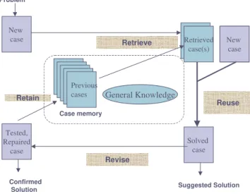
Case-Based Reasoning (CBR) is a general paradigm to Artificial Intelligence (AI) problem solving based on the recall and reuse of
specific experiences (Maher and Gomez de Silva Garza 1997). The CBR systems provide new solutions by analogy of past design situations, based on an adaptation of the previous selected solutions (Fig. 2). The main argument underlying CBR systems, is that human problem solving does not always involve reasoning from first principle, but may alternatively be a matter of relating information about a problem to past experience of solving problems (Lees 1997). This argument provides some implementation advantages of CBR systems in relation to KBS, such as not requiring an explicit domain model and identifying only significant features that describe a case (Watson and Marir 1994; Maher and Pu 1997). Also, CBR uses actual past experiences to learn and solve new problems, rather than generalised heuristics, as in knowledge-based systems/expert systems
Retrieve
Suggested Solution
Revise Retain
Retrieved case(s)
Reuse
Solved case
New case New
case Problem
Tested, Repaired
case
Confirmed Solution
Previous cases
Case memory
General Knowledge
Figure 2. Representation of the CBR technique phases.
This work discusses the use of additional information models together with a CBR approach to support the reuse of information and knowledge in the initial phases of the friction element product. The CBR approach has been chosen due to the difficulty to identify a minimum set of general rules to represent the knowledge associated to the friction material designers. The next section describes the friction material development process, stressing the main information involved in this process and the need for information model relationships. Afterwards, the structures of the information models are presented followed by the presentation of some results achieved so far. Finally, the conclusions are presented.
Brake Friction Material Development Process
Brake pads are one of the very known applications of brake friction elements in the automotive vehicles. The brake pads are usually composted by three components: backplate, adhesive, and friction material. The last one is where most effort is put in when designing a new brake pads, as it keeps most of the knowledge related to the material composition and its manufacturing process.
Three main kinds of raw material used in the final composition of the friction material are: abrasives, resin and fillers. The combination of these three raw materials along with the manufacturing process parameters must assure the technical specifications defined by the final costumer. The search for successful solutions, which attend the technical characteristics specified in the project and the cost requirements, demands cooperative multidisciplinary team, composed mainly by final costumer (OEM or suppliers), application engineers (responsible for the tests and validation), and chemical engineers (responsible for the chemical formulation and the manufacturing process) (Fig. 3).
Costumers
...
Purchase
Sales
ProjetoDesign Product ModelProduct Model
Additional Additional I & K I & K Model Model
+
+
Validation
Validation
Manufacturing
Manufacturing
Figure 3. Product development cycle of Brake Pads.
The friction material development process is based on two main activities, which are: the identification of the right chemical formulation and the definition of manufacturing process parameters. While the former one is related to the determination and
combination of the raw materials that define the final composition of the friction material, the latter one is related to the process parameters definition of each manufacturing operation. These two activities determine the final physical and mechanical properties of the friction material. During the development process several cycle of “chemical formulation” – “definition of manufacturing parameters” – “tests and validation cycles” can be realised, until the original product specifications be achieved. The chemical engineer is considered the central element of this process and is responsible for gathering the project specifications and constraints, and defining the chemical formulation and the manufacturing parameters.
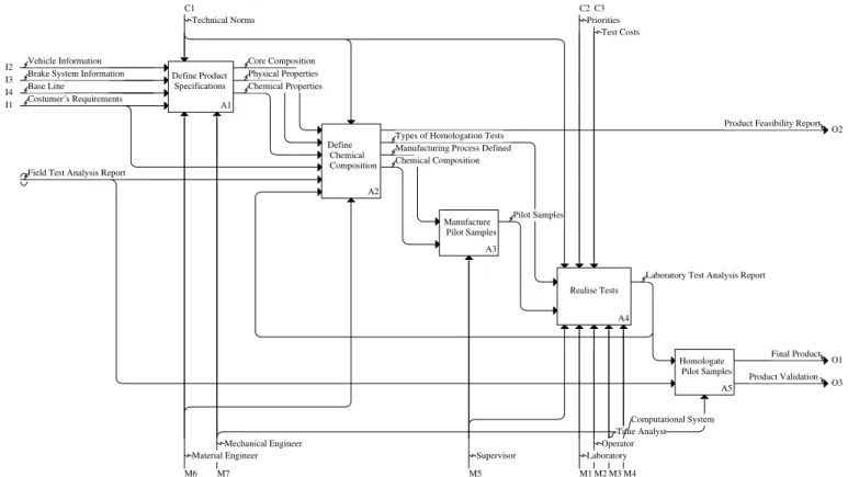
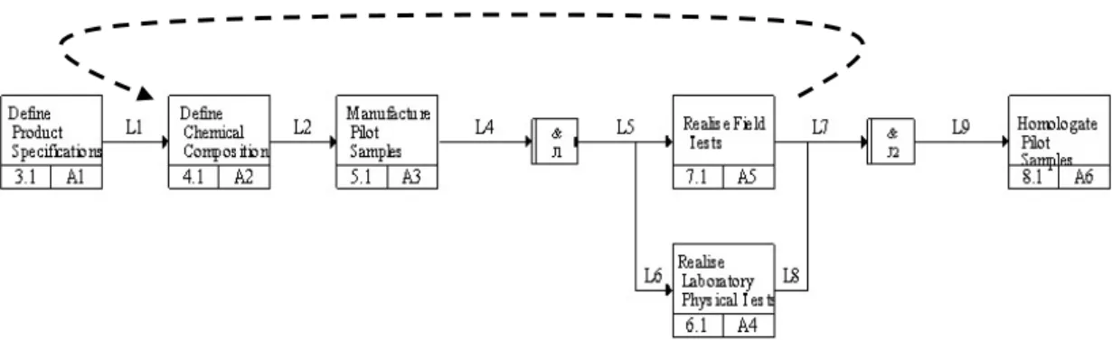
In order to provide a better understanding of the actors, information and activities, which are part of the friction material development process, functional and process models have been built by the use of IDEF0 (Integration DEFinition for Function Modelling) and IDEF3 (Process Description Capture Method Report) techniques. While the IDEF0 provided an understanding of the main activities and information that are part of the development process, the IDEF3 identified the sequence on which such activities happen.
Figure 4 depicts the main activities and the information flow identified within the friction material development process cycle, where are highlighted the activities of: Define Product Specification; Define Chemical Composition; Manufacture Pilot Samples; Realise Tests, and Homologate Pilot Sample. The sequence of activities, depicted in the IDEF3 diagram (Fig. 5), defines the product development cycle that must be repeated until the final product achieves the costumer specification.
These diagrams have helped in the definition of the main information structure classes that represent the product information model and the design information and knowledge reuse model, which are discussed in the next section.
O1
O3 O2 I4
I2 I3
C2 C3
M1 M2 M3 M4 M5
C1
M6 M7
I1
Homologate Pilot Samples
A5 Realise Tests
A4 Manufacture
Pilot Samples
A3 Define
Chemical Composition
A2 Define Product
Specifications
A1
Final Product
Product Validation Laboratory Test Analysis Report Pilot Samples
Types of Homologation Tests Manufacturing Process Defined Chemical Composition Field Test Analysis Report
Product Feasibility Report Costumer´s Requirements
Base Line
Physical Properties Chemical Properties Vehicle Information
Brake System Information
Core Composition
Priorities Test Costs
Laboratory Operator
Time Analyst Computational System
Supervisor Technical Norms
Material Engineer Mechanical Engineer
Figure 5. Process flow diagram for the development cycle of brake friction material – IDEF3.
Information Models for Friction Material
In order to define information structures that capture not only the information related to the product life cycle, but also, the information and knowledge associated to the different phases that support the product development process, this research has proposed two information models: the Brake Friction Material Model and the Friction Material Design Knowledge Model. While the first one is responsible for capturing information about the product life cycle, the latter one is in charge of capturing the information and knowledge associated to the cases in the product development process (Fig. 6).
While the approach proposed provides independence between both models structures, allowing that future changes in the structure of one model, do not affect the structure of the other one, it requires compatibility between the information structure in order to allow in information exchange between both models.
Brake Friction Material Model
Friction Material Design Knowledge Model
Case 1 Case n
Case 4
Case 3
Case 2
Figure 6. Information structures to support brake friction material I&K reuse.
Brake Friction Material Model
Although each specific brake pad friction material is chemically different from the others, they can be represented by a common information structure. An object oriented approach has been used in the definition of this information structure for the capture of information about brake friction material, i.e. Brake Friction Material Model. The Unified Modelling Language (UML) Class diagrams have been used for the representation of this model. The Class diagrams represent the internal structure of objects describing
their names, attributes and methods. In addition, such diagrams also represent the relationships between objects that are described in terms of inheritance, association or aggregation types of relationships (Booch, Rumbaugh et al. 1999).
The Brake Friction Material Model aims to capture and share information related to life cycle of a specific product that is being developed and produced for the final costumer. Figure 7 depicts the main classes that represent this model, stressing the brake pad friction element and its relationships.
In this diagram the Brake Pad Friction Element class is composed by Accessories, Application and Formulation classes. The Accessories class represents additional components that are used in the final assembly of the brake pad friction material, such as backplate, adhesive, identifying paint, shims. The Application class is related to the main use of the friction element, i.e. industrial or vehicular. Finally, the Formulation class, main focus of this work as it holds most of the required and generated I&K during the development process, has association with Geometry, Manufacturing Processes and Validation classes. This paper is mainly focused on the Manufacturing Processes class, which encompasses the raw material formulation and their manufacturing processes.
Field Test Laboratory Tests is_ass ociated_to Test_Machine Accessories Application
Brake System Homolagation Graphics
Raw Materials
Brake Pad Friction Element
1..n
1 1..n
1
1..n 1
1..n 1
Geometry
Validation
is_associated_to
1..n
1 1..n
1
has
Formulation
n 1
n 1
is_composed_by
1 1
1 1
has 1
1
1
1
has
1..n 1
1..n 1
has
Manufacturing Processes 1
n 1
n
has
has has
Figure 7. Class Diagram for the Brake Friction Material Model.
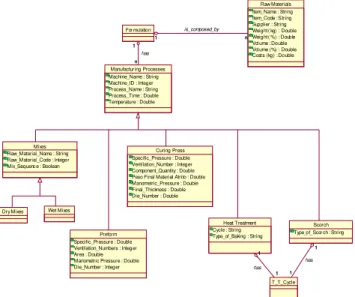
In the Mixture process the several raw materials (abrasives, resin and fillers) are mixed together based on a pre-defined sequence for adding each raw material, time and temperature. If the resin is in liquid form, then the process is termed Wet Mixes and if the resin is in powder form, is termed Dry Mixes. In the following process, i.e. Preform, this mixture is cold pressed to give the final product shape.
The following process is the Press Curing, where parameters such as time, temperature and pressure, must be critically controlled as they are responsible for the final mechanical properties of the friction material. Parameters such as Ventilation_Number mean the number of times that the press die must open to allow the run of gases generated during the process.
Mixes Raw_Material_Name : String Raw_Material_Code : Integer Mix_Sequenc e : Boolean
Curing Press Specific_Pressure : Double Ventilation_Number : Integer Component_Quantity : Double Peso Final Material Atrito : Double Manometric_Pressure : Double Final_Thickness : Double Die_Number : Double
Preform Specific_Pressure : Double Ventilation_Numbers : Integer Area : Double Manometric Pressure : Double Die_Number : Integer Dry Mixes Wet Mixes
Heat Treatment Cycle : String Type_of_Baking : String
T_T_Cycle 1 1 1 1 has Scorch Type_of_Scor ch : St ri ng
1 1 1 1 has Manufacturing Processes Machine_Name : String Machine_ID : Integer Process_Name : String Process_Time : Double Temperature : Double
For mulation 1 n 1 n has Raw Materials Item_Name : String Item_Code : String Supplier : String Weight ( kg) : Double Weight ( %) : Double Vol ume : Double Vol ume (%) : Double Cost s (kg) : Double
1 n
1 n
is_composed_by
Figure 8. UML representation of the Manufacturing Processes Class.
There are also other two manufacturing processes that are usually applied: Heat Treatment (known also as Baking) and Scorch processes. While the first one is responsible for complementing the curing of the material, the latter is required to minimise the effects of “first braking” (when brake pads are used for the first time after their change). However, as these processes do not present much I&K associated to their application, they are not focused on this paper.
During the friction material development process the formulation is applied to a “pilot sample”, manufactured in laboratory. It will be tested, physically in laboratory and in the field to check if the project specifications are achieved. If the project specifications are achieved, the friction material is considered approved and it follows the downstream life cycle activities to be produced commercially. In this situation, the information are stored in the Brake Friction Material Model.
However, if the project specifications are not achieved, a new development cycle begins, where a new formulation is defined with changes in the raw materials and/or manufacturing processes. Each new cycle is termed experiment, and it holds a set of information and knowledge related to its assumptions and results. This kind of I&K is usually not shared or integrated, and is stored in specific documents formats, which makes its reuse very difficult. Even if a experiment has been not successful for a desired project, it hold a set I&K that can be helpful as starting formulation in a new project.
This stresses the need for capturing not only life cycle product information, but also, information and knowledge built during this process of “trial and error”. The following section presents the concept and structure of the Friction Material Design Knowledge Model, which has the aim of capturing and storing the I&K created
during the development process and allows its reuse to support the development of new products.
Friction Material Design Knowledge Model
While the Brake Friction Material Model represents and captures all information associated with the product life cycle, the additional information model, i.e. Friction Material Design Knowledge Model aims to capture the I&K associated with some particular phases of the development process. In this work, the information structures of these two models are independent in spite of being interdependent in relation to the information represented. The main function of the Friction Material Design Knowledge Model is to capture cases of I&K that are part of the development (design and manufacturing) process history. Therefore, despite a minimum compatibility between classes attributes of these two models is required, their structures are different based on their specific functions.
For the Friction Material Design Knowledge Model information structure some indexes, usually applied for engineers to mental search, are being studied. These indexes must represent the way that engineers search for cases of friction materials already designed, manufactured and tested. The correct identification of these indexes helps in the definition of the more appropriate information structure for capturing and representing the cases and, in turn, the best way for searching for the information and knowledge of each case.
The indexes can vary based on the kind of activity associated to the development process cycle. The I&K reuse of a specific brake pad friction material is usually based on the final friction coefficient and its variation with temperature, pressure and wear. This kind of information is usually result of laboratory and field tests.
Figure 9 depicts a class diagram for the Friction Material Design Knowledge Model. In this figure each friction material “case” is represented by the Experiment class, which has associated the Formulation, Manufacturing Processes and Tests classes. All these classes have a relationship with Design Context class that captures the perception of the engineer for that situation, as well as the reasons for the successful or unsuccessful cases.
When a “pilot sample” is developed and tested, different results, i.e. graphics, are produced, such as friction coefficient versus wear; temperature versus wear. A critical analysis on these graphics gives to the designer an understanding to define if a particular friction material achieved or not the project specifications. This understanding stored in the Design Context class allows that part of the designer´s implicit knowledge be converted in explicit knowledge that can be reuse in future projects. The tests can be of two types: Field Tests and Laboratory Tests. The Formulation class is composed by n Raw Materials.
Field_Test s_K Test_Machine Laboratory_Tests_K Raw_Material_K Graphics_K Geometria_k Brake_System Manufacturing_Process_K Formulation_K n 1 n 1 composed_by Tests_K n 1 n 1 has is_a_kind... is_a_kind... n 1 n 1 is_associated_to Design_Context_K is_associated_to is_associated_to is_associated_to is_associated_to Experiment_K 1 1 1 1 has_a 1 1 1 1 has_a 1 1 1 1 has_a is_associated_to
Computational Implementation of a Friction Material
I&K Reuse system
Although both information models presented before can cope with the capture and representation of life cycle product information and the I&K cases, there is a need for a computational application which can support the designer in utilising both models to support one´s decisions. Figure 10 depicts the general representation of the relationships between the information models and computational application, which aid the designer in the reuse of previous I&K cases to help in one´s initial decisions of new development process.
Brake Friction Material Model
Case n
Friction Material Design Know ledge Model
Case Reuse System Supporting Brake Pad Friction Material Development Cycle
Case 1
Field Test Laboratory Testsi s_ass ociate d_toTest_Machine Accessories Application
Brake System Homolagation Graphics Raw Materials
Brake Pad Friction Element 1..n 1 1..n 1 1..n1 1..n1
Geometry
Validation is_associated_to
1..n 1 1..n 1
has Formulation n 1 n 1 is_composed_by 1
1 1 1 has 1
1 1 1
has 1..n 1 1..n 1 has
Manufacturing Processes 1
n 1
n has has has Field_T
ests_K
Test_Machine Laboratory_Tests_K Raw_Material_K
Brake_System
Graphics_K Manufacturing _Process_K Geometria_k
Formulation_K n 1 n 1 composed_by
Tests_K n 1 n 1 has
is_a_kind... is_a_kind... n 1 n 1 is_associated_to Experiment_K
1 1 1 1 has_a 1
1 1
1 has_a
1 1
1 1
has_a
Design_Context_K
is_associated_to is_associated_to is_associated_to is_associated_to
is_associated_to
Figure 10. Friction Material I&K Reuse System.
The computational implementation of the I&K reuse system is utilising an Object Oriented Database, i.e. ObjectStore®, together with the programming environment Visual C++®. While the former is being utilised to create the information structures required, the latter is aimed to implement the system functionality and interfaces with the end user. At the present, a range of Brake Pad Friction Elements has been implemented in the database to check the information models´ functionality.
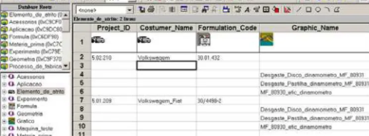
Figure 11 depicts a screen dump, where some instances of the main classes of the Brake Friction Material Model (product model) can be visualised. This visualisation is provided by the Object Inspector, which is a navigation tool for the Object Store Database. In this figure the attributes of three different objects are shown:
Project_ID and Costumer_Name from the Brake Pad Friction
Element class; Formulation_Code, from Formulation class and
finally Graphic_Name from the Graphics class, which is associated to the Validation class.
Figure 12 depicts some instances of the main classes and their attributes stored in the Friction Material Design Knowledge Model, where EXP_ID is the identification of the experiment (Experiment class); the Process is the name of the manufacturing process applied (Manufacturing Processes class), Project_ID is the project on which the experiment is being developed, Form_Code is the code of the Formulation used and, finally, Graphic is the name of the graphics generated by the tests realised. Although the last three Experiments (00534/02, 01011/02 and 01012/02) present the same Formulation Code (30/4498-2), they are different because of the manufacturing process characteristics, which can vary either, in sequence or in the process variables.
Figure 11. Example of instances of Brake Pad Friction Element, Formulation and Graphics objects.
Figure 12. Example of instances of the Friction Material Design Knowledge Model.
Conclusions
This paper has discussed how additional information models can be used to capture information and knowledge which support the designers in their initial decisions for new product development. Two information models have been presented, i.e. Brake Friction Material Model and Friction Material Design Knowledge Model. While the first one provides a unique and unambiguous information structure to support the whole life cycle functions, the latter one captures the I&K generated throughout the cycle of each development process. The general structure of the Friction Material Design Knowledge Model has been defined in terms of Experiment, Formulation, Manufacturing Processes and Tests classes.
This approach allows that each cycle of the development process can be treated as a particular case, which encompass information and knowledge related to the friction material development process, stored as a set of related object instances.
Although the information structures of these two models have been separately defined, they have been designed simultaneously as they keep a strong interdependency. Such approach can provide more independence of each model from future changes in the other one.
Acknowledgements
The authors wish to thank the Fras-Le S.A. for its support and cooperation, the Brazilian Government (CNPq - Conselho Nacional de Desenvolvimento Científico e Tecnológico), FAPERGS (Fundação de Amparo a Pesquisa do Rio Grande do Sul), and UCS (Universidade de Caxias do Sul) for the financial support.
References
Anderl, R. (1997). "Trends in Product Modelling". 11th International Conference on Engineering Design - ICED'97, Tampere - Finland, Tampere University of Technology.
Ashworth, M., Bloor, M. S., McKay, A. and Owen, J. (1996). “Adopting STEP for in-service configuration control.” Computers in Industry 31: 235-253.
Booch, G., Rumbaugh, J. and Jacobson, I. (1999). "The Unified Modeling Language User Guide". Massachusetts, Addison Wesley Longman, Inc.
Caillaud, E. and Noyes, D. (1996). "Knowledge Engineering for Design". Engineering Systems Design and Analysis Conference - Petroleum Division, ASME.
Dixon, J. R. (1995). “Knowledge-Based Systems for Design.” Transactions of the ASME 117: 11-16.
Duffy, A. H. B., Smith, J. S. and Duffy, S. M. (1998). "Design reuse research: a computational perspective". Engineering Design Conference'98 - Design Reuse, Brunel, Professional Engineering Publishing Ltd.
Finger, S. (1998). "Design reuse and design research". Engineering Design Conference'98 - Design Reuse, Brunel, Professional Engineering Publishing Ltd.
Fowler, J. E. (1996). “Variant Design for Mechanical Artifacts: A State-of-the-Art Survey.” Engineering with Computers 12: 1-15.
Gu, P. and Chan, K. (1995). “Product Modelling using STEP.” Computer-Aided Design 27(3): 163-179.
Hsu, W. and Woon, I. M. Y. (1998). “Current Research in the Conceptual Design of Mechanical Products.” Computer-Aided Design 30(5): 377-389.
Jo, H. H., Parsaei, H. R. and Sullivan, W. G. (1993). "Principles of concurrent engineering". Concurrent Engineering: Conteporary issues and modern design tools. H. R. Parsaei and W. G. Sullivan. Cambridge, Chapman & Hall: 3-23.
Kiritsis, D. (1995). “A Review of Knowledge-Based Expert Systems for Process Planning. Methods and Problems.” International Journal Advanced Manufacturing Technology 10: 240-262.
Krause, F. L., Kimura, F., Kjelberg, T. and Lu, S. C.-Y. (1993). “Product Modelling.” Annals of the CIRP 42(2): 695-705.
Lees, B. (1997). "Engineering Design Support Through Case-Based Reasoning". IEE Colloquium, London, IEE.
Lei, B., Taura, T. and Numata, J. (1996). "Representing The Collaborative Design Process: A Product Model-Oriented Approach". Advances in Formal Design Methods for CAD. J. S. Gero and F. Sudweeks. London, Chapman & Hall: 267-285.
Maher, M. L. and Gomez de Silva Garza, A. (1997). “Case-Based Reasoning in Design.” IEEE Expert(March-Abril): 34-41.
Maher, M. L. and Pu, P. (1997). "Introduction to the Issues and Applications of Case-Based Reasoning in Design". Issues and Applications of Case-Based Reasoning in Design. M. L. Maher and P. Pu. New Jersey, Lawrence Erlbaum Associates, Publishers: 1-9.
McKay, A., Bloor, M. S. and De Pennington, A. (1996). “A Framework for Product Data.” IEEE Transactions on Knowledge and Data Engineering 8(5): 825-837.
Sivaloganathan, S. and Shahin, T. M. M., Eds. (1998). "Engineering Design Conference'98 - Design Reuse". London, Professional Engineering Publishing Ltd.
Sivaloganathan, S. and Shahin, T. M. M. (1999). “Design reuse: on overview.” Proc. Instn. Mech. Engrs, Part B, Journal of Engineering Manufacture 213: 641-654.
Tichem, M. and Storm, T. (1997). “Designer support for product structuring-development of a DFX tool within the design coordination framework.” Computer in Industry 33: 155-163.
Tonshoff, H. K. and Zwick, M. (1998). "An Integrated Product and Process Model". Proceedings of the Tenth International IFIP WG 5.2/5.3 Conference PROLAMAT 98. G. Jacucci, G. J. Olling, K. Preiss and M. Wozny. Trento, Kluwer Academic Publishers.
Venkatachalam, A. R., Mellichamp, J. M. and Miller, D. M. (1993). "Automating design for manufacturability through expert systems approaches". Concurrent Engineering - Contemporary Issues and Modern Design Tools. H. R. Parsaei and W. G. Sullivan. Cambridge, Chapman & Hall: 426-446.
Watson, I. and Marir, F. (1994). “Case-Based reasoning: A review.” The Knowledge Engineering Review 9(4): 327-354.
Yoshioka, M., Sekiya, T. and Tomiyama, T. (1998). "Design Knowledge Collection by Modelling". Proceedings of the Tenth International IFIP WG 5.2/5.3 Conference PROLAMAT 98, Trento, Kluwer Academic Publishers.