Design and prototyping of Haptic Surfaces
Rui Adriano Gomes Correia Pinto
Dissertation
Supervisor: Paulo Abreu
Co-Supervisors: Teresa Restivo, João Carneiro
Master’s in Mechanical Engineering
Abstract
Haptic devices are used to interact with Virtual Environments. Haptic Surfaces are haptic devices that allow the user to explore, by touch, the proprieties of the surface that can be actively controlled, such as mechanical proprieties like stiffness or even its entire shape.
This thesis explores the design and development of Haptic Surfaces that allow for an adjustable stiffness through a method of particle compression known as particle jamming. This method typically compresses particles of a granular material through a pneumatic system, responsible for the manipulation of vacuum pressure. The stiffness of the surface is controlled by adjusting the level of applied vacuum pressure.
Several preliminary prototypes were developed and characterized by experimental evaluation. The relation between applied vacuum and the stiffness exhibited by the surface was experimentally determined. As a result, two distinct variable stiffness Haptic Surfaces for hand rehabilitation/training application were developed using off-the-shelf components.
The Haptic Surfaces were explored as a hand rehabilitation device integrated in a software application. The main advantage of the surfaces in this context is the ability to adjust the stiffness the device offers to different hand/finger exercises. This allows for an individualized train in accordance with the user’s needs. Additionally, the application provides visual information to the user by representing surface’s stiffness through a virtual model.
Conceção de Superfícies Hápticas como elemento de feedback em
ambientes virtuais
Resumo
Os dispositivos hápticos são utilizados para interação com ambientes virtuais. As Superfícies Hápticas são dispositivos hápticos onde o utilizador explora, através do sentido do toque, propriedades da superfície que podem controladas ativamente, como, por exemplo, a sua rigidez ou a forma.
Este trabalho explora a conceção e design de Superfícies Hápticas que permitem o controlo da rigidez através de um método de compactação de partículas conhecido como “particle jamming”. Neste método a compactação de partículas granulares é, tipicamente, assegurada por um sistema pneumático de controlo de vácuo. A rigidez da superfície é controlada pelo nível de pressão de vácuo imposto.
Foram desenvolvidos e experimentalmente caracterizados vários protótipos preliminares. A relação entre a pressão de vácuo imposta e a rigidez apresentada pelas superfícies foi experimentalmente determinada. Como resultado das avaliações experimentais, foram consideradas duas distintas Superfícies Hápticas para integração em aplicações de reabilitação/treino da mão. A aplicação de software desenvolvida neste contexto tira partido da possibilidade de ajustar a rigidez da superfície permitindo a realização de exercícios com graus de exigência distintos. Isto permite individualizar o treino de acordo com as necessidades do paciente. Adicionalmente, a aplicação disponibiliza informação visual, ao representar a rigidez das superfícies através de um modelo virtual.
Agradecimentos
Gostaria de agradecer aos meus orientadores, Prof. Paulo Augusto Ferreira de Abreu, Prof. Maria Teresa Restivo e Prof. João Pedro Falcão Carneiro por possibilitarem e apoiarem a realização deste projeto.
Gostaria de agradecer também aos Professores da FEUP: Renato Natal e Torres Marques pelo apoio prestado durante a realização deste trabalho. Na mesma nota, agradeço também ao funcionário da faculdade: Sr. Ramalho, aos membros do INEGI: Eng. Pedro Martins e D. Júlia Meira, ao Eng. Vitalino e ao fisioterapeuta Jorge Antunes pelo apoio prestado no desenvolvimento do projeto.
Gostaria ainda de agradeçer a todos os meus amigos e colegas pelo apoio prestado ao longo do mestrado e a todos aqueles que me ajudaram a concluir o curso.
Por último, agradeço aos meus pais e familiares por possibilitarem e apoiarem o meu percurso académico desde o início.
Contents
1 Introduction ... 1
1.1 Problem Identification ... 1
1.2 Project Objectives ... 3
1.3 Dissertation’s Structure ... 3
2 Haptic Surfaces Overview ... 4
2.1 Illuminating Clay and Sandscape ... 4
2.2 Digital Clay ... 5
2.3 Applications for table-tops, tablets and portable shape-changing mobile-devices ... 6
2.4 Vacu-Sl... 7
3 Particle Jamming method ... 9
3.1 Jamming Principles ... 9
3.2 Jamming Applications ... 11
3.3 Materials and Control Solutions ... 11
3.4 Experimental tests ... 13
4. Design and characterization of Haptic Surfaces ... 17
4.1 Surface Design ... 17
4.2 Control Solutions ... 21
4.3 Experimental Tests ... 23
5 Haptic Surface as a Hand Rehabilitation/Training Tool ... 35
5.1 Hand Rehabilitation/Training ... 35
5.2 Haptic Surfaces for Hand Rehabilitation/Training ... 37
5.3 Software Application ... 38
6. Conclusions and Future Work ... 41
Acronyms
ADL – Activities of Daily Living DOF – Degree of Freedom
FEUP – Faculty of Engineering of the University of Porto
INEGI – Institute of Science and Innovation in Mechanical and Industrial Engineering
LIM – Laboratory of Instrumentation for Measurement MVC – Maximum voluntary contraction
OA – Osteoarthritis
VAC – Vacuum Assisted Closure
VE – Virtual Environment VR – Virtual Reality
List of Figures
Figure 1 – Haptic surface communication with the user ... 2
Figure 2 - Illuminating Clay [9] ... 4
Figure 3 - Visual interface for Bed of Nails (a) and Formable Crust device (b) [10] ... 5
Figure 4 - Four examples of Haptic devices based on particle jamming [8] ... 6
Figure 5 - Haptic Jamming Tactile Display prototype [7] ... 7
Figure 6 - Vacu-Sl’s working principle [13] ... 7
Figure 7 - Illustrations of particle interactions: Intrusion (a) and Hopping (b) [13] ... 10
Figure 8 - Jamming Skin Enabled Locomotion prototype [18] ... 11
Figure 9 - Control solution for a Jamming User Interface [8] ... 13
Figure 10 - Graphic of the evolution of stiffness with vacuum [18] ... 14
Figure 11 - Stress vs Strain curves for different levels of vacuum pressure [18] ... 14
Figure 12 - Experimental test set-up using the Phantom Premium haptic device [20] ... 15
Figure 13 - Force/stress vs displacement/strain curves for coffee grounds [20] ... 15
Figure 14 - Detail of the sealant applied to earlier prototypes of surface A ... 18
Figure 15 - Test for leaks on an early surface A prototype (a) and detected air leaks (b) ... 19
Figure 16 - Final iteration for type A Haptic Surface prototype ... 19
Figure 17 - Surface B iterations based on: silicone air pump (a) and silicone bottle ... 20
Figure 19 - Pneumatic system for digital control of vacuum pressure ... 22
Figure 18 - Fixed control solution for the Haptic Surface ... 22
Figure 20 - Portable control solution based on a small vacuum pump... 23
Figure 21 - Surface A filled with coffee supported by a box during the test ... 24
Figure 22 - 3D designed (a) and printed (b) support for surface B indentation tests ... 25
Figure 23 - System used for the indentation tests ... 25
Figure 24 - Time distributions of Force and Displacement, for surface A prototype with sand, at atmospheric pressure ... 26
Figure 25 - Testing location for surface B in the frontal area (a), and side area (b) ... 27
Figure 26 - Evolution of S variable, with vacuum pressure, for surfaces A ... 28
Figure 27 - Evolution of S variable, with vacuum pressure, for surfaces B ... 29
Figure 28 - Force displacement curves for a type A surface filled with decorative sand ... 30
Figure 29 - Force deflection curves for surface B prototypes with "couscous". ... 32
Figure 30 - Force deflection curves for a point in the side region of surface B with "couscous" ... 33
Figure 31 - Comparison between stiffness in the "front" and "side" region of surface B ... 33
xiv
Figure 33 - Illustration of finger movements: extension/flexion and adduction/abduction [27]
... 36
Figure 34 - Digi-flex device demonstrating two ways of handling it [28] ... 37
Figure 36 - Application’s interface for the Haptic Surface developed ... 38
xvi
List of Tables
Table 1 - Brief overview of six Haptic Surfaces examples ... 8
Table 2 - Typical experimental evaluations to characterize a jamming surface ... 16
Table 3 - Proprieties of the selected haptic surfaces ... 21
Table 4 - Indentation tests performed ... 27
Design and prototyping of Haptic Surfaces
1 Introduction
This dissertation explores the design and control of Haptic Surfaces, giving continuity to previous work developed at the Faculty of Engineering of the University of Porto, in the Laboratory of Instrumentation for Measurement (LIM), within the framework of haptic devices. Namely, this work was inspired by two previous developments. The first one was a “do-it-yourself”, one degree of freedom (DOF) haptic device. It is a force feedback device with one linear degree of freedom and is being used in several available virtual experiments within FEUP’s online experimentation resources [1]. The second one was a therapy device oriented to hand functionality training [2]. The device used the method of particle jamming. This present dissertation aims to further explore particle jamming to control stiffness, by evaluating surfaces with different compositions, and verifying its applicability in hand rehabilitation/training.
1.1 Problem Identification
The word Haptic derives from the Greek: hapto - to touch [3], [4]. The sense of touch is not localized to a specific region of the body like the other four senses (sight, hearing, taste and smell) [5], instead it is distributed across the human body through the touch sensory organ, skin, joints, muscles and tendons. This sense can be divided in two modalities; kinaesthetic and tactile, where kinaesthetic sensations (forces and torque) are sensed in the muscles, joints and tendons and tactile sensations (pressure, shear stress and vibrations) are sensed by mechanoreceptors, which are touch sensory organs present in the skin [5].
The bidirectional nature of touch is considered the most prominent feature of Haptic interaction [3] as it intrinsically enables the exchange of information. Haptic technology takes advantage of this property and establishes a communication between the human user and the Virtual Environment (VE). A haptic devices communication does not have to be done exclusively by the sense of touch as it can also be supplemented by the visual and auditory senses, improving communication efficiency [4]. A Virtual Environment can be defined as “a computer-generated display that allows or compels the user (or users) to have a sense of being present in an environment other than the one they are actually in, and to interact with that environment” [6].
For the purpose of this dissertation, Haptics is defined as the field of study concerned with an interaction, between the user and a Virtual Environment, utilizing the sensation of touch as a mean of transferring information and subsequently establishing communication.
Design and prototyping of Haptic Surfaces
2
Haptic devices can be divided in three categories: those that require the user to hold and handle a mechanism (graspable), those that the user wears (wearable) and those that are touched by the user (touchable). This last type of devices includes Haptic Surfaces that allow the user to explore, with the sense of touch, surface proprieties that can be actively controlled, such as stiffness or texture. In this way, it is possible to implement haptic feedback solutions for software applications concerned with the handling and visual representation of objects or products.
In the context of this dissertation, Haptic Surface will be defined as a touchable device with a tactile display where there is a communication via kinesthetics and or tactile sensations between the user and the software application.
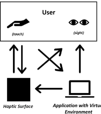
An outline of a Haptic Surface’s communication with the user is presented in Figure 1. The diagram presents a Haptic Surface, whose stiffness can be adjusted without sensing components, meaning it cannot detect deformations caused by the user. Figure 1 illustrates how both the user and the software application with a VE interact with the physical surface: the user interacts with the application to select a stiffness value for the surface. This stiffness is then imposed to the physical surface and can be felt by the user, via the sense of touch (haptic feedback). The deformations caused by user interaction can be seen in the physical model, and surface stiffness can be estimated by visual inspection of this device. Additionally, the surface is presented in the application, providing a complementary visual information on the selected stiffness. This representation is particularly relevant, for example, in rehabilitation or training applications.
Figure 1 – Haptic surface communication with the user
User
Application with Virtual Environment
Design and prototyping of Haptic Surfaces
It is also possible to consider closed loop control for the presented system, by adding sensing components to measure the deformations made on the surface by the user [7]. This can be done by measuring the applied force (force sensing) [7], or by measuring the surface’s displacement (optical sensing) [8].
1.2 Project Objectives
This dissertation aims to explore the use of pneumatic systems to achieve particle jamming as a mean to control surface’s stiffness and shape. In this technique loose particles present in granular matter are compressed using vacuum, converting the material’s previous liquid-like behaviour into a rigid-like one.
It is known that different levels of particle tightness (different levels of applied vacuum) will match different types of rigid behaviour; a material where the particles are compressed together will display a stiffer surface. As such, a study is conducted to determine the range of adjustable stiffness for different granular material, under distinct vacuum pressures.
The objectives of this study can be divided into three main points:
1. Design and development of Haptic Surfaces preliminary prototypes based on particle jamming;
2. Characterization of those surfaces via experimental evaluation;
3. Development of an application to be used with those surfaces within the framework of hand rehabilitation/training.
1.3 Dissertation’s Structure
Having provided a brief context of the project in this Chapter, chapter 2 discusses several examples of existing Haptic Surfaces, some of which implement the method of particle jamming to modify surface’s stiffness. Chapter 3 describes the theory behind this method and gives an overview of materials, control solutions and typical experimental tests performed to characterize these surfaces. Chapter 4 details the design and development of two Haptic Surface prototypes, including materials, control solutions and experimental evaluations implemented. Chapter 5 describes a software application with a VE for the Haptic Surfaces in the context of hand rehabilitation/training devices. In Chapter 6 conclusions and future works are presented.
Design and prototyping of Haptic Surfaces
4
2 Haptic Surfaces Overview
2.1 Illuminating Clay and Sandscape
Two Haptic Surfaces with the same working principle but different sensing technology are presented in [9]. In these devices the surface is either made of clay (Illuminating Clay) or sand (Sandscape). The surface can be digitally augmented by the projection of guiding lights and its deformation can be detected by optical sensors. The user interacts with the surface through haptic stimuli. The interaction is then captured in real time, by either a triangulation-based scanner (Illuminating Clay) or a system employing infrared technology (Sandscape) and displayed in a digital model of a VE. Changes made in the physical surface are captured and presented in the VE, while changes made in the digital model are presented in the surface by a series of lights. The VE provides the user with a library of landscape analysis to implement these changes. Figure 2 presents the Illuminating Clay device.
The prototypes Illuminating Clay and Sandscape [9] were built specifically for applications in the domain of landscape architecture; however, the concept could be translated into other fields like contemporary architecture or automobile design. These devices proved efficient in combining physical and digital representations for landscape modelling and analysis. They show a series of advantages to existing non haptic landscape analysis apparatus: real-time feedback, simplified handling, clearer vision of the landscape and the ability to immediately preview results of a new sculpted surface.
Design and prototyping of Haptic Surfaces
The negative aspects are related either to the high cost (triangulation-based scanner) or to material selection (Sandscape); the Sandscape project requires a specific type of granular material for the correct reflection of the infrared rays and therefore the correct functioning of the surface.
It is important to note that in this type of systems, the software application cannot change the physical proprieties of the physical model; instead it provides a reliable representation of the surface inviting the user to interact with it.
2.2 Digital Clay
The goal of the project described in [10] was the design and prototyping of a controlled physical device able to take a wide range of shapes as a response to changes in a digital 3D model [10]. It was also meant to allow two remotely located users to simultaneously sculpt the same object, by sharing a virtual 3D model between them.
The project offers solutions for different areas of applications, among which: Computer Aided Design (CAD), architecture, art, medical training and assistance to the visually impaired. Two prototypes were made to achieve the mentioned goals: the “Bed-of-Nails” and the “Formable-Crust”. Both prototypes can be considered graspable device as the user is required to hold and manipulate an additional mechanism in order to control the surface’s shape.
The first prototype is composed by a matrix of linear hydraulic actuators, with integrated linear sensors, arranged on a two-dimensional grid. A non-specified material covers the top to simulate skin, as presented in Figure 3 (a). Each actuator defines the height of a vertical piston enabling the surface to assume a series of shapes; although limiting, the fact that only one axis is controlled also translates into a simplified hardware-software programming. The second prototype, illustrated in Figure 3 (b), is based on a mechanical structure powered by inflatable chambers, developed by Dr. Ebert-Uphoff and Paul Bosscher [10].
Design and prototyping of Haptic Surfaces
6
2.3 Applications for table-tops, tablets and portable shape-changing mobile-devices
The design of four Haptic Surfaces prototypes based on particle jamming are reported in [8]. The goal was to investigate the potential of variable material stiffness for different user interfaces: Tuneable Clay, Transparent Haptic Lens, Behind-the-Tablet Jamming and ShapePhone (presented in Figure 4).
The Tuneable Clay was inspired by Illuminating Clay/Sandscape [9] and provides a surface that works as a malleable input for 3D modelling. Deformations caused by user interaction are registered in real time in a 3D model. The user can also, manually, adjust the stiffness of the physical surface to assist in the sculpting process. Adjustable stiffness is achieved by using the method of particle jamming. This device achieves particle jamming through an oil based hydraulic system and using Pyrex glass beads as the jammable material. Additionally, optical sensing is achieved by using structured light through the back of the transparent jamming volume, capturing the shape in real-time.
The Transparent Haptic Lens also uses an oil based hydraulic system and Pyrex glass beads to achieve particle jamming and consists of a round metal ring with a transparent base and a transparent silicone upper skin, for user interaction. The device is tracked in a tangible table-top display, it uses varying stiffness as a haptic information channel by allowing the user to feel the stiffness of parts of images, displayed in a tangible table-top display, when moving the device and pressing into the “lens”.
For the behind-the-tablet jamming, a jamming apparatus, including capacitive shape-sensing of the surface, is mounted in a tablet case and placed behind a tablet. The user interacts with applications in the tablet by pressing into the back of the device. This device utilizes a pneumatic system to achieve particle jamming, with coffee grounds as the jammable matter, and capacitive sensing to detect deformations. The ShapePhone uses the same particle jamming set-up and is a phone-size portable device that can be stretched and moulded into a variety of shapes. The shapes are formed by locking the moulded surface by stiffening the surface, maintaining the selected shape.
There are several other articles detailing other Haptic Surfaces [7], [11], [12], capable of changing geometry and stiffness through pneumatic power and particle jamming. These systems are named “Haptic Jamming Tactile displays” and aim to replicate a virtual shape by independently altering the stiffness of a series of nodes displayed in a matrix structure. One of these systems can be observed in Figure 5.
Design and prototyping of Haptic Surfaces
2.4 Vacu-Sl
Vacu-Sl [13] is a Haptic Surface designed to support the full functionalities of flexible endoscopes used in medical surgery. For these medical procedures it is desirable to have a shaft-guide that is flexible when entering the human body and rigid when properly positioned to support the flexible endoscope. The conceived device, presented in Figure 6, consists of a foil tube, filled with particles, that is rigidified by applying vacuum inside it. A study was made to find the relations between the filler particles size, shape and hardness and the rigidified Vacu-SL’s bending stiffness. This study tested polystyrene, acrylic glass, glass, steel, and corundum particles as spheres, pebbles and granulate with average diameters between 0.16 and 0.17 mm.
Figure 6 - Vacu-Sl’s working principle [13] Figure 5 - Haptic Jamming Tactile Display prototype [7]
Design and prototyping of Haptic Surfaces
8
To conclude this chapter, the current developments on Haptic Surfaces mentioned are summarized in Table 1.
Table 1 - Brief overview of six Haptic Surfaces examples
Haptic Surfaces “Interactive” Material
Actuators Sensing Possible
application
Illuminating Clay Clay Light Optical sensing
(laser scanner)
Sculpting/Design
Sandscape Sand Light Optical sensing
(Infra-red light)
Bed-of-Nails (Digital Clay)
// Hydraulic jamming Pressure sensing (integrated in the hydraulic actuators) Behind-the-Tablet Jamming Coffee grounds Pneumatic (jamming) Capacitive shape sensing Augmented feedback
Tactile Displays No sensing. Palpation training
for medical simulators
Vacu-Sl Glass beads No sensing Medical operations
(using endoscope)
Most haptic devices allow for the control of, at least, one mechanical property, such as: stiffness, via particle jamming for example, or texture, via vibrations [5]. The solutions developed in this dissertation, presented in Chapter 4, are of Haptic Surfaces that use particle jamming and granular material to achieve variable stiffness. As such, the next chapter will be dedicated to the concept of particle jamming, used materials and experimental characterization tests that are usually performed.
Design and prototyping of Haptic Surfaces
3 Particle Jamming method
Particle jamming is present in the context of Soft Robotics to give robots bioinspired capacities that allow adaptive interactions with unpredictable environments [14]. Soft Robotics solutions are typically made of soft materials to emulate the animal world, contrasting with the generally rigid-body design of Human-made robots. Incorporating soft techniques translates to potentially less mechanical and algorithmic complexity in robot design.
Soft Robotics is a relevant topic for this dissertation since one of the main concerns of this field is stiffness modulation. Soft systems require controllable stiffness to apply forces needed to achieve a specific task. For example, for a device to grip an object, its material has to be conformable in an initial moment of contact, and rigid in a second moment, to hold the object.
Particle jamming can be found in a robotic gripper based on the jamming of granular material [15]. This is a Soft Robotics system for gripping and manipulating objects by applying vacuum inside a silicone enclosure containing granular material (coffee grounds). When vacuum is applied jamming occurs and the gripper turns into a stiff surface capable of supporting object.
3.1 Jamming Principles
Jamming represents a scenario where the behaviour of a given material transitions between liquid and rigid-like with a minimal change in volume. This is a reversible transition, caused by compressing the material’s particles, which allows for the manipulation of stiffness through the control of a jamming level.
The jamming level is dependent on the selected material and represents how tightly packed the particles are. This level ranges from a non-jammed state where the material is highly deformable, to a completely jammed state where it acts as a rigid body and its yield stress is at a maximum. The yield stress is the maximum stress that the material can withstand in the linear elastic regime. The material used for jamming is usually of a granular type, although some open-cell foams also provide similar effects [16],[17]. To achieve particle jamming through a pneumatic system, the granular matter is usually confined in a tight isolated enclosure and submitted to an adjustable vacuum pressure.
Design and prototyping of Haptic Surfaces
10
When submitted to vacuum pressure, air between particles will flow from the enclosure to the surroundings, leaving the spaces between particles and compressing them. This phenomenon is responsible for the creation of chains of particles that enable a rigid-like behaviour. When working with granular material it is useful to know how it behaves on a particle level when submitted to a disturbing force. Two major particle interaction mechanisms are responsible for the deformation of the filler volume as a whole: particle rearrangements and particle deformations [13].
Particle rearrangement describes a situation where the particles change orientation and position within a pack of particles. On a particle level, these rearrangements can be caused by a particle being pushed in between neighbouring layer particles (particle intrusion) or pushed over particles of an underlying layer (particle hopping). Both interactions are presented in Figure 7. Particle intrusion will depend on contact angle (presented above), disturbing force and friction between particles; for irregularly shaped particles, the amount of small contact angles restrains the intrusion. For particle hopping, the disturbing force acting on a particle must be sufficiently large to be able to push it over an underlying particle, it should also be horizontal or upwards as not to intrude the underlying layer. In granular material, particle hopping translates to a shear-like behaviour, since multiple particles or even an entire layer can move over an underlying layer at the same time. It was concluded [13] that a larger force is required to cause particle hopping for irregular particles when compared with round particles.
As for particle deformation, this phenomenon can either promote or inhibit the total deformation of the filler material. Due to compression, the stack height of particles is decreased, causing deformation of the surface, however, compression also deforms particles, converting them from circular shapes to hexagon or polygon type shapes. These new shapes are more stable to deformations than the previous; as mentioned before intrusion is harder for irregularly shaped particles due to their small contact angles.
This dissertation focuses on pneumatic jamming; however, it is worth noting that jamming can be achieved by a hydraulic system in a method known as hydraulic jamming [11]. In this case, instead of air, liquids are used as the interstitial fluid between particles and the same working principle applies. This method grants higher efficiency by being faster than the pneumatic approach when changing levels, it is also quieter and allows for a higher surface stiffness. However, in the hydraulic approach the pressures used for jamming are greatly lower than pressures used for most hydraulic applications, resulting in the use of less adequate components for a hydraulic jamming system. Also, for portable applications the pneumatic solution is more convenient since compressed air is more readily available than the required liquid.
Design and prototyping of Haptic Surfaces
3.2 Jamming Applications
Particle jamming is present in different applications. Some were introduced in the previous chapter like the shaft-guide for flexible endoscopes, the transparent haptic lens or the robotic gripper based on the jamming of granular material. Additionally, haptic jamming devices like the tactile displays [7],[11],[12], mentioned in Chapter 2, can be used as an interface for medical training by simulating different types of tissue covering some anatomical features detected in palpation tasks.
In [18], the use of Jamming as a mobility mechanism is reported. The goal of that study was the design and prototyping of a soft robot capable of traversing rough terrain and navigating into small holes. To achieve jamming locomotion, the prototype, presented in Figure 8, is a spherical-like volume of a non-specified fluid enclosed by an outer layer of cellular compartments filled with granular material. When the actuator expands the liquid is forced against the walls and, by selecting the cellular compartments that are stiff, or soft, the direction of this expansion can be controlled, and locomotion is achieved.
As mentioned before, jamming can also be applied to open-cell foams. One article on the subject [19] describes a medical application where vacuum is applied to a polyurethane soft sponge. This application, named vacuum assisted closure (VAC), is used as a temporary wound dressing in open fracture scenarios. In this technique, the foam is cut to fit the wound and placed into the cavity, a plastic film is applied over the foam to create an airtight seal and vacuum is applied through a hole cut in the film. The foam, at ambient pressure, is placed in the open wound and vacuum is then applied to, artificially, close the wound and avoid air exposure.
3.3 Materials and Control Solutions
As pointed out in an article on haptic jamming user interfaces [8], to control a pneumatic jamming system three main components are required:
1. Materials: jammable material and container; 2. Vacuum generator;
3. Control system: including pressure sensors and regulator valves.
This topic will be divided into two parts; the first one details materials used in previously presented Haptic Surfaces, while the second one will discuss the control solutions to achieve jamming in those surfaces.
Design and prototyping of Haptic Surfaces
12
i. Materials
The material used in most jamming applications is a granular material, such as coffee or tiny glass beads, although open-cell foams have also been used in some cases. The granular material is typically contained inside a hollow silicone shell, custom made to fit the application.
For the haptic tactile display [7], presented in Figure 5, the surface consists of two layers of silicone (Ecoflex 30, Smooth-On Inc.) cured in custom moulds and glued together, forming a 38 mm square shell. In general, the shell is required to be non-porous to keep the surface airtight. It should also provide a thin membrane surface with minimum influence on the perception of surface stiffness. Finally, it should be flexible to adapt to shape changes of the granular matter. For example, the universal robot gripper based on jamming [15] utilizes a rubber bag with 0.3 mm thickness to contain the coffee grounds.
Examples of materials used for jamming applications are: coffee grounds [7], [8], [14],[15],[20] (usually of medium coarseness) due to their large dynamic range in stiffness, and glass beads [8],[13], more commonly with a diameter of 100 µm [18], as they allow for a more precise control over the available stiffness range.
ii. Control Solutions
Regarding the control system, it requires a vacuum source, pressure control valves and pressure sensors to achieve pneumatic jamming with controllable levels. For the jamming applications mentioned throughout this work, vacuum pressures range from 0 to 0.85 bar.
Vacuum can be obtained using a vacuum pump, or by connecting a venturi valve to a compressed air source. Considering the concept of Haptic Surface established in chapter 1, the pneumatic jamming system must interact with a software application in a VE. As such, a connection must be established between the hardware and software used, through an adequate controller. Valves used to achieve variable pressure should be connected directly or indirectly to the controller.
Pressure control can be obtained with different and varied configurations. For some cases, the vacuum generator already has the functionality of adjusting output vacuum pressure and pressure control is assured. When it does not, the use of a pressure regulator after the vacuum source is the most straightforward way to achieve this.
Another alternative is to use a bypass valve that opens, in a controlled way, the passage of air from the enclosure of granular material to the atmosphere, thereby decreasing vacuum pressure. Another solution [1] describes the use of fixed pressure sources that connect to the vacuum generators using solenoid valves. In this way, discrete values of vacuum pressure can be achieved. The work [1] describes a solution able to provide three levels of vacuum pressure to the enclosure (0, 0.12 and 0.80 bar) that guaranteed three levels for surface’s stiffness: “Flexible”, “Semi-Rigid” and “Rigid”.
Design and prototyping of Haptic Surfaces
Another configuration worth noting can be found in an article describing jamming user interfaces [8]. This pneumatic system uses a microcontroller, 12V DC vacuum pump with 20 cm3/s maximum flow rate and a maximum vacuum pressure of 0.65 bar, two 12V DC solenoid
valves, a pressure sensor and an air compressor. This system is presented in Figure 9. The control of the surface’s stiffness is done by measuring and controlling its pressure with a compressor and vacuum pump directly connected, through two independently controlled solenoid valves.
3.4 Experimental tests
Several methods for experimental evaluating particle jamming surfaces were found [13],[14],[15],[18],[20]. These evaluations typically aim to explore how the surface’s stiffness behaves with vacuum pressure for a given material. Several articles report to have conducted tests for different sizes and types of granular matter, usually with particle diameters not exceeding 1.0mm [18] and vacuum pressure in the range of 0 to 0.90 bar.
Stiffness refers to the mechanical behaviour response of an object relating the deformation it presents when subjected to a given force [21]. According to this definition, different modes to characterize stiffness can be determined depending on the type of: functional force, for example, an axial force or a torque can be used to achieve deformation, and deformation measured, it can be, for example, linear displacement or angle. It is usual to conduct either a tensile test [13], that returns a stress vs strain curve, or an indentation test where a controlled force is applied to a surface and the displacement is measured [20].
The article [18] refers the use of jamming for robot locomotion and reports experimental evaluation of stiffness with vacuum level based on stress-strain curves for different types of granular material. To test different materials and particle sizes, thin flexible plastic cylindrical beams filled with several types of granular material, fully supported with their weight as a distributed load, were submitted to a controlled concentrated force applied downward in the middle of the beam with a non-specified Instron testing machine. The materials tested included glass spheres, aluminium oxide, table salt and ground corn cob. The stress vs strain curves for six levels of vacuum, for 100μm glass spheres, were discussed in the article. The beams were tested to a predetermined amount of strain (6.9%) that corresponds to the maximum strain of the weakest beam, deflected without vacuum – unjammed state.
Design and prototyping of Haptic Surfaces
14
Additionally, the article also presents a graphic that maps the evolution of an “Effective flexural modulus” with vacuum pressure for different materials. Both graphics are respectively presented in Figures 10 and 11. The flexural modulus, calculated with the stress vs strain data, represents a measure of surface’s stiffness and is a characteristic property for elastic material behaviour. In this article the modulus calculated is considered “effective” since the material does not behave strictly elastically and therefore it only represents an approximation.
The article concluded that, although these graphics provide a good description of stiffness distribution with vacuum level, in the jammed state, they do not describe the liquid like behaviour in the unjammed state. The article proposes that this characteristic is highly influenced by the angle of repose, which is the angle that a conical pile of granular material makes with the horizontal. To measure the angle, the granular matter was drained from a cylinder and the angle measured from the slope of the remaining in the cylinder. Table Salt presented the highest flexural modulus in the jammed state, making it the stiffer tested material. However, when considering the angle of repose, the glass spheres proved to be the most desirable for the article’s application (robot capable of traversing through small holes) as they grant high flexibility for the unjammed state and offer a good level of stiffness for the jammed state when compared with other materials tested.
Conversion to bar: 0 0.16 0.33 0.50 0.67 0.74
Figure 11 - Stress vs Strain curves for different levels of vacuum pressure [18] Figure 10 - Graphic of the evolution of stiffness with vacuum [18]
Design and prototyping of Haptic Surfaces
To test the tactile displays made of coffee grounds enclosed in a silicone membrane, the authors of study [20], used a configuration where a 6 axis ATI Nano 17 force/torque sensor was attached to the end effector of a 6 DOF Haptic device with force feedback (Phantom Premium, Sensable Technologies Inc.) and then manually pressed against the surface. The phantom device provides data on the exact location of the sensor, therefore, force made on the membrane and the corresponding surface’s displacement can be recorded using this set-up, illustrated in Figure 12.
To conduct these experiments, individual circular silicone cells filled with coffee particles were tested. Force vs Displacement curves for different levels of vacuum as can be seen in Figure 13. The study concluded that a nonlinear evolution of stiffness with vacuum was observed and that the curves presented high hysteresis, which was attributed to the tendency of coffee grounds to maintain shape unless disturbed by an external force [20].
It is worth noting that, in the experimental evaluations performed in [20], the silicone container filled with coffee grounds is clamped over an air chamber that can be pressurized to obtain a wider range of surface’s shapes. As such, the displacements measured in force deflection trials for this device will be much higher than those registered for devices with a rigid and fixed base, without an air chamber below the surface.
Figure 12 - Experimental test set-up using the Phantom Premium haptic device [20]
Design and prototyping of Haptic Surfaces
16
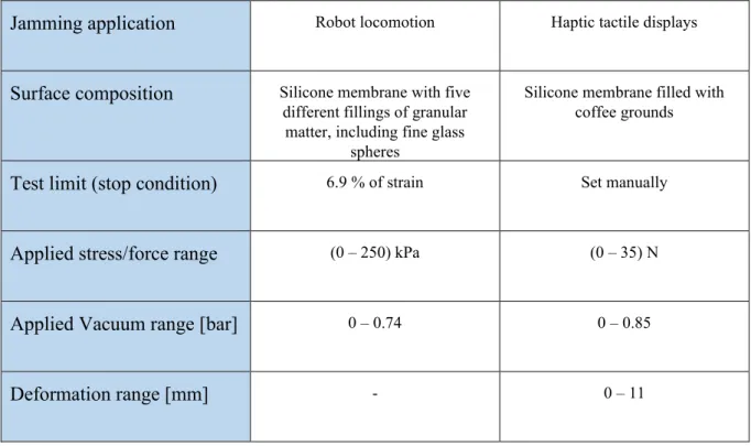
To summarize and compare the two mentioned trials, Table 2 presents the main characteristics for both experimental evaluations presented.
Table 2 - Typical experimental evaluations to characterize a jamming surface
Jamming application Robot locomotion Haptic tactile displays
Surface composition Silicone membrane with five different fillings of granular
matter, including fine glass spheres
Silicone membrane filled with coffee grounds
Test limit (stop condition) 6.9 % of strain Set manually
Applied stress/force range (0 – 250) kPa (0 – 35) N
Applied Vacuum range [bar] 0 – 0.74 0 – 0.85
Design and prototyping of Haptic Surfaces
4. Design and characterization of Haptic Surfaces
This chapter details the design of two Haptic Surfaces with controllable stiffness, via the particle jamming method, and is divided into three parts:
1. Description of material selection for Haptic Surfaces;
2. Description of fixed and portable control solutions used to obtain vacuum; 3. Description of the method and of the set-up used for the experimental tests;
presentation of the results obtained.
4.1 Surface Design
For particle jamming the surface is composed by two main elements: an airtight enclosure, where vacuum is created and maintained for a certain period, and a granular material to fill that space.
The enclosure is required to get a convenient isolation to allow sustaining the highest vacuum pressures available from the pneumatic system. The creation of vacuum requires the flow of air from the inside to the outside of the enclosure though pneumatic tubbing. If the enclosure is not fully airtight, and therefore has leaks, then air will enter the surface and high vacuums levels may potentially never be achieved. Note that high vacuum levels reflect a very small amount of air inside the enclosure. Ideally, the enclosure would be able to maintain a pre-set vacuum pressure with no air consumption.
As mentioned, the enclosure is also required to be flexible, in order to support changes in shape (with vacuum) of the granular material, and thin, as to interfere minimally with the controllable stiffness of the material. When conceiving the enclosures, it was intended the use of inexpensive, daily-life items that could easily be obtained in order to freely experiment with them. To test different granular matter, it was also a goal to build enclosures that allowed for an easy removal and replacement of material.
Two approaches were considered when selecting the enclosures; in the first one, the granular material is placed inside an open container that is then closed by a flexible membrane (silicone lid). The user interacts with the surface by touching this membrane. In this configuration only the top of the container, where the flexible membrane is located, has perceptible controllable stiffness, which makes this surface more adequate for interaction through finger touching.
Design and prototyping of Haptic Surfaces
18
In the second approach, the surface is a single flexible and hollow piece filled with granular material. The entire surface area of the enclosure allows for perceptible controllable stiffness, which allows the user to interact with it with the whole hand, enabling interactions like grasping.
In the context of this document, the surfaces developed were dived into two types according to the type of enclosure; surface A will refer to the first approach mentioned and surface B to the second.
To obtain a final prototype for each Haptic Surface (A and B) several iterations were built and tested. For the solution A, the iterations were designed based on plastic containers with different shapes and sizes, generally used for food preservation, combined with silicone lids to create the enclosure. Several materials were tested to hold the silicone lid and assure the overall airtightness of the surface (use of different cable clamps, sealants, adhesive-sealants and adhesive tape). For all iterations, and for both surfaces, the pneumatic system was connected to the container by a threaded connector wrapped with Teflon tape, to assure airtightness, in combination with an O-ring and a hex nut, tightened from the inside of the container.
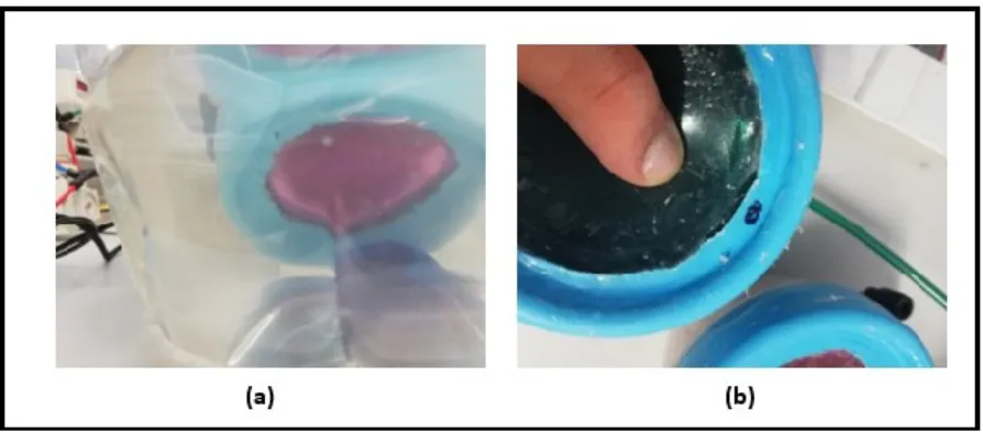
The main problem that earlier iterations presented was the presence of air leaks. Figure 14 presents an initial approach where the surface is composed by a cylindrical box and a silicone membrane. The surface was isolated by applying sealant to critical air leakage regions.
Figure 15 (a) presents a test performed on a surface A iteration: the surface was placed underwater and pressurized to check for air leaks. The silicone membrane was stuck between the box and its lid, and the lid had a hole in its centre to allow for user interaction. Air leaks were found on the area where the adhesive sealant was applied, between the surface lid and the silicone membrane. Figure 15 (b) presents a closer inspection of the surface where it can be observed that the adhesive sealant had detached from the surface in those areas, possibly when vacuum was applied or when the user interacted with the surface by applying an external force, with the finger.
Design and prototyping of Haptic Surfaces
For surface A, the final solution, presented in Figure 16, consisted of a 200mL cylindrical plastic box with a silicone lid (ÖVERMÄTT, Ikea) and an adhesive sealant tape (General Sealants) applied between the plastic and the silicone. The surface was tested by setting a vacuum pressure of 0.90 bar, holding it with a non-return valve, and measuring, with a timer and visual inspection of the pressor sensor display, the time it took for the pressure to decrease by 0.10 bar. Additionally, the time was registered every 0.01 bar drop and the test stopped when the sensor displayed 0.80 bar. Under these conditions, the surface’s internal vacuum pressure took an average of 3 minutes to decrease 0.01 bar.
In this configuration it is also easier to change between granular material when compared with previous iterations, as the adhesive sealant tape used is reusable. As such, to change material, the silicone lid is removed, with no effort, the previous material is drained and a new one can be introduced. To close the surface, the lid is adjusted to the container and pressed against the adhesive tape.
Figure 15 - Test for leaks on an early surface A prototype (a) and detected air leaks (b)
Design and prototyping of Haptic Surfaces
20
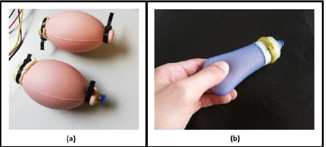
For surface B enclosures silicone pumps used in perfumes (Figure 17a) and silicone bottles (Figure 17b) were considered. After filling both with granular material it was quickly realized that the silicone pumps had a thicker membrane that did not allow for a clear perception of the granular material’s stiffness, being considerably stiffer than the bottles at normal air pressure. As such the 60 mL silicone bottles, like the one presented in Figure 17, were chosen for surface B.
To assure vacuum preservation, the General Sealant’s tape used for type A surfaces was applied inside the bottles between the silicone and the plastic, and around the outside of the threaded connection between lid and bottle. A threaded connector was inserted in a hole already present in the lid and, like in the type A surfaces, the thread was laced with Teflon and the outside of it isolated with glue. The previous test for airtightness was also performed for surface B. In this case the surface’s vacuum pressure took an average of 1 minute to decrease 0.01 bar. For the purpose of this work, surfaces A and B were filled with seven types of granular material and submitted to particle jamming. Four of these materials were selected, based on previous studies presented in Chapter 3, for indentation tests that aimed to characterize stiffness for different levels of vacuum; coffee grounds of medium coarseness, decorative sand, sugar and couscous. The other three were two different types of Styrofoam spheres (varying in size) and small plastic beads (irregularly shape with approximate diameters varying between 3 and 6 mm).
Design and prototyping of Haptic Surfaces
To summarize the main properties for each surface type are listed in Table 3.
Table 3 - Proprieties of the selected haptic surfaces
Surface Type A B Volume (mL) 200 60 Membrane thickness (mm) 1 2 Airtightness * (min) 30 10
Silicone Region Top circular area of the plastic box
External surface area of the silicone volume
Main type of Interaction Finger Hand
Material Fillings tested Sugar, “Couscous”, Decorative Sand and Coffee grounds
*airtightness represents the time it takes for the vacuum pressure inside the enclosure to decrease by 0.10 bar. For a minimal test volume, airtightness is greater than 60 minutes.
4.2 Control Solutions
Two control solutions were used to create and adjust vacuum inside the surfaces: a “fixed” system that requires an external source of compressed air and that can be digitally controlled, and a portable solution that is manually controlled. The “fixed” system was used to experiment with adjustable stiffness in the workplace and for the final demonstrative software application, detailed in Chapter 5. The portable solution was used in the experimental evaluations since the tests were done in an environment without a source of compressed air.
The first system, presented in Figures 18 and 19, was idealized to provide a digitally controlled system. For vacuum generation, a vacuum ejector (SMC ZH10B) that provides a maximum pressure of 0.90 bar was used. For pressure control, the system included a manual pressure regulator (SMC AR20-F01BE-B) and an electro pneumatic regulator (ITV2050). For pressure measurement the system has three digital pressure switches (SC ISE40A-N01-R).
Design and prototyping of Haptic Surfaces
22
The system is controlled by an Arduino microcontroller (Arduino Mega 2560). To avoid the contamination of particles into the pneumatic tubes, a paper filter was placed inside the container at the entrance of the pneumatic connector. The compressed air source available at the workplace provided a pressure of 6 bar.
Vacuum level is adjusted by sending a voltage signal to the digital regulator that adjusts the positive pressure at the inlet port of the ejector. Three different values of pressure were measured in the circuit: the pressure at the inlet port of the digital regulator and the vacuum pressure inside surface are monitored by the digital switches. The pressure at the inlet port of the vacuum injector is displayed in the digital pressure sensor.
Figure 18 - Pneumatic system for digital control of vacuum pressure
Design and prototyping of Haptic Surfaces
The portable solution, presented in Figure 20, was composed by a 12 VDC vacuum pump with a maximum output of 0.85 bar of vacuum pressure, a unidirectional restrictor valve (“MECMAN”) for vacuum pressure control and a digital switch for vacuum pressure monitoring. In this solution, to achieve a desired vacuum pressure, a toggle manual switch controls the pump, and vacuum level is adjusted in the restrictor valve. When the pressure sensor displays the desired pressure, the restrictor is manually closed, and the pump is turned off.
4.3 Experimental Tests
Stiffness tests were carried out on the developed Haptic Surfaces using the portable control solution. Due to the soft nature of the silicone membranes used, indentation tests were chosen for characterizing surface’s stiffness when operating at distinct vacuum pressure levels. The indentation test is one of the most frequent methods performed for the evaluation of soft tissue’s stiffness [22]. The test applies a constant low velocity movement of a probe against the surface, while measuring force and displacement. The movement stops when a selected value of force or displacement is reached. At this point the test may be considered concluded or it may be continued by reverting the movement and registering values of force and displacement until no force is detected. This is done to obtain the hysteresis characteristics of the system.
The goal of the tests was to explore particle jamming by evaluating how the stiffness of each solution (A and B) changes with different types of granular material for a fixed series of vacuum pressures. This section is divided into three parts:
i. Materials tested; ii. Test Set-up; iii. Results.
Design and prototyping of Haptic Surfaces
24
i. Materials Tested
To characterize surface’s stiffness and its behaviour for distinct vacuum levels, force vs displacement trials, where a known indenter was pressed against a defined spot in the surface, were performed on type A and type B surfaces for the following four fillings of granular material:
• Sugar;
• Decorative sand;
• Coffee Grounds of universal coarseness; • “Couscous”.
As mentioned, the selection of granular matter was primarily inspired by the data collected in previous Force/Displacement (or Stress/Strain) tests made in the particle jamming context [18],[21]. The “couscous” particles were irregularly shaped spheres with a diameter ranging between 0.5 and 2.0 mm. The particles of the other three materials were regularly shaped spheres with a diameter inferior to 0.5mm. For the experimental evaluations, both A and B type enclosures were filled with granular material in a systematic way that minimized air presence without overfilling the enclosure.
ii. Test Set-up
The tests were conducted in the Laboratory of Biomechanics at Institute of Science and Innovation in Mechanical and Industrial Engineering (INEGI) that had no access to compressed air, which result in the need for the portable pneumatic solution based on a small vacuum pump. The surfaces are required to be in a stable position during the trials as any movement in the surface will cause inaccurate results. For surface A, the container was inserted in an identical box that acts as a support for both the surface and the pressure sensor. In this case, presented in Figure 21, and because the forces reached in these trials are relatively small (35 N maximum), there is no need for additional support.
Design and prototyping of Haptic Surfaces
Surface B requires complementary support, since the silicone bottles do not have a flat surface and, if no additional support was used, the surface would tip compromising the test. Figure 22 presents the 3D printed piece designed to support this type of surface during the indentation tests.
The set-up used for the indentation tests can be observed in Figure 23. It includes a high accuracy miniature Z-beam load cell with a 100 N capacity with an attached testing probe with a rectangular surface contact area of (10 x 2)mm2, a linear actuator (MP-20 Micro Pusher) that
registers the indenter position and imposes a test velocity of 10 mm/min. The tests were run in a specific software, designed for operating the system, to define the trial parameters and register the results.
Figure 22 - 3D designed (a) and printed (b) support for surface B indentation tests
Design and prototyping of Haptic Surfaces
26
The software offers different modes to run the indentation test. The experimental test results presented in this chapter were obtained by selecting only one of these modes. In the selected test, the user sets a fixed speed for the linear actuator to move downwards, pressing the indenter against the surface being tested. Data for the actuators’ position and cell’s load is registered in real time with a frequency set by the user. When the maximum force, set by the user, is reached, the actuator stops and inverts its movement with the same fixed speed. The test, and data acquisition, finishes when the indenter stops contacting the surface and, consequently, when the force registered is null. Figure 24 illustrates the working principle of this type of indentation test, by presenting the registered variation of displacement and force for a surface A prototype, filled with decorative sand, during one test at atmospheric pressure. The data acquisition frequency was set to 50Hz and the tests were initiated by a pre-load of 0.33 N.
The speed was set to 10 mm/min. This choice is justified by the fact that it is slow enough for the tests to be considered static and to allow minimal error when registering the test hysteresis, by assuring a no-slip condition of the indenter. The maximum force was set to 35 N for all tests, except tests done on type A surfaces at atmospheric pressure. In this scenario, the maximum force of 15 N was selected to avoid tearing of the thin silicone membrane during the test. The data presented in Figure 24 confirms the expected behaviour of the indenter’s speed: the calculated average speed with this data was of 10.125 mm/min for the descend movement and -9.95 mm/min and for the ascending movement of the testing probe.
To test the four materials and the two types of containers selected: Eight prototypes were tested for nine levels of vacuum pressure. Each of them was submitted to nine levels of vacuum pressure and so, a total of nine indentation tests were performed on each prototype. Additionally, a set of five tests (five levels of vacuum pressure) was performed for a surface B prototype, to demonstrate the differences between the stiffness felt in the “side” of the bottle and on its wider “front” area. Note that for all other tests using surface B the testing spot was on the front region.
Figure 24 - Time distributions of Force and Displacement, for surface A prototype with sand, at atmospheric pressure
Design and prototyping of Haptic Surfaces
For type A surfaces the tests were made approximately at the centre of the circular surface; for type B surfaces the tests were conducted, in both the front and side regions in the proximity of the centre of mass. Figure 25 presents the locations of this point for the front and side region respectively.
Table 4 presents a summary of the tests performed. The selection of vacuum levels was inspired by similar tests detailed in other jamming related articles [13], [14], [15] [18], [21], [13], [21]. It also aimed to cover a reasonable range of vacuum pressure to study the evolution of surface’s stiffness with vacuum. For the tests performed on the side region of surface B, the selection was based on previous tests of the surface’s front region.
Table 4 - Indentation tests performed
Surface(/s) Materials Tested Vacuum Pressures
(bar) indentation tests Number of
A and B (front) Sugar “Couscous” Decorative Sand Coffee grounds 0 | 0.05 | 0.10 0.15 | 0.20 | 0.35 0.50 | 0.65| 0.80 72 (2 surfaces * 4 materials * 9 vacuum levels) B (side) “Couscous” 0 | 0.05 | 0.15 0.20 | 0.80 5 Figure 25 - Testing location for surface B in the frontal area (a), and side area (b)
Design and prototyping of Haptic Surfaces
28
iii. Results
The indentation tests performed enabled to:
• Compare the distribution of stiffness with vacuum pressure between different materials and enclosures;
• Find adequate filling materials for surfaces A and B, with stiffness range as the primary criteria;
• Compare stiffness of two different zones for B type surfaces: upwards and sideways.
To compare changes of stiffness with vacuum pressure between the different tested materials, for both types of surfaces, a variable “S” was created and calculated for each test, where:
S = Fmax / Lmax; (1)
“Fmax” is the maximum force registered in the test and “Lmax” is the correspondent
maximum surface deflection registered during the test. This is based on the “Effective” Flexural Modulus concept presented in article [18].
The defined S variable serves only as a term of comparison between these tests and does not provide any faithful information outside this context. This is justified as the materials do not present a purely elastic behaviour which makes the formula used to calculate S a rough estimation for a stiffness value. The graphics presented in Figures 26 and 27 show the evolution of the mentioned S variable with vacuum pressure. They can be used to compare the two types of surfaces and the four types of granular matter. Additionally, the S variable’s distribution with vacuum pressure is a good indicator of stiffness range.
0 5 10 15 20 25 30 0 0.05 0.1 0.15 0.2 0.35 0.5 0.65 0.8 S (N /m m )
Vacuum Pressure (bar)
Type A
Coffee Sugar CousCous Sand
Design and prototyping of Haptic Surfaces
From the data summarized in Figure 26 and Figure 27 it is concluded that:
• The S variable shows a non-linear distribution with pressure. For surfaces filled with sand, this distribution follows an approximately linear path;
• The S value distributions usually follow a similar path, but with different values, when comparing the same material for the two surfaces;
• The S values obtained for surface B are typically greater than for surface A, particularly when comparing between low levels of vacuum pressure. This indicates an overall higher stiffness for surfaces B, due primarily to their greater membrane thickness;
• For surfaces A (plastic box closed with a silicone lid): both sand and “couscous” show an identical maximum stiffness (S value) for the point of maximum vacuum pressure (0.8 bar). However, stiffness distribution with pressure for sand follows a more linear behaviour when compared with “couscous”. This indicates a more balanced distribution of stiffness with pressure for this material, which may be beneficial depending on the application;
• For surfaces B (silicone bottle): In this case sugar proves to be the material capable of achieving the highest stiffness followed by couscous and then by sand;
• In both cases: coffee grounds show the smaller stiffness range, according to variable S, making it more difficult to distinguish between different surface rigidities. This was also felt when handling the coffee filled surfaces. However, for high vacuum pressures the stiffness felt for these surfaces was very similar to that of any of the other materials. This can either be due to the documented difference between stiffness and its perception as it can also be attributed to the inherent limitations in the definition of variable S.
0 5 10 15 20 25 30 0 0.05 0.1 0.15 0.2 0.35 0.5 0.65 0.8 S (N /m m )l
Vacuum Pressure (bar)
Type B
Coffee Sugar CousCous Sand
Design and prototyping of Haptic Surfaces
30
a) Surface A
For surface A, decorative sand was selected as the ideal material, as it granted the highest range for the S variable. Also, the S value followed a near linear behaviour, which could indicate a better control of stiffness level. Figure 28 presents the force-displacement curves from the nine saw-tooth tests for surface A with decorative sand.
From the curves presented in Figure 28, further conclusions can be drawn:
• For higher vacuum pressures, it is observed that the curves start to converge, meaning that, after a certain vacuum level, the surface’s stiffness changes become harder to distinguish;
• For a force of 30 N, four points can be distinguished by having measured displacements greater than 1 mm between them for different levels of vacuum pressure: [0.05; 0.10; 0.20; 0.80] bar. Of those points, the maximum displacement registers approximately 4.7 mm (0.05 bar) whereas the minimum indicates a displacement of approximately 1.3 mm (0.8 bar). Considering that the forces applied during a touch interaction are usually somewhere between 20 and 40 N, this could potentially indicate the capability to distinguish four levels of surface stiffness;
• It can be estimated that, for atmospheric pressure, the deflection for 30 N would surpass 8 mm. This is more than 3 mm greater than the displacement for 0.05 bar which potentially indicates an extra level of surface stiffness to the previously mentioned four (total of five levels);
0 5 10 15 20 25 30 35 40 45 0 1 2 3 4 5 6 7 8 Force (N) Displacement (mm)
Type A- Decorative Sand
0 Bar* 0.05 Bar * 0.10 Bar * 0.15 Bar * 0.20 Bar * 0.35 Bar * 0.50 Bar * 0.65 Bar * 0.80 Bar *
Design and prototyping of Haptic Surfaces
• Although the tests were set to stop when a maximum force of 35 N was reached, higher values were registered; since the tests are done at a constant speed (10 mm/min), it is observed that the force increment is too fast when the surface is too stiff, which is to say when the displacement is too small, which leads to a few readings (usually 3 or 4, for a data acquisition of 50Hz) above the set limit, this can be seen through all obtained graphics;
• The hysteresis non-linear curves were expected from what was reported in previous articles [14], [21]. The authors Stanley, Gwilliam, and Okamura [14] observed this for coffee particles and attributed it to the tendency of coffee grounds to hold shape unless disturbed by an external force. Sand particles are similar in size and shape to coffee grounds that can justify the same type of behaviour;
• Certain irregularities can be seen in the curves, especially those that identify lower vacuum pressures. These irregularities may be attributed to particle rearrangement that would be more noticeable for less stable particle structures, more susceptible to deformation. This can be supported by the fact that the curves become increasingly more regular and uniform with increasing vacuum, meaning that, for a certain level of compaction the granular material displays a more stable internal structure, becoming immune to particle deformations as was discussed in Chapter 3.
b) Surface B
For surface B, “couscous” was the selected material. “Couscous” and sugar showed similar range for the S variable, however “couscous” was ultimately chosen for its quicker stiffness response when transitioning between jamming levels. In fact, this material rapidly returned to its natural form when submitted to atmospheric pressure after being compacted, while the other materials didn’t. Coffee and sugar particles suffer permanent “deformation” when compacted; when atmospheric pressure is installed again, the air does not fill the same spaces as it previously did as the particles are too small and compacted. Figure 29 presents force-displacement curves from the nine saw-tooth tests for surface B with “couscous”.
![Figure 3 - Visual interface for Bed of Nails (a) and Formable Crust device (b) [10]](https://thumb-eu.123doks.com/thumbv2/123dok_br/15670782.1061847/25.892.207.729.749.960/figure-visual-interface-bed-nails-formable-crust-device.webp)
![Figure 4 - Four examples of Haptic devices based on particle jamming [8]](https://thumb-eu.123doks.com/thumbv2/123dok_br/15670782.1061847/26.892.263.582.264.534/figure-examples-haptic-devices-based-particle-jamming.webp)
![Figure 6 - Vacu-Sl’s working principle [13]](https://thumb-eu.123doks.com/thumbv2/123dok_br/15670782.1061847/27.892.293.643.122.338/figure-vacu-sl-s-working-principle.webp)
![Figure 7 - Illustrations of particle interactions: Intrusion (a) and Hopping (b) [13]](https://thumb-eu.123doks.com/thumbv2/123dok_br/15670782.1061847/30.892.106.754.573.797/figure-illustrations-particle-interactions-intrusion-hopping-b.webp)
![Figure 11 - Stress vs Strain curves for different levels of vacuum pressure [18]](https://thumb-eu.123doks.com/thumbv2/123dok_br/15670782.1061847/34.892.247.583.267.539/figure-stress-strain-curves-different-levels-vacuum-pressure.webp)
![Figure 13 - Force/stress vs displacement/strain curves for coffee grounds [20]](https://thumb-eu.123doks.com/thumbv2/123dok_br/15670782.1061847/35.892.295.637.876.1134/figure-force-stress-displacement-strain-curves-coffee-grounds.webp)