Scientific Drilling, Special Issue No.1, 2007
11
Part 5 : Technological Challenges of Drilling, Testing, Sampling, and Monitoring in Fault Zones
Paradox
Hydraulic fracturing in a vertical borehole induces fractures that will be vertical and normal to the minimum horizontal stress Sh (parallel to the maximum horizontal
stress SH), if there is no influence of natural fractures. The
induced fractures close with venting and open with re-pressurization. At those times, there appear two kinds ofAt those times, there appear two kinds of there appear two kinds of critical borehole pressure, the reopening pressure, the reopening pressurethe reopening pressure Pr and the
shut-in pressure Ps, which characterize the variation of
borehole pressure during the test. The conventional theory tells us that those two pressures are related to the two stress components of SH and Sh as follows (Haimson and Cornet,and Cornet, Cornet,,
2003):
p H h
r
S
S
P
P
=
3
−
−
(1)h s S
P = (2)
Note that Pp is pore pressure in the fracture before
opening. Those two equations give the principle for the two values of SH and Sh to be determined from the two measured
pressures of Prand Ps.
The interpretation of Eq. (2) for Ps is supported by
consid-erable experimental and theoretical works. On the other hand, if the interpretation of Eq. (1) for Pr is also correct, the
measured values of Pr and Ps should change independently in
response to the combination of SH and Sh which will vary site
by site. However, the data of field tests so far indicate that incidences where the measured reopening pressure lies close to the shut-in pressure (i.e.,(i.e., Pr = Ps) are far more are far more
numerous than can reasonably be expected (Lee and Haimson, 1989). This strange phenomenon could happen if, 1989). This strange phenomenon could happen if 1989). This strange phenomenon could happen if the crust is in a stress condition of (SH - Pp)/(Sh - Pp) = 2.
Nevertheless, it is hard to consider that such a condition has been held everywhere in the crust. It may be more reasonable to consider that, contrary to the conventional theory, the measured reopening pressure does not coincide with the “true” reopening pressure (the borehole pressure at which(the borehole pressure at whichthe borehole pressure at which the fracture truly begins to open from its mouth at the borehole wall) and that pressure takes the same value with) and that pressure takes the same value with and that pressure takes the same value with the shut-in pressure (i.e., with(i.e., with with Sh). If this is true, we could. If this is true, we couldthis is true, we could is true, we could
estimate with hydraulic fracturing only the minimum component of stress Sh but not the maximum component of
stress SH, which is the most desired concern in the stress
measurement. Furthermore, a serious problem may occur may occur
should such a large error be included in the estimates ofsuch a large error be included in the estimates oflarge error be included in the estimates of be included in the estimates of included in the estimates of maximum stress SH based on the reopening pressure so far.
True and Apparent Reopening Pressures
In order to explain the paradox described above, we have to take into account two factors which have been ignored ininto account two factors which have been ignored inaccount two factors which have been ignored inve been ignored in been ignored inin all conventional theory. Those factors are (i) residual aperture of fracture, and (ii) hydraulic compliance of test, and (ii) hydraulic compliance of test and (ii) hydraulic compliance of test systems C. The C corresponds to an amount of fluid required to elevate fluid pressure in a test system by a unit magnitude, and it can be represented equivalently as C =ßVeff, where ß is
the fluid compressibility, and, and and Veff is the effective system
volume. While the details of explanation have been describeds of explanation have been described of explanation have been describedve been described been described by Ito et al. (1999, 2005, 2006), they can be outlined briefly as Ito et al. (1999, 2005, 2006), they can be outlined briefly asthey can be outlined briefly as can be outlined briefly asoutlined briefly as briefly as follows.
The residual fracture aperture causes pressure penetra-tion into the fracture prior to opening. Evidence of this hashas already been shown by laboratory studies (Cornet, 1982; shown by laboratory studies (Cornet, 1982;shown by laboratory studies (Cornet, 1982;n by laboratory studies (Cornet, 1982; Durham and Bonner, 1994; Zoback et al., 1977). The pressure, 1977). The pressure 1977). The pressure penetration will be almost wholly transmitted to the fracture surface since the net area of contact of the two surfaces is usually a small fraction of their nominal area. Thus, the third, the third the third component in Eq. (1) should be borehole pressure rather than Pp. The borehole pressure at fracture opening is defined
as Pr, and so substituting Pp with Pr in Eq. (1) yields
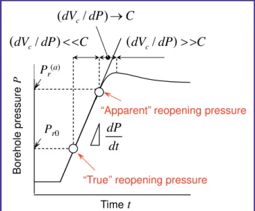
Figure 1. Effect of the system compliance C and fracture opening on borehole pressure variation.
Time
t
C
dP
dV
c/
dV
c/
dP
C
(
dV
c/
dP
)
→
C
dt
dP
P
r(a)P
r0“True” reopening pressure
“Apparent” reopening pressure
Borehole pressure
P
(
)
<<
(
)
>>
BABHY—A New Strategy of Hydrofracturing for Deep
Stress Measurements
by Takatoshi Ito, Kentaro Omura, and Hisao Ito
, and Hisao Ito
and Hisao Ito
11
Scientific Drilling, Special Issue No.1, 2007Part 5 : Technological Challenges of Drilling, Testing, Sampling, and Monitoring in Fault Zones
Part 5 : Technological Challenges of Drilling, Testing, Sampling, and Monitoring in Fault Zones
level of minimum stress Sh. However, it should be recalled
here that the compliance in concern is that of the volume between the flow meter and the fracture mouth. Taking thisthis into account, if the flow meter is placed as close as possible toaccount, if the flow meter is placed as close as possible to the test interval, as illustrated in Fig. 2, the system compliance, as illustrated in Fig. 2, the system compliance as illustrated in Fig. 2, the system compliance
C can be reduced drastically, and a more objective measure of flow entering the fracture can be obtained. In this case, it is not a matter of course what kind of tubing (drill pipe)—(drill pipe)—drill pipe)—)—— flexible tube or stainless pipe with small ID—is used to convey fracturing fluid from a pump to a test interval. To demonstrate this idea, we developed a test system with a downhole flow meter (Ito et al., 2002). The system is basically, 2002). The system is basically 2002). The system is basically the same as the conventional one except that the transducer to measure flow rate of injection is installed at the top of a straddle packer tool. Due to this modification, we succeeded in reducing the system compliance reducing the system complianceing the system compliance the system compliance C drastically. The straddle packer tool is conveyed in boreholes on 6-conductor wireline. A single high-pressure hose is used to supply pressure from a hydraulic pump at the ground surface to the packer elements and the straddle interval so that a switch valve controllable from the surface is attached to the straddle packer. The system is designed to use in a borehole with 101 mm (HQ size) diameter at depths up to 1 km.
However, such a modification as above is still not suffi-cient to achieve the stress measurement at depths more than 1 km because of the following reasons.following reasons.reasons.
(a) The stress measurement at deep depths cannot be done, of course, without deep boreholes, which generally, of course, without deep boreholes, which generally of course, without deep boreholes, which generally, without deep boreholes, which generally without deep boreholes, which generallywhich generally generallygenerally have a large diameter, and accordingly the straddle packerve a large diameter, and accordingly the straddle packer a large diameter, and accordingly the straddle packer tool needs to be large. The large size of the straddle packerneeds to be large. The large size of the straddle packer to be large. The large size of the straddle packer tool leads to an increase in the system compliancean increase in the system compliance increase in the system compliance C.
(b) For monitoring and recording flow rate and pressure during tests of the transducer installed on top of the straddleof the transducer installed on top of the straddle the transducer installed on top of the straddleon top of the straddle top of the straddle packer tool, the transducers should be connected with a data acquisition system placed at the ground surface by wires. To do this, it is appropriate to convey the straddle packer tool in
(
h H)
r
r P S S
P ≡ = 3 − 2 1 0
(3)
Thus, the effect of including pressure penetration into the, the effect of including pressure penetration into the the effect of including pressure penetration into the fracture prior to opening is to reduce the reopening pressure by a factor of almost two from the value expected using conventional theory (the reduction is precisely two when pore pressure is negligible). We will refer the borehole pressure given by Eq. (3) to the true reopening pressure
Pr0.
On the other hand, the influence of the compliance C on fracture opening is more problematic; it is concerned with; it is concerned with it is concerned withit is concerned with is concerned withis concerned withconcerned withed with the correct identification of the true reopening pressure from the borehole pressure P minus time t curves. Note that the reopening pressure is usually detected as the borehole pressure P at which the P - t curve is seen to deviate from linearity (Fig. 1). The effect of fracture opening on the borehole pressure variation can be expressed as follows (Ito et al., 1999):
(
dV
dP
)
C
Q
dt
dP
c
+
=
/
(4)where dVc is the change in pressurized fluid volume due to
fracture opening. Since the flow rate Q and the system compliance C are constant, Eq. (4) indicates that deviations of the P - t curve from linearity are governed by changes in the value of dVc/dP and its relative value with respect to C.
That is, prior to fracture opening, dVc/dP is zero and the
borehole pressure P increases linearly with t. After fracture opening, dVc/dP becomes greater than zero, and the P - t
curve will deviate from linearity to some degree or other. However, even if a flexible hydraulic tube with small ID (less(lessless than 10 mm) is used to convey fracturing fluid from a pump) is used to convey fracturing fluid from a pump is used to convey fracturing fluid from a pump to a test section in a borehole, C is considerably large. As a result, at the early stage of fracture opening, dVc/dP should
be very small compared with C so that no detectable change occurs on the P - t curve, as shown schematically in Fig 1., as shown schematically in Fig 1. as shown schematically in Fig 1. schematically in Fig 1. in Fig 1. When P reaches a level of Sh, the stress acting normally to
the fracture surface becomes almost equal to or less than the value of Sh anywhere. Such a balanced stress condition leads a balanced stress condition leadsbalanced stress condition leads
to the criticality that the fracture aperture increases abruptly with a small increment in borehole pressure. As aa small increment in borehole pressure. As asmall increment in borehole pressure. As ain borehole pressure. As a borehole pressure. As a result, dVc /dP becomes a larger value compared with C, and
finally the P -- t curve begins to deviate from the initial linear trend. The same process occurs regardless of the SH value.
Thus, we provide an explanation as to why incidences wherewe provide an explanation as to why incidences where provide an explanation as to why incidences where the apparent (or measured) reopening pressure coincides with Ps (i.e., the minimum stress(i.e., the minimum stress the minimum stress Sh are so common as
described above). We will denote hereafter the apparent). We will denote hereafter the apparent. We will denote hereafter the apparent reopening pressure as Pr(a).
A Strategy for the Maximum Stress
Measurements
Thus the strange observation of Pr(a) = Ps in field tests
arises because the compliance of typical hydraulic fracturing systems is far larger than that of fracture until P reaches a
Figure 2.A concept to reduce the system compliance C (i.e., the volume, Veff) by placing the flow meter just above the straddle packer tool.
Pump
Flow meter
Borehole
Induced
vertical fracture
V
effV
cPart 5 : Technological Challenges of Drilling, Testing, Sampling, and Monitoring in Fault Zones
Scientific Drilling, Special Issue No.1, 2007
115
Part 5 : Technological Challenges of Drilling, Testing, Sampling, and Monitoring in Fault Zones
boreholes on wireline. The use of wireline is also effective to save the time for the tool running in boreholes. However, as the depth of measurement becomes greater, so does the riskgreater, so does the risker, so does the riskso does the risk risk for the tool to become stuck in the borehole. The financialto become stuck in the borehole. The financial stuck in the borehole. The financialthe borehole. The financialborehole. The financialThe financial risk in losing the advantages of wireline logging is veryin losing the advantages of wireline logging is verylosing the advantages of wireline logging is verying the advantages of wireline logging is very the advantages of wireline logging is very severe. For this reason, the straddle packer tool has generallyFor this reason, the straddle packer tool has generally this reason, the straddle packer tool has generallygenerally been conveyed so far on drill pipe in the case of deepso far on drill pipe in the case of deepon drill pipe in the case of deepin the case of deep the case of deep measurement, but the use of drill pipe makes it hard to arrange the wires connecting the downhole transducers and the surface data acquisition system.
Realistic Proposal: BABHY
Such a dilemma could be solved by a new strategy appro-priate for the stress measurement at deep depths, as showns, as shown as shown in Fig. 3. There are two components used in the strategy:: (i) the compact drilling tool with a built-in mud motor, and, and and (ii) the straddle packer tool with a pump and a digital compass. Each is conveyed in drill pipe on wireline. The compact drilling tool is used to drill an additional hole,, several tens of millimeters in diameter and a few meters in of millimeters in diameter and a few meters in millimeters in diameter and a few meters in length, at the bottom of an original borehole, and the, at the bottom of an original borehole, and the at the bottom of an original borehole, and the, and the and the hydraulic fracturing is carried out in the drilled hole by using the small packer tool. The additional hole and the original borehole are referred to the “baby” hole and the “mother” hole, respectively. The procedure can be outlined as follows., respectively. The procedure can be outlined as follows. respectively. The procedure can be outlined as follows.outlined as follows. as follows..
i) Set drill pipe with coring bit in the mother hole.
ii) Lower the compact drilling tool in drill pipe on wireline and fix it onto the drill pipe.to the drill pipe. the drill pipe.the drill pipe.drill pipe.
iii) Pump drilling mud through the drill pipe to drive the muddrill pipe to drive the mud motor in the compact drilling tool, and drill the baby hole at the bottom of the mother hole.
iv) Retrieve the compact drilling tool and the small core, inspect pre-existing fractures in the core, and determine the depth of test section(s) in the baby hole.
v) Lower the straddle packer tool in the drill pipe on wireline, andthe drill pipe on wireline, anddrill pipe on wireline, and fix it onto the drill pipe.to the drill pipe. drill pipe.
vi) Lower the drill pipe slightly tothe drill pipe slightly todrill pipe slightly to squeeze the packer element for isolating the test interval, and pressurize the test interval to induce axial fractures by using the pump installed in the tool. During the test, the pressure and flow rate of injected fluid and the tool orientation are monitored by the transducers installed in the tool and transmitted through wireline to the data acqui-sition system at the surface.
vii) Retrieve the straddle packer tool while leaving the orien-tation marker at the bottom of the baby hole.the bottom of the baby hole.bottom of the baby hole.
viii) Lower and set a core barrel, and drill out the test section for getting the big core.
ix) Retrieve the big core, and inspect the fractures induced by pressurization in step (vi). The fracture orientation can bein step (vi). The fracture orientation can be step (vi). The fracture orientation can be determined from the orientation marker in the core and the tool orientation recorded in step (vi).in step (vi). step (vi).
Subsequently,, thethethe reopening pressure Pr(a)
and the shut-in pressure
Ps will be detected from
the records of pressure and flow rate during the test. Finally, the stress, the stress the stress magnitudes SH and Sh
will be estimated fromfrom those detected pressures based on Eqs. (2) and (3), assuming, assuming assuming Pr(a) = Pr0, since the system compliance is to be sufficiently small, andsmall, and the stress orientation will be estimated from the fracture orientation
Figure 4. The compact size of the BABHY system makes it easy to find the test section free from pre-existing fractures.
Drill rod Wire line
(Conventional) (Proposed, BABHY)
(a few meters)
~ 0.7 m
Figure 3. Proposed new strategy, BABHY, to achieve stress measurements by hydraulic fracturing at depths of more than 1 km, and its procedures. The procedure consists of three parts as follows: (i–iv), drilling the baby hole; (v–vii), in situ testing of hydraulic fracturing; and (viii–ix), extending the mother hole and retrieving the large core.
(iii)
(i) (ii) (v) (vi) (vii) (viii)
“Mother” hole
“Baby” hole
Induced fracture
Orientation marker “Small” core
“Big” core Fixing tool
fe
w
m
e
te
rs
(iv)
Downhole mud motor
Pumping system with compass
(ix)
116
Scientific Drilling, Special Issue No.1, 2007Part 5 : Technological Challenges of Drilling, Testing, Sampling, and Monitoring in Fault Zones
detected in step (ix). We call this strategy Baby Boreholein step (ix). We call this strategy Baby Borehole step (ix). We call this strategy Baby Borehole Hydrofracturing, BABHY for short.
This strategy will allow us to improve many defects in the conventional method as follows. It is easy to reduce the system compliance sufficiently because of a very compact size of the straddle packer tool (Fig. 4). The test section being free from pre-existing fractures can be chosen withwith certainty by the inspection of the small core, and then thety by the inspection of the small core, and then they by the inspection of the small core, and then the, and then thehen the straddle packer tool can be adjusted as the pressurized interval to be located at the chosen test section rightly. Note that the axial length between the top of the upper packer element and the bottom of the lower packer element is very short (less than 1 m) compared with that of a few meters for(less than 1 m) compared with that of a few meters forless than 1 m) compared with that of a few meters for) compared with that of a few meters forcompared with that of a few meters for a few meters for few meters for the conventional tool. The shorter length will make it muchmuch easier to choose the test section. We have already completedhave already completedcompleted development of the compact drilling tool, and we are nowment of the compact drilling tool, and we are now the compact drilling tool, and we are now developing the straddle packer tool. They are designed to be used in the mother holes with diameters larger than 101 mms larger than 101 mm larger than 101 mm (HQ size). As a part of the development process, we carried process, we carried, we carried out a field test to confirm the procedure of step (vi) in in particular (installing the straddle packer in the baby hole (installing the straddle packer in the baby hole(installing the straddle packer in the baby holeinstalling the straddle packer in the baby hole and carrying out hydraulic fracturing) at the Kamioka mine) at the Kamioka mine at the Kamioka mine in Japan. For this test, we used a vertical borehole with 123 mm (PQ size) diameter and about 30 m deep drilled from thedeep drilled from the drilled from the floor of a chamber at a depth of about 500 m from the grounda depth of about 500 m from the ground depth of about 500 m from the ground surface. The baby hole with 47 mm (AQ size) diameter and 1 m length was drilled at the bottom of the borehole. The test succeeded quite well so that a pair of typical fractures in quite well so that a pair of typical fractures inquite well so that a pair of typical fractures in well so that a pair of typical fractures in axial direction was induced, and the shape and orientation of the induced fractures were clearly detected from the largeclearly detected from the largedetected from the largelarge retrieved core (Fig. 5).5).).
References
Cornet, F.H., 1982. Analysis of injection tests for, 1982. Analysis of injection tests for 1982. Analysis of injection tests for in situ situsitu stress
deter-mination. In Zoback, M.D., Haimson, B.C., and Jacobson,
M.L. (Eds.), Proceedings of Workshop XVII, Workshop oneedings of Workshop XVII, Workshop on Workshop XVII, Workshop onXVII, Workshop on Hydraulic Fracturing Stress MeasurementFracturing Stress Measurementracturing Stress Measurement. Menlo Park, Calif., Calif. (The Survey), 414–443. 414–443.
Durham, W.B. and Bonner, B.P., 1994. Self-propping and fluid flow in, B.P., 1994. Self-propping and fluid flow in., 1994. Self-propping and fluid flow in, 1994. Self-propping and fluid flow in 1994. Self-propping and fluid flow in
slightly offset joints at high effective pressures. J. Geophys.
Res., 99:9391–9399. 99:9391–9399.
Haimson, B.C. and Cornet, F.H., 2003. ISRM suggested methods for, 2003. ISRM suggested methods for 2003. ISRM suggested methods forsuggested methods foruggested methods formethods forethods for rock stress estimation – Part 3: hydraulic fracturing (HF) and / or hydraulic testing of pre-existing fractures (HTPF). Int. J. Rock Mech. Min. Sci., 40:1011–1020. 40:1011–1020.
Ito, T., Evans, K., Kawai, K., and Hayashi, K., 1999. Hydraulic fracture, T., Evans, K., Kawai, K., and Hayashi, K., 1999. Hydraulic fracture T., Evans, K., Kawai, K., and Hayashi, K., 1999. Hydraulic fracture, Kawai, K., and Hayashi, K., 1999. Hydraulic fracture Kawai, K., and Hayashi, K., 1999. Hydraulic fractureK., and Hayashi, K., 1999. Hydraulic fractureand Hayashi, K., 1999. Hydraulic fracture, K., 1999. Hydraulic fracture., 1999. Hydraulic fracture, 1999. Hydraulic fracture 1999. Hydraulic fracture reopening pressure and the estimation of maximum horizontal stress. Int. J. Rock Mech. Min. Sci. & Geomech. Abstr. 36:811–826.
Ito, T., Igarashi, A., Ito, H., and Sano, O., 2006. Crucial effect of system, T., Igarashi, A., Ito, H., and Sano, O., 2006. Crucial effect of system T., Igarashi, A., Ito, H., and Sano, O., 2006. Crucial effect of systemA., Ito, H., and Sano, O., 2006. Crucial effect of systemIto, H., and Sano, O., 2006. Crucial effect of system, H., and Sano, O., 2006. Crucial effect of system and Sano, O., 2006. Crucial effect of system, O., 2006. Crucial effect of system., 2006. Crucial effect of system, 2006. Crucial effect of system 2006. Crucial effect of system compliance on the maximum stress estimation in the hydro-the hydro- hydro-fracturing method: Theoretical considerations and field-tests and field-test and field-test-testtest verification. Earth Planets Spaces Space Space,58:963–971.
Ito, T., Kato, H., Karino, H., and Hayashi, K., 2002. Hydrofrac stress, T., Kato, H., Karino, H., and Hayashi, K., 2002. Hydrofrac stress T., Kato, H., Karino, H., and Hayashi, K., 2002. Hydrofrac stress, Karino, H., and Hayashi, K., 2002. Hydrofrac stress Karino, H., and Hayashi, K., 2002. Hydrofrac stress, H., and Hayashi, K., 2002. Hydrofrac stress and Hayashi, K., 2002. Hydrofrac stress, K., 2002. Hydrofrac stress., 2002. Hydrofrac stress, 2002. Hydrofrac stress 2002. Hydrofrac stress measurements on true reopening pressure and development
a system for the measurements at depths up to 1000 m. In
Choi, S.-Y., et al (Eds.), Proceedings of 2002 ISRM Regionaleedings of 2002 ISRM Regional 2002 ISRM Regional Symposium on Rock Engineering Problemsosium on Rock Engineering Problems Rock Engineering Problemsineering ProblemsAnd Approaches innd Approaches in Underground Construction, 93–100. 93–100.
Ito, T., Igarashi, A., Ito, H., and Sano, O., 2005. Problem for the, T., Igarashi, A., Ito, H., and Sano, O., 2005. Problem for theProblem for the maximum stress estimation by hydraulic fracturing methodaulic fracturing methodfracturing method and its potential solution. Proceedings of 40eedings of 40 4040th U.S. RockU.S. Rock.S. RockS. Rock. Rock Rock Mechanics Symposiumanics Symposium Symposiumosium,Anchorage, Alaska: ARMA/USRMS, Alaska: ARMA/USRMS: ARMA/USRMS 05-862 (CD-ROM).
Lee, M.Y. and Haimson, B.C., 1989. Statistical evaluation of hydraulic, M.Y. and Haimson, B.C., 1989. Statistical evaluation of hydraulic M.Y. and Haimson, B.C., 1989. Statistical evaluation of hydraulic, B.C., 1989. Statistical evaluation of hydraulic., 1989. Statistical evaluation of hydraulic, 1989. Statistical evaluation of hydraulic 1989. Statistical evaluation of hydraulic
fracturing stress measurement parameters. Int. J. Rock
Mech. Min. Sci. & Geomech. Abstr., 26:447–456, 26:447–456, doi::10.1016/0148-9062(89)91420-4.
Zoback, M.D., Rummel, F., Jung, R., and Raleigh, C.B., 1977.F., Jung, R., and Raleigh, C.B., 1977.Jung, R., and Raleigh, C.B., 1977. R., and Raleigh, C.B., 1977. and Raleigh, C.B., 1977., C.B., 1977.., 1977., 1977. 1977. Laboratory hydraulic fracturing experiments in intact and
pre-fractured rock. Int. J. Rock Mech. Min. Sci. & Geomech.
Abstr.,, 14:49–58, doi:10.1016/0148-9062(77)90196-6.
Authors
Takatoshi Ito, Institute of Fluid Science, Tohoku University,
2-1-1 Katahira Aoba-ku Sendai, 980-8577, Japan, e-mail: ito@ ifs.tohoku.ac.jp.
Kentaro Omura, National Research Institute for Earth
Science and Disaster Prevention, Tennodai 3-1, Tsukuba, Ibaraki 305-0006, Japan.
Hisao Ito, Japan Agency for Marine-Earth Science
Technology (JAMSTEC), 3173-25 Showa-machi, Kanazawa-ku Yokohama, Kanazawa, 236-0001, Japan.
Figure 5. “Small” core (AQ size) retrieved by the baby hole drilling and “big” core (PQ size) retrieved by the over-coring. Hydraulically-induced fractures appeared in the big core.
“Small” core