This article was published in Energy and Environmental Science, 7 (12), 4044-4052, 2014.
http://dx.doi.org/
10.1039/c4ee02160f
On the stability enhancement of cuprous oxide water splitting
photocathodes by low temperature steam annealing
J. Azevedo,
abL. Steier,
cP. Dias,
bM. Ste
fi
k,
dC. T. Sousa,
bJ. P. Araújo,
bA. Mendes,
aM. Graetzel
cand S. D. Tilley*
ca
LEPABE
–
Faculdade de Engenharia, Universidade do Porto, Rua Dr Roberto Frias,
4200-465 Porto, Portugal
b
IFIMUP and IN-Institute of Nanoscience and Nanotechnology, Departamento
de F´ısica
e Astronomia, Universidade do Porto, Rua do Campo Alegre 687, 4169-007 Porto,
Portugal
c
Institut des Sciences et Ingénierie Chimiques, Ecole Polytechnique Fédérale de
Lausanne (EPFL), CH-1015 Lausanne, Switzerland. E-mail: [email protected]
d
Department of Chemistry and Biochemistry, University of South Carolina, Columbia,
South Carolina, 29208, USA
Given the intermittent nature of solar radiation, the large-scale use of solar energy requires an efficient energy storage solution. So far, the only practical way to store such large amounts of energy is in the form of a chemical energy carrier, i.e., a fuel. Photoelectrochemical (PEC) cells offer the ability to convert solar energy directly into chemical energy in the form of hydrogen. Cuprous oxide (Cu2O) is being investigated for photoelectrochemical solar water splitting since
it has a band gap of 2.0 eV with favorable energy band positions for water cleavage; it is abundant and environmentally friendly. A major challenge with Cu2O is its limited chemical
stability in aqueous environments. We present a simple and low-cost treatment to create a highly stable photocathode configuration for H2 production, consisting of steam treatment of
the multilayer structures. The role of this treatment was investigated and the optimized electrodes have shown photocurrents over - 5mA cm-2 with 90% stability over more than 50 h
Introduction
Due to the emerging necessity to find sustainable alternatives to fossil fuels, numerous investigations are being conducted in order to find efficient means to extract energy from the largest renewable energy source, the Sun. One of the biggest challenges with solar energy is that it is only available during daytime. Hence, the large-scale use of solar energy requires an efficient energy storage solution. So far, the only practical way to store such large amounts of energy is in the form of a chemical energy carrier, i.e., a fuel.
Photoelectrochemical (PEC) water splitting cells offer the ability to convert solar energy directly into chemical energy, stored in the chemical bonds of hydrogen and oxygen. Hydrogen is one of the prime candidates as a future energy carrier.1 It can be produced from renewable energy
sources by (photo)electrolysis of water, stored and transported, and then used in a fuel cell to generate electricity on demand, yielding water without generating any harmful by-products. Alternatively, the renewable hydrogen can be reacted with carbon dioxide to generate carbon-based fuels. PEC water splitting has been much improved since the initial reports,2,3 and
nowadays researchers aim at finding inexpensive, efficient and stable materials to perform PEC water splitting.4–10
Cuprous oxide, Cu2O, is abundant, cheap and environmentally friendly and it absorbs a
significant part of the solar spectrum with a 2 eV bandgap, with favorable energy band positions for water cleavage. It has good p-type conductivity and it can be processed by low-cost methods such as electrodeposition,11 thus fulfilling all the necessary criteria for a promising
photocathode, except for one – stability in aqueous environments.
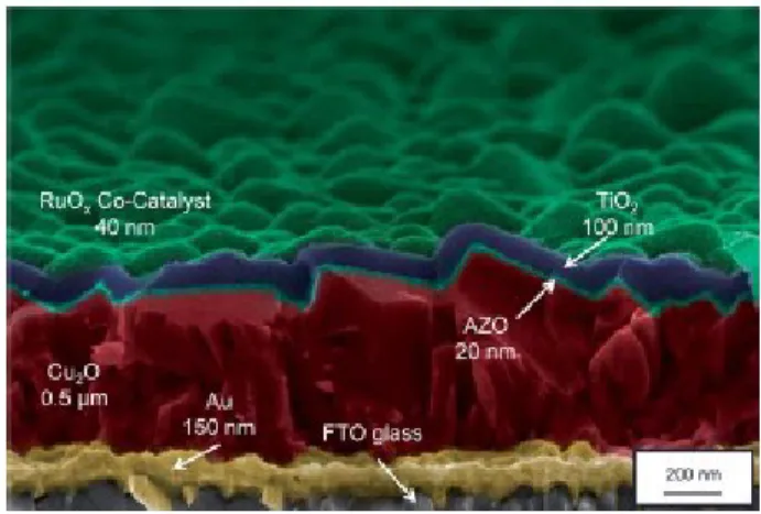
Recently, we have presented a multilayer configuration, using Cu2O as the photoactive material,
which addressed the instability problem of this material under working condi-tions.11,12 The
samples were prepared on gold-coated F:SnO2 (FTO) glass substrates. The photoelectrode consisted of a photovoltaic p–n junction of p-type Cu2O and n-type Al:ZnO (AZO) coated with a TiO2 protective layer, and activated for hydrogen evolution with electrodeposited Pt nanoparticles, producing photocurrents up to - 7.6 mA cm-2, under simulated solar AM 1.5
illumination when biased at 0 VRHE.11 Despite the conformal protective layer of TiO2 deposited
by atomic layer deposition (ALD), a decay of performance over the first 20 minutes was observed. No evidence of Cu2O degradation was observed and the photocurrent decline was
attributed to electron traps in the protective TiO2 aggravated by its amorphous state. Although the stability was still far from ideal, this configuration has revealed a new strategy that inspired us to investigate improved overlayers for better stability.
In the first approach, higher deposition temperature of the TiO2 ALD deposited layer revealed stability improvements.12 In that work, deposition of the TiO2 layer at 150 0C enhanced the
stability of the resulting photocathode when compared to the lower deposition temperature (120 oC). Furthermore, in a recent work on the detachment of platinum from the surface of the
biased at 0 VRHE during 8 h of light chopping.13 The improved catalyst/TiO2 interface allowed a
record-breaking stability of Cu2O-based photocathodes for water reduction.
From these previous reports, we developed an under-standing for the influence of TiO2 synthesis conditions on the photocathode stability. An alternative approach for further improving the photoelectrode stability targets improving the quality of the TiO2 protective layer with post-synthetic treatments. Heating the samples at high temperatures (400 oC) could
convert the amorphous TiO2 into a crystalline phase, which we expect would be more stable in the slightly acidic aqueous electrolyte. However, as the annealing temperature increases above 200 oC, the performance of the photocathode is diminished, perhaps due to the loss of doping
in the cuprous oxide, which is based on copper vacancies.
This work investigates an innovative low temperature steam treatment for improving the stability of Cu2O-based photo-electrodes protected with largely amorphous TiO2 layers. Low
temperature steam post-synthetic treatments were implemented, and have demonstrated greatly enhanced stabilities compared with non-treated samples. Photocurrents over 5 mA cm-2
were achieved with only a 10% loss over its initial photocurrent value during more than 50 h of light chopping (biased at 0 VRHE).
Experimental section
Electrodeposition of cuprous oxide
The working electrodes were fabricated on Au-coated TEC-15 F:SnO2 substrates (FTO, NSG
glass). FTO-glass was cut into 1 x 3cm2 pieces and then cleaned by sonication sequentially in
soapy water (15 min), acetone (15 min), ethanol (15 min), and finally in distilled water (15 min). The FTO was coated with 10 nm Cr, followed by 150 nm of Au (by sputtering). The Cu2O thin
films were electrodeposited from a basic solution of lactate-stabilized copper sulphate (pH = 12) at 30 oC, as described previously.15 A1 x 1cm2 area was left un-deposited to serve as electric
contact for experimental characterizations. The deposition conditions were optimized previously and galvanostatic electrodeposition was performed using a two-electrode configuration with Pt mesh as the counter electrode for 105 min at - 0.1 mA cm-2, resulting in a
Fig. 1 Cross-sectional SEM image of a photocatode with respective ALD layer thicknesses
Overlayer deposition
Very thin n-type oxide overlayers were deposited on top of the Cu2O using a thermal ALD system
(Savannah 100, Cambridge Nanotech). The exposed Au substrate was masked with Kapton® tape and the samples were rinsed with DI water and dried under compressed air prior to deposition. The Al:ZnO (AZO) (20 nm) and TiO2 (100 nm) were deposited as described previously.13
Steam treatment optimization
The steam treatment was carried out in a 100 mL Teflon autoclave. To identify the optimum conditions for the annealing of Cu2O (500 nm)/AZO (20 nm)/TiO2 (100 nm) samples to increase
stability, a systematic study of the effect of multiple variables was carried out. The amount of water, treatment duration and annealing temperature were varied and the optimum range of values identified. The samples were observed to be very sensitive to the amount of water in the autoclave, and they would easily dissolve at high temperatures. A small volume (200 L) of water was added to the autoclave and the sample was sus-pended in the vapor phase to avoid direct contact with water.
In order to identify the range of temperature and duration of steam treatment, a screening design was conducted between T Ε [100, 300] oC and t Ε [1, 8] h. For temperatures above 150 oC
and durations longer than 3 h the performance of the photo-cathodes was impaired (see examples in Fig. S1†). For lower temperature and duration, no signifcant change was observed when compared to untreated samples. A careful variation of the temperature (T) and duration (t) intervals with no sample deterioration was conducted with T between 100 oC and 150 oC and
Co-catalyst deposition
For the photoelectrochemical tests, RuOx and Pt catalysts were used, as described previously.13
Briefly, RuOx was deposited by galvanostatic photodeposition using 1.3 mM aqueous solution of
KRuO4 and a current density of 28.3 A cm-2 for 15 min under simulated one sun illumination.
Pt was deposited using the same technique with 1 mM solution of H2PtCl6 and a current density
of - 8.5 mA cm-2 for 15 min under simulated one sun illumination.
Thin film characterization
High-resolution scanning electron microscopy (both a FEI XL30 SFEG and also a Zeiss Merlin instrument) with a field emission source operated at 5 kV and a through-the-lens detector for secondary electrons was used to study the morphology of the photocathodes. The crystallinity was evaluated with a Bruker D8 Discover diffractometer, using monochromatic Cu Ka1 radiation (1.540598 A˚). The Bragg reflections were compared with values from the literature.16 Raman
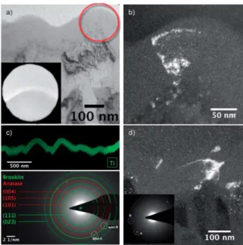
scattering measurements were made using a 532 nm wavelength laser beam and were acquired with a Labram HR800 model of Jobin-Yvon Horiba spectrometer equipped with a microscope for collection of backscattered Raman signals and phonon modes compared with references. 17,18 The thickness and n, k parameters of the ALD titania layer were evaluated using spectroscopic ellipsometry (Sopra GES 5E). The range of photo-energies used in the study was between 1.5 and 5.5 eV. The obtained spectra were fitted using the Tauc Lorentz dispersion law (WinELI software) to extract the thickness and n, k parameters of the deposited TiO2 layers. Transmission electron microscopy (TEM) measurements were carried out with a Technai Osiris (FEI, USA) in dark field and bright field modes. An acceleration voltage of 200 kV was applied. A 10 m selected area aperture was used to obtain diffraction patterns of a single layer. The camera length was 330 mm. Cross-section lamellae for TEM were prepared with a Zeiss NVision 40 CrossBeam with focused ion beam (FIB). Diffraction patterns were simulated using JEMS (Version 4.1520, CIME, EPFL, Switzerland).
Photoelectrochemical measurements
The photoelectrochemical performance of the photocathodes was studied using an Ivium Potentiostat/Galvanostat to acquire the photoresponse under chopped irradiation from a 450 W Xe-lamp (Osram, ozone-free) equipped with an IR/UV fiter (KG3filter, 3 mm, Schott), calibrated with a silicon diode in order to simulate AM 1.5 illumination (100 mW cm-2). A scan
rate of 10 mV s-1 in the cathodic direction was used to acquire the current–voltage data.
Measurements were carried out in a three-electrode configuration with the Cu2O
Results and discussion
TiO2 was proven to be an efficient protective overlayer for Cu2O photocathodes in previous
studies.11,13,19 Nevertheless, the stability of this photocathode is still far from that required for
commercial implementation. The biggest limitation in these systems results from electron trapping in the amorphous TiO2 layer, likely compensated by proton intercalation. We hypothesized that a crystalline overlayer would be more robust, and thus we sought to fabricate a system with a crystalline TiO2 overlayer. It is possible to grow crystalline TiO2 by ALD.20 However, heating the Cu2O/AZO junction to these temperatures (over 200 oC) hinders the
photoelectrochemical performance significantly.12 Post-synthetic heat treatments on a hot plate
or in a tubular furnace, in both atmospheric and inert environments led to similar deterioration of the performance. Thus, we have sought a low temperature method to alter the overlayer protective properties without damaging the photovoltaic properties of the semiconductor underlayers.
Hydrothermal treatments have been proven to be useful in the crystallization of oxide films,21
including TiO2,22 and commonly require temperatures less than 200 oC. Hydro-thermal
post-synthetic heat treatments were thus investigated. We found that the oxide materials were sometimes partially or completely dissolved when completely submerged in water in the autoclave at modest temperatures (150 oC). We therefore experimented with steam treatments
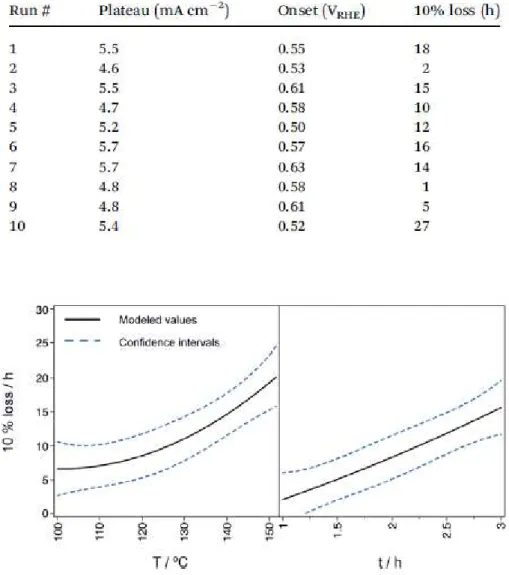
Table 1 Observed values of process responses. Stability is evaluated under continuous illumination measurement conditions
Fig. 2 Stability variation with steam treatment temperature (oC) and duration (h). Stability is evaluated – under continuous illumination measurement conditions – as the time it takes for the initial photo- current to drop to 90% of its initial value (a 10% loss). The black lines represent prediction profiles extracted from the statistical analysis on performed measurements and the blue dashed lines represent the corresponding confidence intervals.
Between 100 oC and 150 oC, a constant increase in stability with temperature and duration of
steam treatment is observed (Fig. 2). This is in accordance to what we expected since higher temperatures and annealing times should be related to a higher degree of crystallization. However, at temperatures greater than 150 oC or duration longer than 3 h a steep decrease in
semiconducting underlayers. We believe that at high temperatures the doping levels of Cu2O
(which are based on copper vacancies) are altered, thus affecting the performance.
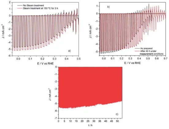
The highest stability was achieved at 150 oC for 3 h and the corresponding sample is
characterized in Fig. 3 and compared with a photocathode with no steam treatment. The onset is not significantly improved but a plateau photocurrent increase between 2% and 10% is observed in the steam treatment case (Fig. 3a). We previously reported the activation of the photo-electrodeposited catalyst after a few linear sweeps, accompanied with a fill factor improvement.13 With steam treatment, under measurement conditions, not only does the fill
factor increase, with a steep photocurrent increase at 0.5 VRHE, but also the onset is shifted
anodically by 70 mV (Fig. 3b). The stability is greatly enhanced, recording only 10% loss over 50 h biased at 0 VRHE in the pH 5.0 phosphate–sulfate electrolyte under light chopping (Fig. 3c). This
is by far the most stable Cu2O photocathode reported to date.
These results motivated us to study the reason for the improved performance. Park et al. have reported on the crystallization of semiconductor thin films with hydrothermal treatments.21
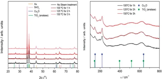
Improved crystallinity in the TiO2 would explain the superior performance as it is more resistant to electron trapping and/or etching in the slightly acidic medium. XRD and Raman spectra were obtained on photocathodes with different steam treatments to search for crystalline phases (Fig. 4). XRD spectra were unable to identify any TiO2 crystallization, even for samples that were subjected to extreme conditions, and were quite similar to photocathodes with no steam treatment.12 Raman spectroscopy showed very broad bands at 397, 518 and 639 cm-1 that could
correspond to the anatase phase, but are too faint to suggest crystallinity of the TiO2 unambiguously. Given the rough nature of the photocathode surface and the coincidental Bragg diffraction peaks of different layers, any crystallization of the TiO2 protective layer is inconclusive. Therefore, grazing-incidence XRD (GIXRD) was performed on a TiO2-coated quartz substrate (100 nm TiO2) to eliminate any contribution from the remaining layers of the photocathode, and revealed that the TiO2 was amorphous after the steam treatment at 150 oC
for 3 h (Fig. S3a†).
Fig. 4 X-ray diffraction patterns with corresponding layer Bragg reflections (left) and Raman spectra with phonon modes of Cu2O and TiO2 of steam treatment samples under different conditions (right).
These two techniques have proven that no major crystalline transition on the TiO2 is obtained under these steam treatment conditions. Even so, small crystalline domains or surface crystallization (in the order of a few atomic layers) could have formed and not detected by these techniques. Ellipsometry was performed on samples of 100 nm ALD TiO2 on Si wafer substrates (Fig. S3b†) to search for density modifications usually observed in crystallizations. No densification was observed with the steam treatment, expected for an amorphous to crystalline transition.12 Since XRD measurements extract a diffraction pattern from all layers, we have
pattern confirms that the TiO2 layer is largely amorphous and has only a few crystalline domains. These crystalline domains visible in the DF image (Fig. 5b), reveal the presence of crystallinity in our hydrothermally treated TiO2 overlayer, which could not be resolved in XRD nor in ellipsometric surface density measurements. However, following the same TEM analysis for the reference sample, a similar diffraction pattern was found (inset of Fig. 5d) and crystalline domains are shown to be present as well in the DF image (Fig. 5d). Thus, it could not be concluded that the steam treatment can largely crystallize the ALD grown TiO2 overlayer. Since these crystalline domains have the size of the thickness of the layer it is most probable that they have grown epitaxially during the deposition. Previously, we showed that improvement of the electrical properties of the protective layers can enhance stability by decreasing recombination and electron traps.12,13 In TiO2, oxygen vacancies are charge balanced by Ti3+ states that absorb
light, and can act as recombination centers. In order to see if the steam treatment changes the defect chemistry of the TiO2 by eliminating oxygen vacancies, we studied the donor density by Mott–Schottky plot (Fig. 6). We can observe, from Table 2, that there is no significant difference in the flatband potential between samples with/without steam treatment. We have noted a slight decrease in the donor density after steam treatment, which is likely due to the filling of oxygen vacancies in the TiO2 by oxygen in the autoclave during the annealing treatment. However, it is unclear how this relatively modest change could result in dramatic improvements in the stability that we observe in the photocathodes.
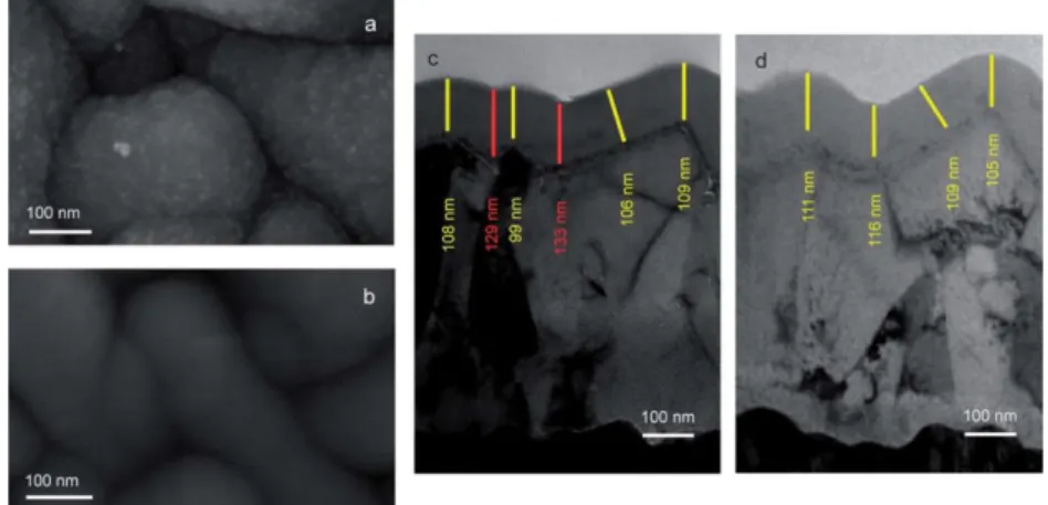
With no clear changes in the crystallinity or the band alignment of the TiO2 overlayer, we decided to take a closer look at the morphology. Under the conditions of the steam treatment (water vapor under pressure), the surface of the TiO2 will undergo continuous modification due to the repeated cleavage and condensation of Ti–O–Ti bonds in lesser-strained forms (surface relaxation). This bond modification is usually associated with a smoothing of the surface.22–24 Fig.
7 shows the surface morphology of the TiO2 overlayer prior to and after steam treatment. It is clear that a morphological change has occurred. Prior to treatment the TiO2 reveals a significant roughness with a grainy structure whereas the steam treatment gave a much smoother surface. The thickness profile of the TiO2 protective layer was also studied by cross-sectional TEM. Different thicknesses of the TiO2 layer were measured along the surface and a clear trend was identified. In agreement with a previous literature report, the thickness of the TiO2 on top of underlayer grain boundaries is larger and at the grain tips is smaller.25 Before steam treatment,
at the Cu2O grain boundaries (represented in red in Fig. 7c) the TiO2 is thicker than at the grain
tips with an average difference of 26 nm. After steam treatment the thickness is much more equally distributed with a thickness standard deviation = 3 nm.
This smoothing process likely patches any defects and cracks in the TiO2 surface as well as improves the quality of the surface for more homogeneous catalyst deposition. In our system, electrodeposition consists of the formation of a layer on a conducting substrate occurring through the electrochemical reduction of higher valence ions dissolved in a suitable aqueous solvent. As electrons flow through the substrate they are transferred to the ions in solution near the surface promoting their reduction and precipitation to form a film. When the substrate is a conducting metal (resistivity on the order of 10-9 m), electrons flow easily to the surface and
are readily available to assist electrodeposition evenly across the surface. On the other hand, when the substrate is several orders of magnitude less conductive, thickness variations on the order of a few nanometers have a large influence on the potential distribution across the surface, resulting in heterogeneous electrodeposition, as the authors verified in previous reports.26–28 Since TiO2 is not a conductor ( 1–10 m),29 the rough surface of the amorphous
TiO2 creates an irregular current density distribution across the surface, yielding a granular RuOx
co-catalyst structure, typical in non-uniform electrodeposition (Fig. S4a†). As the surface turns smooth, the current distribution becomes more regular and the co-catalyst is more homogeneous (Fig. S4b†). Homogeneous deposition of the catalyst on the surface ensures that injected photoelectrons in the TiO2 will be efficiently extracted, thus minimizing the likelihood of electron trapping in the overlayer. Also, the smoothing and healing of small cracks in the overlayer prevent direct contact of the electrolyte with the Cu2O layer, greatly increasing the
stability of the system.
The surface morphology of the photocathode is again modified upon deposition of the RuOx (Fig.
8) offering a higher surface area than the smooth TiO2 layer, which is a clear advantage for catalysis. We have also studied the morphology of the catalyst after a long term stability measurement. After 20 h under continuous illumination conditions, it appears that the catalyst has undergone a large morphological change, by becoming pasty and cracked (Fig. 8e and f). It appears that under extended hydrogen evolution conditions, the surface continues to rearrange and smoothen. The cracks that are observed in the SEM images likely occur only after drying in the high vacuum conditions of the SEM.
To support our theory regarding homogeneous electrode-position, we tested a Pt co-catalyst. Pt is expected to be less stable than RuOx, as previous results indicated,13 but we expected that
and therefore increase stability. A comparison between both catalysts is rep-resented in Fig. 9. We observed an onset potential of +0.64 VRHE and a plateau photocurrent of greater than
5.5 mA cm-2 at 0 V
RHE (Fig. 9a). With a plateau photocurrent 10% greater than that for RuOx and
a significant shift in the onset, this represents a major step forward for unbiased photoelectrochemical tandem systems. The stability of both catalysts is presented in Fig. 9b and c. As expected, the Pt was less stable than the RuOx catalyst, yet is vastly superior to previous
photocathodes that employed Pt catalyst. With 10% loss after 20 h stability measurement biased at 0 VRHE in the pH 5.0 phosphate–sulfate electrolyte under light chopping, this level of stability
represents an improvement of 2000% over previous results.12
Fig. 6 Mott–Schottky plot of TiO2 films prepared using hydrogen peroxide precursor on FTO, measured in 1 M NaOH electrolyte. Steam conditions were 150 oC for 3 h.
Fig. 7 Surface morphology of the TiO2 overlayer (left) and TEM cross-section (right) of an as prepared sample (a and c) and a sample with steam treatment at 150 oC for 3 h (b and d). It is clear that the surface experienced major morphological changes upon steam treatment.
Fig. 8 SEM top view (a and b) of TiO2 after steam treatment at 150 oC for 3 h; (c and d) photo-assisted electrodeposited RuOx catalyst; (e and f) active area after 20 h under illumination conditions.
Table 2 Comparison of electrical properties of the TiO2 films with/ without steam treatment. Flatband and donor density extracted according to the Mott–Schottky equation19
Conclusions
A simple low-cost solution was developed to greatly enhance the Cu2O photocathode stability.
Steam treatments employed on Cu2O/AZO/TiO2 photocathodes allow for stability improvement
using both RuOx and Pt co-catalysts. Not only did we obtain record breaking stabilities in both
cases, we also uncovered the critical importance of morphological changes of the surface in generating these high-stability photocathodes.
Acknowledgements
J. Azevedo, P. Dias and C. T. Sousa are grateful to the FCT SFRH/BD/79207/2011 PhD grant, SFRH/BD/81016/2011 PhD grant and postdoctoral grant SFRH/BPD/82010/2011, respectively. We also acknowledge the FCT through the project H2Solar (PTDC/EQU-EQU/104217/2008). M. Ste k acknowledges startup funds from the University of South Carolina. J. P. Ara´ujo acknowledges NORTE-070124-FEDER-000070 Multifunctional Nanomaterials funded by FEDER and CCDRN. L. Steier, M. Graetzel and S. D. Tilley gratefully acknowledge the Swiss Federal Office for Energy (PECHouse Competence Center, contract number SI/500090–02), the PECDEMO project (co-funded by Europe's Fuel Cell and Hydrogen Joint Undertaking under Grant Agreement no. 621252), and the PHOCS project (European Union, ENERGY 2012-10.2.1, Future Emerging Technologies Collaborative Project no. 309223) for the nancial support. M. Graetzel thanks the European Research Council for the nancial support under the Advanced Research Grant (ARG 247404) “Mesolight.” Additionally, we thank the Interdisciplinary Centre for Electron Microscopy (CIME) and in particular Dr Duncan Alexander for helping with the HR-TEM analysis.
References
1. J. Turner, Science, 1999, 285, 687–689.
2. A. Fujishima and K. Honda, Nature, 1972, 238, 37–38. 3. P. J. Boddy, J. Electrochem. Soc., 1968, 115, 199–203.
4. K. Sivula, F. Le Formal and M. Gratzel, ChemSusChem, 2011, 4, 432–449. 5. C.-Y. Lin, Y.-H. Lai, D. Mersch and E. Reisner, Chem. Sci., 2012, 3, 3482. 6. L. Wang, C.-Y. Lee and P. Schmuki, J. Mater. Chem. A, 2012, 1, 212.
9. F. F. Abdi, L. Han, A. H. M. Smets, M. Zeman, B. Dam and R. van de Krol, Nat. Commun., 2013, 4, 1–18.
10. S. W. Boettcher, E. L. Warren, M. C. Putnam, E. A. Santori, D. Turner-Evans, M. D. Kelzenberg, M. G. Walter, J. R. McKone, B. S. Brunschwig, H. A. Atwater and N. S. Lewis, J. Am. Chem. Soc., 2011, 133, 1216–1219.
11. A. Paracchino, V. Laporte, K. Sivula, M. Gratzel and E. Thimsen, Nat. Mater., 2011, 10, 456– 461.
12. A. Paracchino, N. Mathews, T. Hisatomi, M. S. D. Tilley and M. Gratzel, Energy Environ. Sci., 2012, 5, 8673.
13. S. D. Tilley, M. Schreier, J. Azevedo, M. and M. Graetzel, Adv. Funct. Mater., 2014, 24, 303–311.
14. E. R. K¨otz and S. Stucki, J. Appl. Electrochem., 1987, 17, 1190–1197.
15. A. Paracchino, J. C. Brauer, J.-E. Moser, E. Thimsen and M. Graetzel, J. Phys. Chem. C, 2012, 116, 7341–7350.
16. R. T. Downs and M. Hall-Wallace, Am. Mineral., 2003, 88, 247–250.
17. W. F. Zhang, Y. L. He, M. S. Zhang, Z. Yin and Q. Chen, J. Phys. D: Appl. Phys., 2000, 33, 912–916. 18. H. Solache-Carranco, G. Juarez-Diaz, M. Galvan-Arellano, J. Martinez-Juarez, R.
Romero-Paredes and R. Pena-Sierra, presented at 5th International Conference on Electrical Engineering, Computing Science and Automatic Control, 2008, 421–424.
19. G. Morales-Guio, S. D. Tilley, H. Vrubel, M. Gratzel and X. Hu, Nat. Commun., 2014, 5, 3059. 20. M. Reiners, K. Xu, N. Aslam, A. Devi, R. Waser and Hoffmann-Eifert, Chem. Mater., 2013,
25, 2934–2943.
21. Park, B. L. Clark, D. A. Keszler, J. P. Bender, J. F. Wager, A. Reynolds and G. S. Herman, Science, 2002, 297, 65–65.
22. D. R. G. Mitchell, G. Triani and Z. Zhang, Thin Solid Films, 2008, 516, 8414–8423.
23. A. I. Kontos, I. M. Arabatzis, D. S. Tsoukleris, A. G. Kontos, M. C. Bernard, D. E. Petrakis and P. Falaras, Catal. Today, 2005, 101, 275–281.
24. O. Lupan and T. Pauport´e, J. Cryst. Growth, 2010, 312, 2454–2458.
25. K. Murakami, M. Rommel, B. Hudec, A. Rosov´a, K. Huˇsekov´a, E. Dobroˇcka, R. Rammula, A. Kasikov, J. H. Han, W. Lee, S. J. Song, A. Paskaleva, A. J. Bauer, L. Frey, K. Fr¨ohlich, J. Aarik and C. S. Hwang, ACS Appl. Mater. Interfaces, 2014, 6, 2486–2492.
26. J. Azevedo, C. T. Sousa, J. Ventura, A. Apolin´ario, M. Mendes and J. P. Araujo, Mater. Res. Express, 2014, 1, 015028.
27. J. Azevedo, C. T. Sousa, A. M. Mendes and J. P. Araujo, J. Nanosci. Nanotechnol., 2012, 12, 9112– 9117.
28. T. Sousa, D. C. Leitao, M. P. Proença, A. Apolin´ario, J. G. Correia, J. Ventura and J. P. Araujo,
Nanotechnology, 2011, 22, 315602–315607.