Acknowledgments
First of all, I would like to thank the Erasmus Mundus program and the University of Minho for accepting me as a mobility student. It was a wonderful opportunity, full of new friends and experiences.
I would also like to thank the Engineering of Computer Networks and Telematics Services (MERSTel) program committee members for their help and contribution to my professional growth.
A special appreciation and thanks to my supervisors, Professor Paulo Carvalho and Eng. Emanuel Lima for all of their guidance and encouragements throughout the dissertation process.
Finally, I would like to thank my family for all of their love and support. I know it was hard, but it was worth it.
Abstract
Wireless sensors networks consist of large numbers of small, battery-powered, self-organizing computing motes. Nowadays, these networks are considered ideal candidates for a wide range of applications such as environmental monitoring, military operations and other application fields where it is hard to maintain a continuous presence of human beings.
Online remote reprogramming is usually carried out to update the code running on nodes due to factors such as changes in the environment or application. Remote reprogramming might be applied to the whole network or just to a subset of nodes (selective reprogramming), either way it is crucial to provide reliability for such procedure. Therefore, most of the approaches oriented to remote reprogramming resort to flooding the whole network, leading to a major waste of energy in network nodes.
When dealing with selective reprogramming, the waste of energy increases steeply even when just a small number of nodes need to get the update messages. These messages may be received and retransmitted from all nodes in the network resulting in a waste of resources.
This research identifies multiple scenarios for selective reprogramming and proposes a different energy-aware approach for each one trying to reduce energy consumption in the network by taking advantage of multiple and complementary solutions such as wise routing, clustering and the ability to manage nodes sleeping time instead of using the typical flooding approach.
These approaches were tested and compared with typical flooding and Deluge solutions. The results show a significant reduction of the power consumption, thus, making the selective remote reprogramming more energy-efficient.
Contents List
Acknowledgments ... III Abstract ... IV Contents List ……….……...………...…. V Figures List ... VII Acronyms List ... VIII
1. Introduction ... 1
1.1 Introduction ... 1
1.2 Motivations and objectives ... 2
1.3 Contribution ... 2
1.4 Dissertation structure ... 3
2. Wireless Sensor Network ... 4
2.1 Wireless sensor network characteristics and constraints ... 4
2.2 Wireless sensor node topologies and paradigm ...5
2.3 WSN applications ... 6 2.3.1 Terrestrial applications ... 6 2.3.2 Underground application ... 7 2.3.3 Underwater application ... 7 2.3.4 Multimedia application ... 8 2.3.5 Mobile applications ... 9 2.4 Summary ... 9 3. Energy Issues in WSN... 10
3.1 Sensor node types and architecture ... 10
3.2 Sensor node power supply ... 12
3.3 Power consumption evaluation inside the sensor node ... 13
3.4 WSN energy consumption due network traffic ... 15
3.5 Power conservation mechanisms ... 16
3.5.1 Radio optimization ... 17
3.5.2 Data aggregation ... 18
4. WSN Remote Reprogramming ... 23
4.1 Remote reprogramming in wireless sensor network ... 23
4.2 Remote reprogramming challenges ... 24
4.3 Energy consumption sources in reprogramming process ... 25
4.4 Remote reprogramming protocols ... 25
4.4.1 Reliable remote reprograming protocols ... 26
4.4.2 Fast remote reprogramming protocols ... 27
4.4.3 Energy-efficient remote reprogramming protocols ... 28
4.5 Selective Remote reprogramming protocols ... 31
4.6 Summary ... 32
5. Strategies to enhance selective reprogramming ... 33
5.1 Revisiting selective reprogramming within Deluge ... 33
5.2 Selective reprogramming using the BS ... 35
5.3 Selective reprogramming using updated nodes ... 37
5.3.1 Selective reprogramming with clustering ... 37
5.3.2 Selective reprogramming in flat networks ... 40
5.4 Summary ... 40
6. Strategies implementation and simulation results ... 41
6.1 Results on selective reprogramming using the BS ... 41
6.2 Results on selective reprogramming using updated nodes ... 45
6.3 Summary ... 48
7. Conclusions and future work ... 49
Figures List
Fig 2. 1: WSN topologies [4] 6
Fig 2. 2: Underwater wireless sensor network [27] 8
Fig 3. 1: Sensor node main component [33] 11
Fig 3. 2: Cluster-based aggregation. 19
Fig 3. 3: Energy as routing metric. 20
Fig 3. 4: Multipath routing. 21
Fig 5. 1: Structure of DE and DF packets [3]. 34
Fig 5. 2: DE packet modified structure. 34
Fig 5. 3: Disseminating the code from the BS to the selected node. 35
Fig 5. 4: CP and BP messages structure. 36
Fig 5. 5: Code dissemination in a WSN with clustering. 38
Fig 5. 6: Info message and SOS message structure. 39
Fig 6. 1: Selective reprogramming using BS scenario. 42
Fig 6. 2: Messages sent and received at SN. 43
Fig 6. 3: Messages sent and received at NPN. 44
Fig 6. 4: Messages sent and received at PN. 44
Fig 6. 5: Selective reprogramming using updated nodes scenario. 46
Fig 6. 6: The cluster structure in the simulation scenario. 46
Fig 6. 7: Messages sent and received at SN. 47
Acronyms List
BP Best Path
BPN Bit Per Node
BS Base Station
CH Cluster Head
CN Cluster Node
CP Check Path
DCFR Double Cost Function based Route
EECDA Energy-Efficient Clustering and Data Aggregation Protocol EEMRP Energy-Efficient Multipath Routing Protocol
EEORP Energy-Efficient Online Reprogramming Protocol ESCFR Exponential and Sine Cost Function based Route
HEED Hybrid, Energy-Efficient, Distributed clustering approach LEACH Low-Energy, Adaptive Clustering Hierarchy
MCU Micro-Control Unit
MEMS Micro-Electro-Mechanical Systems
MNP Multihop Network Reprogramming
MOAP Multihop Over-the-Air Programming
NOH Number Of Hops
NPN Non-Path Node
PEGASIS Power-Efficient Gathering in Sensor Information Systems
PN Path Node
SASA Structure-Aware Self-Adaptive SEP Stable Election Protocol
SN Selected Node
SOS Sleep Or Send
TDMA Time Division Multiple Access
TTS Time To Sleep
UW-sensor Under Water sensor
WUSN Wireless Underground Sensor Network
1. Introduction
1.1 Introduction
Wireless Sensor Networks (WSNs) are networks of tiny, battery powered sensor nodes with limited on-board processing, storage and radio capabilities [1]. Nodes sense and send their reports toward a processing center called “sink”.
WSNs have gained worldwide attention in recent years, particularly with the proliferation in Micro-Electro-Mechanical Systems (MEMS) technology, which has facilitated the development of small sized, smart sensors. These sensors are inexpensive compared to traditional sensors and can operate for extended periods of time without physical intervention by humans [2].
Due to the potential to provide fine-grained sensing and actuation at a reasonable cost, these networks are considered ideal candidates for a wide range of applications such as industrial monitoring and military operations.
Program image updates, may also be referred to as code image or software updates, have become a requirement for long-lived networks due to changes in the functionality of the software running on the nodes, software updates, and security enhancements or for bug fixing after WSNs have been deployed. However, if WSNs are large scale or deployed in a harsh environment, it is impossible to reprogram manually all nodes. Online network reprogramming can remotely reprogram all nodes via wireless communication. Hence it becomes a promising technique [3].
Most proposed remote reprogramming protocols in WSNs take advantage of wireless nodes using dissemination strategies to reach all network nodes (remote reprogramming for the whole network). In some cases, just a few number of nodes might need to be reprogrammed (selective reprogramming). Either way, it is crucial to provide reliability for such procedure. However, for large WSNs, where the sink cannot reach every node through single-hop communication, updates can only be transmitted using multi-hop approaches, which normally consumes a significant amount of energy in the nodes and thus reducing the network lifetime.
When dealing with selective reprogramming, the waste of energy is magnified since only a small number of nodes needs to get update messages, while these messages might be received and retransmitted from all nodes resulting in a waste of resources.
The main goal for this research is to make selective reprogramming of WSNs as efficient as possible, reducing the energy consumption in the network while maintaining the reliability and versatility required for such procedure.
1.2 Motivations and objectives
Energy constrain is considered one of the main challenges facing wireless sensor networks(WSNs) since most sensor nodes still use battery as the main source of power.
Radio activities such as messages transmission/reception and idle listening are considered major factors of energy consumption in motes. These activities increase with the increase of reliability level required, hence it is usually achieved by broadcasting and rebroadcasting. Procedures such as remote reprogramming require high level of reliability leading to an increase in radio activities in the network, thus, more waste of energy. This waste increases steeply when dealing with selective reprogramming where only few nodes need to receive the code updates while most approaches used are dependent on flooding the whole network forcing all nodes to receive the code.
The main objective of this research is to study and optimize energy consumption in selective remote reprogramming procedure, presenting multiple scenarios and proposing a different approach for each to perform this procedure in an energy efficient way while trying to maintain reliability needed for this process.
The performance metrics we are focusing on the number of messages received and transmitted which is directly related to energy consumption in the nodes.
1.3 Contribution
Our contributions in this work consists of presenting multiple scenarios for selective reprogramming and propose a different approach for each, trying to reduce energy consumption in the network. We do this by taking advantage of multiple and complementary solutions such as wise routing, clustering and the ability to manage nodes sleeping time instead of using the typical flooding approach. In this thesis, we also propose an enhancement to Deluge extension for selective reprogramming in WSNs [4] in order to reduce the overhead in the reprogramming packets used in this protocol, thus, minimizing the number of packets needed.
We will consider two possibilities when performing selective reprogramming of a WSN depending on the centrality of the new code image to be disseminated. A first possibility is that the program image resides only in the base station and a specific node needs to be reprogrammed. In this scenario, flooding the whole network with code messages should be avoided, thus, we will try sending the code from the base station to the selected node following the path with the highest energy levels, while forcing other nodes outside this path to turn their radios off.
A second possibility is that when some of nodes deployed in the network already have the updated code image that needs to be routed to the selected node. In this case, two other scenarios need to be discussed. The first one is when the network has some sort of hierarchy in place, for instance, via node clustering. In this case, we suggest the use of multiple senders instead of only one to perform code dissemination. Thus, each sender can contribute by sending a number of code messages according to its residual energy. The other scenario is when the network is flat, i.e., with no hierarchy, and multiple nodes within vicinity to the selected node can play the role of sender.
1.4 Dissertation structure
This chapter describes the structure of the dissertation. Chapter 2 provides an overview of wireless sensors network, their characteristics, constrains, topologies and applications. Chapter 3 discusses energy issues in WSNs, including energy consumption and saving.
Chapter 4 focuses on remote reprogramming in WSNs, the challenges facing this procedure and the protocols proposed to do a whole or selective reprogramming.
Chapter 5 presents various scenarios of selective remote reprogramming and the suggested strategies to perform this procedure in an energy efficient manner.
Chapter 6 describes the proposed strategies implementation and the simulation results.
2. Wireless Sensor Network
This chapter presents a general overview of wireless sensor networks and is organized as followed: in section 2, some WSN characteristics and constraints are identified, section 3 describes the WSN topologies and paradigm. Finally, WSN applications are presented in section 4.
2.1 Wireless sensor network characteristics and
constraints
A wireless sensor network (WSN) is a network made up of a large number of small sensors called sensor node or mote. This network, in general, also has one or several stations (sink) to put the data collected from the small sensors [5].
By providing fine-grained and unintrusive monitoring in real-time, WSNs allow tight integration of the physical world with a computing system infrastructure. WSNs have been demonstrated to play an important role in a rich variety of applications such as environmental and civilian infrastructure monitoring [6], wildlife tracking [7], military surveillance, etc.
Sensor nodes are able to capture various physical information such as barometric pressure, ambient temperature, atmospheric humidity, wind direction, wind speed, underground water level, and rainfall. The collaborative nature of sensor nodes brings several advantages over traditional sensing including greater fault tolerance, improved accuracy, large coverage area and extraction of localized features [8]. However, sensor nodes are usually battery-powered and deployed in a harsh or hostile environment where it is very difficult or even impossible to change or recharge the batteries [9]. Therefore, power consumption is a central design consideration in wireless sensor networks. However, since various sensor nodes often detect common phenomena, there is likely to be some redundancy in the data the various sources communicate to a particular sink so in-network filtering and processing techniques can help to conserve the scarce energy resources [10]. Sensor nodes are also highly limited in computation and storage capacities [9].
A WSN is usually designed and deployed for a specific application. The design requirements of a network change with its application. Hence the nodes are prone to physical damages or failures, and in addition to the dynamic environmental conditions require the system to adapt over time to change connectivity and system stimuli [11, 12].
No global identification is available for WSNs due to the large number of sensor nodes which makes impossible to build a global addressing scheme for a sensor network since it would introduce a high overhead for the identification [9, 12].
In most sensor network applications, the data sensed by sensor nodes flow from multiple source sensor nodes to a particular sink, exhibiting a many-to-one traffic pattern.
Sensors may be deployed in an ad hoc manner into the field then left unattended to perform monitoring and reporting functions. In an unstructured WSN, network maintenance is difficult since there might be so many nodes requiring that the system identifies and copes with the failure and connectivity loss between the nodes that it is necessary providing some automatic configuration and reconfiguration support (self-configuration) [11,13].
Security challenges in WSN are at many levels [13]. From the system point of view, it is critical that the information provided by the nodes be authenticated and the integrity verified, since this information provides the feedback loop to expensive equipment controlling power consumption depends on app. From the users’ point of view, it is also critical that this information cannot be easily spoofed remaining protected in the back end processor, since it may affect the privacy of users.
2.2 Wireless sensor node topologies and paradigm
The most common four WSN data network topologies are Peer to Peer (also called Point to Point), Star, Tree and Mesh [14].
Peer-to-Peer networks allow each node to communicate directly with
another node without needing to go through a centralized communications hub.
Star topology needs a central hub where all communications must be routed
through it. Each node is then a “client” while the central hub is the “server”. The central hub is shown in Fig 2.1. Tree networks use a central node called a Root node as the main communications router. One level down from the Root node in the hierarchy is a Central hub. This lower level then forms a Star network. The Tree network can be considered a hybrid of both the Star and Peer-to-Peer networking topologies. Usually most routing protocols in WSNs are based on cluster tree topology where all cluster members route their data to a cluster head.
Mesh networks allow data to “hop” from node to node which allows the network
to be self-healing. Each node is then able to communicate with each other as data is routed from node to node until it reaches the desired location [14]. Fig 2.1 illustrates the different topologies in WSN.
Fig 2. 1: WSN topologies [4]
Data aggregation is considered the essential paradigm for routing in
sensor networks [15, 16]. The idea is to combine the data coming from different sources enroute, eliminating redundancy and minimizing the number of transmissions, thus saving energy. This paradigm shifts the focus from the traditional address-centric approaches for networking (finding short routes between pairs of addressable end-nodes) to a more data-centric approach (finding routes from multiple sources to a single destination that allows in-network consolidation of redundant data) [10]. The topologies used when applying data aggregation on WSN are usually the cluster and the tree topologies.
2.3 WSN applications
Wireless sensor networks (WSNs) have enabled numerous embedded wireless applications in different areas, such as military/battlefield, environmental monitoring, and intelligent building systems [17]. The following subsections will present some of WSNs applications.
2.3.1 Terrestrial applications
In this type of applications, hundreds to thousands of inexpensive wireless sensor nodes are deployed in a given area, either in an ad hoc or in a pre-planned manner. In ad hoc deployment, sensor nodes can be dropped from a plane and randomly placed into the target area [13].
In [18], a WSN was used for battlefield surveillance where the network was able to detect and classify multiple targets (e.g., vehicles and troop
movements) using inexpensive sensor capable of sensing acoustic and magnetic signals generated by different target objects. In [19], a real-time wireless physiological monitoring system for nursing centers was implemented. Its function is to monitor online the physiological status of aged patients via wireless communication channel and wired local area network. The collected data, such as body temperature, blood pressure, and heart rate, can then be stored in the computer of a network management center to facilitate the medical staff in a nursing center to monitor in real time or analyze in batch mode the physiological changes of the patients under observation. Other projects related to healthcare are [20] [21].
Environmental monitoring is carried out in [22] where a wireless sensor network is deployed on Great Duck Island, Maine. These networks monitor the microclimates in and around nesting burrows used by the Leach's Storm Petrel.
2.3.2 Underground application
Wireless Underground Sensor Network (WUSN) can be used to monitor a variety of conditions, such as soil properties for agricultural applications and toxic substances for environmental monitoring, Sensors are also successfully used to monitor the integrity of belowground infrastructures such as plumbing, landslide and earthquake monitoring are accomplished using buried seismometers [23]. In [24], a Structure-Aware Self-Adaptive sensor system, SASA, is presented with the aim to address the challenges and provide a feasible framework for underground monitoring in coal mines. The design objectives of SASA are: i) rapidly detect the collapse area and report to the sink node; and ii) maintain the system integrity when the sensor network structure is altered.
There have been several works on tunnel monitoring such as [25] where the author proposes to utilize electro level systems to measure the structural variations in London underground tunnels.
2.3.3 Underwater application
Underwater WSNs consist of a number of underwater sensor nodes (UW-sensors) and vehicles deployed underwater. As opposite to terrestrial WSNs, underwater sensor nodes are more expensive and fewer sensor nodes are deployed. Autonomous underwater vehicles are used for exploration or gathering data from sensor nodes. Compared to a dense deployment of sensor nodes in a terrestrial WSN, a sparse deployment of sensor nodes is placed underwater. Typical underwater wireless communications are established through transmission of acoustic waves [26]. Fig 2.2 illustrates an underwater wireless sensor network.
Fig 2. 2: Underwater wireless sensor network [27]
A promising application for underwater sensor networks is seismic monitoring for oil extraction from underwater fields. Frequent seismic monitoring is of importance in oil extraction. Studies of variation in the reservoir over time are called “4-D seismic” and are useful for judging field performance and motivating intervention.
Underwater equipment monitoring is a second example application. Long-term equipment monitoring may be done with pre-installed infrastructure. However, temporary monitoring would benefit from low-power, wireless communication.
A third underwater application for WSN is supporting groups of underwater autonomous robots. Applications include coordinating adaptive sensing of chemical leaks or biological phenomena (for example, oil leaks or phytoplankton concentrations) [28].
Multimedia WSNs consist of a number of low cost sensor nodes equipped with cameras and microphones such as Panoptes [29], which is a system developed for environmental observation and surveillance applications, based on Intel StrongARM PDA platforms with a Logitech webcam as a video capture device.
In [30], a system whose objective is to limit the computation, bandwidth, and human attention burdens imposed by large-scale video surveillance systems is described. In-network processing is used on each camera to filter out uninteresting events locally, avoiding disambiguation and tracking of irrelevant environmental distractors.
2.3.5 Mobile applications
Mobile applications use sensor nodes that can move on their own and interact with the physical environment. A key difference is that mobile nodes have the ability to reposition and organize themselves in the network. A mobile WSN can start off with some initial deployment and nodes can then spread out to gather information. Information gathered by a mobile node can be communicated to another mobile node when they are within range of each other.
Other key difference is data distribution. In a static WSN, data can be distributed using fixed routing or flooding while dynamic routing is used in a mobile WSN. Challenges in a mobile WSN include deployment, localization, self-organization, navigation and control, coverage, energy, maintenance, and data process [13].
2.4 Summary
In this chapter, some WSN characteristics, topologies and applications were discussed.
As it has been highlighted in this chapter, WSN can be deployed in harsh environments where continuous presence of humans is impossible. Therefore, reducing energy consumption in WSN is a central design consideration since sensor nodes are usually battery-powered.
In the following chapter, power consumption in wireless sensor networks will be discussed thoroughly. After, the mechanisms used to save energy in WSN will be presented.
3. Energy Issues in WSN
This chapter will focus on the following issues: sensor nodes’ types and architecture, sensor power sources, energy consumption and energy saving in
WSNs. This will follow as sections.
3.1 Sensor node types and architecture
A sensor node, also known as a mote, is a node in a sensor network that is capable of performing some processing, gathering sensory information and communicating with other connected nodes in the network. A wireless sensor network (WSN) consists of spatially distributed autonomous motes to monitor physical or environmental conditions. Depending on the sensor nodes within the network, WSNs can be categorized into heterogeneous and homogeneous networks. Heterogeneous WSN consists of sensor nodes with different ability, such as different computing power and sensing range, whereas homogeneous WSN consists of identical sensor nodes [31].
There are many types of sensor nodes. The application where the wireless sensor network is applied is what determines what type of sensors to use. Some sensors can sense physical properties such as pressure, humidity, temperature, and flow. Other sensors can measure motion properties like position, velocity, angular velocity, and acceleration. Some sensors can measure proximity, distance, range, etc. A single sensor node might be able to sense several environmental metrics. Sensor nodes can also be classified based on their mobility to static and mobile nodes, or based on their capabilities to super nodes and low end nodes.
A typical sensor node usually consists of four sub-systems [32], as illustrated in Fig 3.1. These subsystems are:
a) A computing subsystem
Consists of RAM, flash memories, and a microprocessor that typically uses a set of analog-to-digital converters (ADCs) to obtain data from sensors and communications protocols [33]. The microprocessor can operate under various operating modes for power management purposes. However, shuttling between these operating modes involves consumption of power, so the energy consumption levels of the various modes should be considered while looking at the battery lifetime of each node [32]. This subsystem can also be referred to as Micro-Control Unit (MCU).
b) A communication subsystem
Consists of a short range radio which is used to communicate with neighboring nodes and the outside world. Radios can operate under the Transmit, Receive, Idle and Sleep modes. It is important to completely shut down the radio rather than put it in idle mode when it is not transmitting or receiving because of the high power consumed in this mode [32]. This subsystem can also be referred to as Micro Control Unit (MCU).
c) A sensing subsystem
Consists of a group of sensors and actuators that link the node to the outside world. Energy consumption can be reduced by using low power components and saving power at the cost of performance which is not required [32].
d) A power supply subsystem
Consists typically of two AA batteries. Expected lifetimes of batteries should range from months to years in wireless sensor network applications since it is undesirable to recharge or replace the batteries of thousands of sensor nodes frequently. When a node is depleted of energy, it can no longer fulfill its role unless the source of energy is replenished. Therefore, it is generally accepted that the usefulness of a wireless sensor (or wireless sensor node) expires when its battery runs out [17].
The amount of power drawn from a battery should be checked because if a high current is drawn from a battery for a long time, the battery will die even though it could have gone on for a longer time. The lifetime of a battery can be increased by reducing the current drastically or even turning it off often [32]. These components are illustrated in Fig 3.1
3.2 Sensor node power supply
Power is a scarce resource in WSNs. As an example, the capacity of the
Smart Dust mote is 33mAh [34] as powered by a single size- 5 hearing aid
battery. For MicaZ and Mica2 nodes [34], which use two AA batteries, the node capacity is limited to 1400–3400 mAh. Similarly, the recent SunSPOT platform uses a 750mAh lithium-ion battery [36].
Batteries continue to be the leading power source for sensor nodes. However, it is also possible to extend the lifetime of the WSNs through energy scavenging [37, 38], which is extracting energy from the environment. Solar cells offer excellent power density in direct sunlight. However, in dim office lighting, or areas with no light, they are inadequate. Power scavenged from thermal gradients is also considered. Nevertheless, it is difficult to find greater than a 10 0C1 thermal gradient in a volume of 1 cm3. Starner [39] has documented, that there is ample power to scavenge from the human body. Fuel cells also represent a potentially large improvement over batteries as an energy reservoir. Research to miniaturize fuel cells is currently underway [40]. Miniaturized fuel cells could extend the lifetime of a node up to several times when compared to battery-powered sources, and so would either require re-fueling, or would have a limited lifetime.
It should be noted that while the energy density of hydrocarbon fuels used in micro heat engines is very high, the output power of these devices is too high (on the order of 1–10 W) to be of practical use for low power wireless sensor nodes [41]. Furthermore, once started, they are not easily turned off. Their use would therefore necessitate a large energy storage reservoir to allow for lower power operation over a longer lifetime, thus negating their advantage.
As stated, non-rechargeable batteries remain the main source used for powering wireless nodes because of their higher energy densities, lower leakage rates and cost. For sensor node applications, battery lifetimes of at least a year are desirable, corresponding to 32 J per μW average power. Lithium based primary batteries provide 1400 – 3600 J/cc [42], so in principle a lifetime of several years is achievable for a battery well below 1 cc [43].
3.3 Power consumption evaluation inside the
sensor node
First we must analyze and estimate power consumption characteristics of a wireless sensor node to be able to optimize and control energy consumption.
There are several methods to estimate the power consumption of a WSN node, including theoretical estimation, direct measurements, and the usage of simulations tools [44]. The best way to carry out the power consumption evaluation is directly on the physical hardware, by periodically measuring the remaining battery. This will provide a precise evaluation for power consumption, but it is very costly, tedious and may be unfeasible considering the (usual) large number of WSN nodes. Furthermore, due to the inherent dynamism of WSNs, the instrumentation required by measurement techniques makes difficult their use in several different scenarios [45].
The simulation of energy-aware WSNs using currently available tools has a number of shortcomings. First, most available simulators lack adequate support for the node’s hardware (especially energy sources such as photovoltaic and vibration harvesters) and the needed environmental models (available environmental models are often too inflexible to allow easy integration of new hardware). Second, the node’s simulated embedded hardware is structured largely around communications, giving little consideration to the implementation and interfacing of sensor processing and energy-aware algorithms [46]. One of the simulators used to evaluate energy in WSN is PowerTOSSIM [47], which has been built on top of TOSSIM simulator to estimate Mica2’s energy consumption. Another widely used simulator is Avrora [48] which can simulate AVR-based microcontroller MICA2 sensor nodes, and supports energy consumption simulation. However, this simulator has several drawbacks. Avrora does not have GUI and it cannot simulate network management algorithms because it does not provide network communication tools. There is also eSimu, which is a software module that implements platform specific energy consumption models, and provides an estimation of the current absorbed by a node [49].
Recent analyses of WSN energy efficiency have been widely based on sensor node power consumption models [50] [51]. Such models may be analytically evaluated and/or simulated. Although modeling may provide less accurate results than measuring, it provides the designers the flexibility and agility to evaluate complex scenarios without interfering on the actual environment [45].
Power consumption in the node is distributed among the node’s subsystems mentioned: MCU, communication subsystem, battery and the
sensing unit. While power consumption can be considered static or neglected in the sensing unit and battery, MCU and communication subsystem have a significant effect on the node’s energy consumption characteristics.
The MCU used in the node is usually chosen based on the required performance levels and the node’s power consumption characteristics. For example, the StrongARM microprocessor from Intel, used in high-end sensor nodes, consumes around 400 mW of power while executing instructions, whereas the ATmega103L AVR microcontroller from Atmel consumes only around 16.5 mW, but provides much lower performance. Thus, the choice of MCU should be dictated by the application scenario, to achieve a close match between the performance level offered by the MCU and that demanded by the application. Further, MCUs usually support various operating modes, including Active, Idle, and Sleep modes, for power management purposes. Each mode is characterized by a different amount of power consumption [52].
Power consumption measurements of the communication subsystem in sensor node devices reveal clear discrepancies between the widely cited power consumption models and the actual characteristics of real hardware implementations. For example, the measured power consumption of the receiving circuitry is often greater than the power consumption of the transmitting circuitry [53] [54] [55]. Similarly, the power consumption for baseband digital signal processing is found to be comparable to the power consumption of the combined transmit and receive circuitry [56].
A classical energy consumption model has been proposed by Heinzelman
et. al based on the observation that the energy consumption would likely be
dominated by the data communications subsystem [57]. Table 3.1 summarizes their consumption model.
Radio mode Energy Consumption
Transmitter Electronics
Receiver Electronics 50 nJ/bit
Transmit Amplifier 100 pJ/bit/m2
Idle 40 nJ/bit
Sleep 0
Table 3.1: The classical energy consumption model
This model has not been verified against the behavior of a physical radio in a wireless sensor network.
Shih et. Al [58] presented energy model developed for a specific platform, the μAMPS Wireless Sensor Node. The platform has a StrongARM SA 1110
microprocessor with a clock speed from 59 Mhz to 206 Mhz. The model takes into consideration the energy consumed by the microcontroller, the energy lost due to leakage and the average consumption of the radio [58]. Table 3.2 summarizes the model characteristics.
State SA-1110 Sensor A/D Radio Pk (mW)
Active Active Sense Tx/rx 1040
Ready Idle Sense Rx 400
Monitor Sleep Sense Rx 270
Observe Sleep Sense Off 200
Deep Sleep Sleep Off Off 10
Table 3.2: Energy consumption model of μAMPS
The μAMPS model does not specify the power consumed in transmitting or receiving one bit. Nonetheless, the platform uses transmission rate of 1 Mbps, so the energies required for transmitting and receiving one bit can be calculated as follows:
Time to send or receive one bit = 1 / 1 Mbps = 1 μsec
Energy = Power * Time (**) where Power is in Watts and Time is in seconds.
Replacing the time value and the values taken from the table in the equation (**), it is possible to find the energy required to transmit one bit as followed:
Energy
Txonebit = 1040 * 1 *10
-3
W * 1 *10-6 sec= 1.04 μJ/bit Repeating the same method, we find:
Energy
RxonebitReadystate = 0.4 μJ/bit
Energy
RxonebitMonitorstate = 0.27 μJ/bit
In the present research work, we are going to benefit from modeling to evaluate the energy consumption in the sensor nodes. The corresponding process will be detailed in chapter 6.
3.4 WSN energy consumption due network traffic
In the previous sections, we discussed the main causes of energy consumption inside the sensor node. It is concluded that the transceiver unit is considered the main contributor to energy waste. Therefore, any additional network traffic or activities that affect this unit will lead to additional energy consumption. This section will present in-network activities that affect energy
consumption in WSN. Later, the mechanisms used to contradict this affect and to save energy in the network will be discussed in section 3.5.
The different sources of energy waste that are related to network traffic can be classified into: idle listening, collisions, overhearing, and overhead. These categories are discussed in more details below [59] [60].
a) Idle Listening
Occurs when a node listens to the channel for a possible reception, but nothing is received. Idle listening has been identified as the major source of energy waste in a sensor node, mainly due to the low traffic loads commonly found in WSNs.
b) Collisions
When two (or more) nodes transmit simultaneously, the recipient may be unable to decode any of the packets involved. This problem implies that the senders waste energy through transmitting and that the receiver expends energy receiving without obtaining any benefit, as senders may eventually retry transmission. In the presence of hidden terminals, this effect is even more important because transmitters cannot sense each other.
c) Overhearing
This source of energy waste occurs when a sensor node wastes energy receiving a packet that is intended for a different destination.
d) Overhead
Data packets in WSNs are usually small; therefore, headers and other types of overhead (such as control messages) imply a high-level of energy waste for WSNs.
3.5 Power conservation mechanisms
Energy consumption reduction in WSN has attracted the interest of both the academic and the industrial worlds. The next subsections are devoted to present the mechanisms exploited to reduce energy consumption in WSNs.
Mechanisms used to reduce energy consumption in WSNs can be categorized into two main categories: passive mechanisms, and active mechanisms.
Passive power conservation mechanisms reduce the energy consumption of a sensor node by turning off its transceiver interface module when there is no communication activity [61]. Additional energy savings can be achieved by
optimizing the performance of the processor in an active state changing its operational frequency [62].
Active power conservation mechanisms differ from passive ones in that they achieve a reduction of the energy consumption by avoiding undesired events such as collision. For instance, adjusting the transmission power may help minimizing the probability of occurrence of a collision, an event that leads to higher power consumption due to the related detection and retransmission activities [44]. Energy-aware routing protocols are also exploited to reduce energy consumption in WSNs. Some researchers [63] have claimed that multi-hop network implementations consume less energy than an equivalent single-multi-hop network. Conversely, other researchers [64, 65, 66] argue that single-hop implementations consume less energy in relaying data compared to equivalent multi-hop networks due to simpler routing protocols, lower communication overhead, and higher overall efficiency.
There is still much ongoing research on how to optimize power usage in battery-limited sensor networks. However, none of the proposed solutions is universally applicable. The main idea in energy-efficient mechanisms is to avoid the causes of energy waste such as idle listening, overhearing, and overhead.
We will focus on the power saving mechanisms which will be used in our approaches. These mechanisms are: (i) radio optimization; (ii) data aggregation; and (iii) energy-efficient routing, detailed in the following subsections.
3.5.1 Radio optimization
Since the radio module is considered the main component that causes battery depletion, researchers have tried to reduce energy waste due to wireless communication by optimizing radio parameters such as coding and modulation schemes, transmission power and antenna direction [67].
Idle states are major sources of energy consumption at the radio component. Sleep/wakeup schemes aim to adapt node activity to save energy by putting the radio in sleep mode for as much time as possible since sleep mode consumes substantially less energy than the other available modes (idle, transmitting or receiving). In sleep mode, a sensor node is not able to receive/transmit packets from/to the medium. This solution greatly reduces the idle listening energy waste. However, specific mechanisms should be defined to ensure that a sensor node will be awake if a node sends something to it [59].
The sleep/wakeup schemes can be categorized into: a) Duty cycling
schemes which schedule the node radio state depending on network activity in
usually divided into three categories: on-demand, asynchronous, and scheduled
rendezvous. In the on-demand approach, the node wakes up only when other
node wants to communicate with it. In the asynchronous approach, the node wakes up at the same time as its neighbors according to a wakeup schedule then the nodes go to sleep until their next rendezvous. Finally, in the scheduled rendezvous, the node wakes up independently but its active period must overlap with its neighbors [68].
Duty-cycle based protocols are certainly the most energy-efficient but they suffer from sleep latency because a node must wait for the receiver to be awake. Moreover, in some cases it is not possible for a node to broadcast information to all of its neighbors because they are not active simultaneously [67]. b) Passive
wake-up radios: where power radios are used to awake a node only when it
needs to receive or transmit packets while a power-hungry radio is used for data transmission. Such approach is used in [69]. c) Topology control: when sensors are redundantly deployed in order to ensure good space coverage, it is possible to deactivate some nodes while maintaining network operations and connectivity. In such approach, nodes that are not necessary for ensuring connectivity or coverage can be turned off in order to prolong the network lifetime. In [70], this approach is used to save energy in the network and to prolong its lifetime.
3.5.2 Data aggregation
Data aggregation has been put forward as an essential paradigm for
wireless routing in sensor networks. The idea is to combine the data coming from different sources eliminating redundancy, minimizing the number of transmissions and thus saving energy. This paradigm shifts the focus from the traditional address-centric approaches for networking (finding short routes between pairs of addressable end-nodes) to a more data-centric approach (finding routes from multiple sources to a single destination that allows in-network consolidation of redundant data) [71].
Data aggregation includes the following three approaches:
a) Tree-based approach
This approach performs aggregation by constructing an aggregation tree, which could be a minimum spanning tree, rooted at sink and considering source nodes as leaves. Each node has a parent node to forward its data. Flow of data starts from leaf nodes up to the sink and therein the aggregation is carried out by parent nodes [72].
The key idea behind chain-based data aggregation is that each sensor only
transmits to its closest neighbor. This procedure continuous till the data reaches the sink or the base station [73]. PEGASIS protocol [74] uses this approach.
c) Cluster-based approach
In the cluster-based approach, as illustrated in Fig 3.2, the whole network
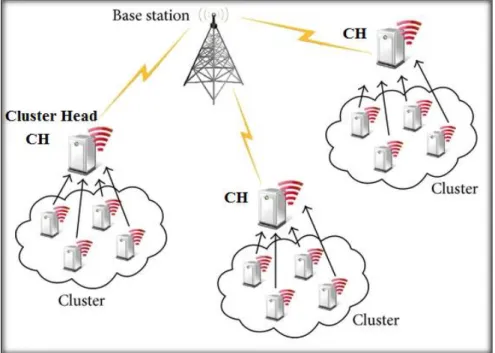
is divided into several clusters. Each cluster has a cluster-head (CH), which is selected among cluster members. Cluster-heads do the role of aggregator, which consists of aggregating the data received from cluster members locally and then transmitting the result to the sink. The cluster approach is considered a special case of the tree approach [75]. This approach was adopted in many protocols such as LEACH [76], HEED [77], TEEN [78], EECDA [79], and SEP [80].
Cluster techniques have been proposed to enhance energy efficiency because they help to limit energy consumption via different means: (i) reducing the communication range inside the cluster ,thus, requiring less transmission power, (ii) limiting the number of transmissions thanks to fusion performed by the CH, (iii) reducing energy-intensive operations such as coordination and aggregation to the cluster head, (iv) providing the ability to power-off some nodes inside the cluster while the CH takes forwarding responsibilities; and (v) balancing energy consumption among nodes via CH rotation. In addition to energy-efficiency, cluster architectures also improve network scalability by maintaining a hierarchy in the network [81] [82].
Routing can seriously drain nodes’ energy. In particular, in multi-hop schemes, nodes closer to the sink have to route more packets. Therefore, their battery depletes faster. In what follows, we discuss some energy-saving mechanisms of different routing paradigms.
a) Energy as a routing metric
A solution proposed to extend the lifetime of sensor networks is to consider energy as a metric in the setup path phase. By doing so, routing algorithms do not only focus on the shortest paths but can select the next-hop based on its residual energy as shown in Fig 3.3. Recently, Liu et al. [83] introduced two new energy-aware cost functions. The Exponential and Sine Cost Function based Route (ESCFR) function can map a small change in the remaining nodal energy to a large change in the cost function value. By giving preference to sensors with higher levels of remaining energy during route selection, the function enforces energy balance. The Double Cost Function based Route (DCFR) protocol considers the energy consumption rate of nodes in addition to their remaining energy.
Fig 3. 3: Energy as routing metric
Multipath routing enables energy to be balanced among nodes by alternating the forwarding nodes. As an example, the EEMRP (Energy-Efficient Multipath Routing Protocol) [84] discovers multiple node-disjoint paths using a cost function depending on the energy levels and hop distances of the nodes and allocates the traffic rate to each selected path. The EECA (Energy-Efficient and Collision Aware) protocol [85] constructs two node-disjoint and collision-free routes between a source and a sink. Multipath routing protocols also enhance network reliability by providing multiple routes, which enables the network to recover faster from a failure, whereas in single path schemes when a node runs out of power, a new route must be recomputed. Multipath routing is illustrated in Fig3.4.
Fig 3. 4: Multipath routing
c) Relay node placement
The premature depletion of nodes in a given region can partition the network or create energy holes. Sometimes, this situation can be avoided thanks to the optimal placement of nodes through an even distribution or by adding a few relay nodes with enhanced capabilities. This helps to improve energy balance between nodes, avoid sensor hotspots and ensure coverage and connectivity [86].
Several works have focused on finding the minimum number of relay nodes or placing them optimally to prolong the network lifetime [87] [88].
d) Sink mobility
Most of the traffic in the sensor network is forwarded towards a sink, which increases the workload of the nodes closer to the sink. Thus, these nodes become hotspots and consume their energy quickly. The hotspot problem causes an early rupture of the network because the hotspot nodes no longer relay data for the farther nodes when they run out of their energy [89].
To increase network lifetime, it is possible to balance the load between nodes using a mobile base station, which moves around the network to collect node information. Sink mobility also improves connectivity in sparse architectures and enhances reliability because communication occurs in a single-hop fashion. Thus, it reduces contention, collisions and message loss [90]. When controllable, this mobile displacement can be studied to prevent high latency, buffer overflow and energy depletion [91, 92]. However, the sink mobility approach can create different problems. For example, in applications that gather data periodically, the purpose of employing a mobile sink is usually to improve flexibility and prolong network lifetime while gathering sensed data timely, reliably and efficiently. However, the sink cannot move in a random way, which is energy-unconscious and only a little beneficial to balancing energy consumption [93, 94]. Furthermore, a mobile sink that moves along fixed tracks [95-98] lacks flexibility and scalability because its moving path has to be redesigned for different networks. Autonomous moving schemes, in which a sink makes moving decisions according to the circumstances at that time, can provide reasonable adaptability to various types of network conditions.
3.6 Summary
In this chapter, we presented, sensor node’s architecture, the power consumption sources inside the node and in the network, the methods adopted to estimate energy consumption in the node, and the different techniques proposed to save energy in WSN. These techniques, including radio optimization, data aggregation, and energy-efficient routing were discussed in detail.
In our attempt to make selective remote reprogramming as energy-efficient as possible, these three methods will be used. In the following chapter, remote reprogramming challenges and protocols will be discussed thoroughly to precede the explanation of the strategies proposed here to reduce power consumption in the selective remote reprogramming process.
4. WSN Remote Reprogramming
After deploying the network nodes, and as a result of change in the environment or in the application, it might be necessary to update the code running on sensor boards or to distribute management commands to sensors. However, due to the harsh hazards of the environments where these networks are deployed, it might be impossible to reprogram these nodes manually. Therefore, online or remote reprogramming is suggested as the best solution to achieve such modifications on the nodes [99]. Remote reprogramming might be applied to the whole network or just to subset of nodes (selective reprogramming), either way, it is crucial to provide reliability for such procedure. Therefore, most of the approaches proposed to perform remote reprogramming resort to flooding the whole network, leading to a major waste of energy in each node.
When dealing with selective reprogramming, the waste of energy increases steeply since only a small number of nodes need to get the update messages, while these messages might be received and retransmitted from all nodes resulting in a waste of resources.
As mentioned in Chapter 1, the present research aims to conserve energy as much as possible while performing selective reprogramming. Therefore, this chapter will discuss online remote reprogramming (RR) and selective remote reprogramming (SRR), the challenges and requirements that these procedures should satisfy, and the currently used protocols with their advantages and disadvantages.
4.1 Remote reprogramming in wireless sensor
network
Software update research is a key topic in wireless sensor networks. The need to update the update mechanism itself, to reconfigure parameters, and to provide users with standardized features to manage online changes have also been identified, along with the need for overall update management [99].
The first step in reprogramming a sensor node is to decide when reprogramming is needed and which part of the code needs updating. This can be decided and initiated by the system user, or automatically (in a distributed manner) by the nodes themselves. In the former case, the system user issues a reprogramming command along with a set of attributes and the nodes operate in a slave-like mode. In the latter, the nodes should realize whether a code update is needed on their own. Coming to the second case, a straightforward solution
would be to periodically announce a profile of the code they run, so that their neighbors can compare the received information with the current version of the code to figure out whether a code update is needed or not [100].
Most remote reprogramming protocols are based on an algorithm named Trickle [101], which uses “polite gossip” to exchange code metadata with nearby network neighbors. Trickle breaks time into intervals, and at a random point in each interval, it considers broadcasting its code metadata. If Trickle has already heard several other motes gossip the same metadata in this interval, it politely stays quiet: repeating what someone else has said is rude. When a mote hears that a neighbor is behind the times (it hears older metadata), it brings everyone nearby up to date by broadcasting the needed pieces of code. When a mote hears that it is behind the times, it repeats the latest news that is aware of (its own metadata), following the first rule, this triggers motes with newer code to broadcast it [101].
4.2 Remote reprogramming challenges
The main challenge in remote reprogramming is that it requires reliable delivery. This involves two requirements: every node in the network must receive the program code, and it must be received in its entirety. This is very different from traditional sensor network applications, in which, occasional loss of data is tolerable [102]. High communication bandwidth is also needed in network reprogramming. For the vast majority of sensor network applications, the generated sensing data from an individual sensor node is small, usually of the order of bytes, and thus easily fits the low wireless radio bandwidth. However, delivering the entire program image, of the order of kilobytes over low-bandwidth wireless radio, as required in network reprogramming, requires significant bandwidth [102].
The problem of concurrent senders might appear in remote reprogramming because every node that has the new code image is a potential sender. Thus, it is likely that too many senders are transmitting at the same time, causing collisions, congestion and possibly failure of reprogramming. Energy consumption is also considered a problem due to sensor nodes power supply limitation, therefore, the amount of energy consumed during the reprogramming process may directly affect network lifetime [102].
Additionally, a reprogramming protocol must take into consideration the large amount of data needed to be transferred compared to the memory available on the node [100], and the time required to distribute the data for
reprogramming should be minimized [100]. Sufficient support for incremental upgrades should also be provided since program data often evolves slowly [100].
4.3 Energy consumption sources in
reprogramming process
Several key factors affect reprogramming process efficiency and reprogramming lifetime of a WSN, including the transferred code size, the loading cost, and the reprogramming voltage requirement [103]. First, the transferred code size greatly impacts on transmission overhead. For example, to make a WSN reprogrammable, Deluge [2] disseminates the entire program image, including the application code, the TinyOS kernel, and the reprogramming protocol. Second, the loading cost for executing the new code needs to be minimized. In particular, hardware reboot should be avoided as it wastes energy as well as dropping data. A system normally stores many state data such as routing tables [104], synchronization tables [105], dissemination keys, etc. After rebooting, some nodes may take hours to fully come back online. Third, it is beneficial to avoid flash writes during reprogramming as writing to flash requires a much higher voltage than the minimum operational voltage commonly used, for instance, in TelosB nodes [103].
There are also other factors that affect energy consumption without being particularly related to the reprogramming process such as idle listening (which is a major source of energy waste [106]), message collision, overhearing, control message overhead and the number of messages sent and received.
4.4 Remote reprogramming protocols
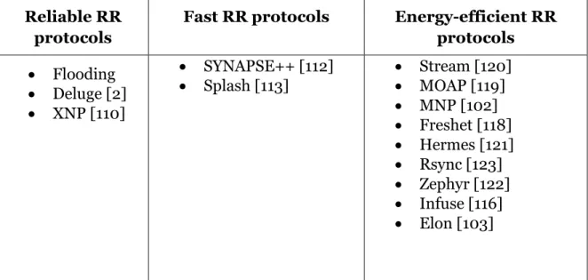
A large number of remote reprogramming protocols have been proposed recently. Depending on their main focus, these protocols can be classified as reliable protocols, fast protocols or energy-efficient protocols. The protocols these categories encompass are illustrated in Table 4.1, and discussed in the following subsections.
Reliable RR protocols
Fast RR protocols Energy-efficient RR protocols
Reliable RR protocols
Fast RR protocols Energy-efficient RR protocols
Flooding Deluge [2] XNP [110]
SYNAPSE++ [112]
Splash [113] Stream [120] MOAP [119] MNP [102] Freshet [118] Hermes [121] Rsync [123] Zephyr [122] Infuse [116] Elon [103]
Table 4.1: Remote reprogramming protocol categories
4.4.1 Reliable remote reprograming protocols
Many remote reprogramming approaches were proposed having reliability of code dissemination as their main concern, depending heavily on broadcasting to achieve that and leading to solutions that still evince limitations regarding energy efficiency.
A straightforward example of these protocols is classic flooding: a base node broadcasts new codes to its neighbors. Upon receiving the data, each node stores it and then rebroadcasts to its neighbors. However, in dense large-scale WSNs with limited energy, classic flooding is particularly costly resulting in serious redundancy, contention, and collision. This is called the “broadcast storm” problem [107], and it is mainly caused by two deficiencies: data redundancy and sender redundancy where some senders are redundant to cover a desired area [108].
Deluge [1] is also considered one of the main reliable protocols available but with no consideration for energy efficiency. It is a NACK-based protocol that relies on periodic advertisements to keep nodes informed of their neighbors' states; it uses a three-stage handshake protocol consisting of advertisement, request and data, where updated nodes advertise their code version and outdated nodes will request these nodes for the new code image. Deluge [1] provides high reliability, robustness and support for multi-hop network reprogramming while being simple to implement. However, it requires radio to be always on causing nodes to be in idle listening mode during the reprogramming process. This leads to a considerable amount of energy waste since idle listening is one of the major
sources of energy consumption in WSNs[2]. It also suffers from the hidden terminal problem [109], which occurs when two senders out of range of each other transmit packets to the same receiver at the same time, thus causing collisions at the receiver.
Broadcasting is also used extensively in XNP protocol [110]. To distribute the program image in XNP, the source broadcasts the entire image and then queries nodes for the lost packets. Nodes make requests if necessary. The source then rebroadcasts every packet requested by some node, allowing other nodes to snoop and fill their own missing slots [2]. This guarantees the delivery of the program image (the default code distribution scheme in TinyOS). The problem in XNP is that it only operates over a single hop and does not provide incremental updates of the code image [3]; it also requires all nodes to be within bidirectional communication range of the source [2].
Although these protocols guarantee one hundred percent reliability, they fail to accomplish reprogramming process in energy-efficient manner.
4.4.2 Fast remote reprogramming protocols
This type of protocols usually uses a mechanism called pipelining to reduce reprogramming completion time. In this mechanism, the code image is divided into several segments. A segment consists of many packets. The packet is the transferred object. Dividing code image aims to conserve memory needed to maintain the received data in the node and to allow the use of spatial multiplexing. Spatial multiplexing is the most important issue here, as it affects the completion time. In spatial multiplexing, different segments can be transferred simultaneously. These parallel transmissions lead to shorter completion time [111].
An example of fast reprogramming protocols is SYNAPSE++ protocol [112], which reduces reprogramming completion time significantly using an original pipelining strategy, coupled with a novel and distributed channel access mechanism called soft Time Division Multiple Access (soft TDMA). The authors improved the Fountain Code (FC) implementation of SYNAPSE by a joint design with the forwarding mechanism in order to maximize the number of errors that are corrected through overhearing, thus limiting the number of explicit retransmissions. SYNAPSE++ [112] features advanced boot loader and memory management modules, which allow the dissemination of binary images written in any operating system and make application and reprogramming software completely independent in terms of memory and variables. This protocol reduces the time required for reprogramming significantly. Pipelining is also used in Splash [113], which is scalable to large, multi-hop sensor networks and built upon
two recent works: Glossy [114] and PIP [115]. Splash eliminates the need for contention resolution by exploiting constructive interference and channel diversity to effectively create fast and parallel pipelines over multiple paths that cover all the nodes in a network. This is called tree pipelining. In order to ensure high reliability, Splash also incorporates several techniques, including exploiting transmission density diversity, opportunistic overhearing, channel-cycling and XOR coding. Evaluation results showed that Splash is faster than state-of-art dissemination protocols and achieves a reduction in data dissemination time by a factor of more than 20 compared to DelugeT2.
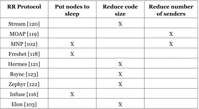
4.4.3 Energy-efficient remote reprogramming
protocols
As discussed in the previous chapter, the mechanisms usually used to save energy in WSN are: radio optimization, data aggregation and energy-efficient routing. Most energy-efficient remote reprogramming protocols rely mainly on radio optimization to conserve energy. The techniques used are: putting nodes to sleep, reducing the size of transferred code or reducing the number of senders. For example, Infuse [116] takes advantage of turning off node’s radio to reduce energy consumption. It disseminates data in TDMA slots assigned to each sensor. To recover from lost messages, implicit acknowledgments (received by listening to the transmissions of the successors of a sensor) are used. The authors presented two possible recovery algorithms based on modified sliding window protocols to use implicit acknowledgments. Infuse [116] recovers from random message losses caused by varying link properties and message corruption. It disseminates data in an energy-efficient manner reducing the number of message transmissions and receptions. Since Infuse uses a TDMA-based MAC protocol, sensors only need to listen to the radio in the slots assigned to their neighbors. In the remaining slots, sensors can turn off their radio. The main disadvantage of Infuse is that the two recovery algorithms the authors present have weaknesses. The first one (Go-Back-N) has a critical window size that must be satisfied, otherwise the latency will be increased. In the second recovery algorithm (Selective retransmission), the authors observed that the dissemination latency increases considerably in the presence of failed sensors [116].
Putting nodes to sleep to save energy is also used in MNP [102]. This protocol also tries to reduce power consumption by reducing the number of senders. The sender selection algorithm attempts to guarantee that in a neighborhood there is at most one source transmitting the program at a time. Furthermore, the sender selection process is greedy as it tries to select the sender that is expected to have the most impact. It also uses pipelining to enable fast data propagation. MNP [102] reduces collisions, the hidden terminal problem
![Fig 2. 1: WSN topologies [4]](https://thumb-eu.123doks.com/thumbv2/123dok_br/17564533.817656/14.918.140.784.150.423/fig-wsn-topologies.webp)
![Fig 2. 2: Underwater wireless sensor network [27]](https://thumb-eu.123doks.com/thumbv2/123dok_br/17564533.817656/16.918.144.778.131.606/fig-underwater-wireless-sensor-network.webp)
![Fig 3. 1: Sensor node main component [33]](https://thumb-eu.123doks.com/thumbv2/123dok_br/17564533.817656/19.918.238.679.791.1006/fig-sensor-node-main-component.webp)


![Fig 5. 1: Structure of DE and DF packets [3].](https://thumb-eu.123doks.com/thumbv2/123dok_br/17564533.817656/42.918.252.662.266.486/fig-structure-df-packets.webp)
