Laser-glazing of plasma-sprayed thermal barrier coatings : experimental and computational studies
41
0
0
Texto
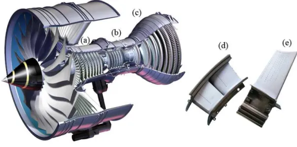
(2) Chapter 1. Thermal Barrier Coatings (TBCs) – State of the Art. Fig. 1.1. Illustration of a gas turbine engine: (a) compressor, (b) combustor and (c) turbine sections. (d) Vanes and (e) blades are some of the components of the turbine section which require a TBC.. The application of TBCs is driven by technological and economic aspects such as increase of the turbine thermal efficiency due to higher turbine temperatures, increase of the compressor efficiency due to a reduced air flow for the turbine cooling, longer service life of metallic turbine components due to a decreased thermal fatigue [6]. The increase of a gas turbine efficiency can be obtained through heat transfer and aerodynamic analysis and improvements in coating materials and processing conditions [7]. The last point is the one in which this thesis is focused.. 2. Historical background. The early work on TBC development relating to gas turbine engines started at the beginning of 1950s [7]. At that time gas temperatures, pressures, and heat fluxes which were relatively low compared to the engines of nowadays [8-10]. A great part of the early TBC research was conducted at the National Aeronautics and Space Administration (NASA∗), Lewis Research ∗. The National Advisory Committee for Aeronautics (NACA) was established in 1915, and became the National Aeronautics and Space Administration (NASA) on October 1, 1958.. 2.
(3) Chapter 1. Thermal Barrier Coatings (TBCs) – State of the Art. Center, USA, and was focused on the thermal and corrosion protection of uncooled or air-cooled gas turbine blades and to water or fuel-cooled rocket engine walls. Experiments in which silicon dioxide or boric oxide were studied on turbine blades during engine operation showed a negligible effect on the measured blade temperatures and deteriorated after several hours of engine operation [9]. Other attempts to apply TBCs to turbine hardware by enameling or glazing processes are reported. The coatings also spalled and cracked after several hours of testing [8]. The use of TBCs in rocket engines which generated much higher heat fluxes resulted in considerable thermal protection but with poor durability [11]. The coating systems investigated were thin layers of molybdenum, nichrome, tungsten, alumina, zirconia, and chromia and were all either plasma-sprayed or slurry coated and cured in place. Of the early ceramic materials, alumina and zirconia-calcia were the most successful. The bond coat material, if one was used at all, was typically nichrome or molybdenum for nonoxidizing environments. Alumina and zirconia-calcia did not prove to be viable materials for the more advanced thermal barrier applications. In the case of alumina, the reason is that the thermal conductivity is relatively high [12]. Moreover, alumina forms nonequilibrium phases, which are referred to as gamma, eta, or delta. These nonequilibrium phases shrink when they convert to the equilibrium alpha phase upon high temperature exposure. This shrinkage and the associated cracking would have a detrimental effect on coating life. The problem with zirconiacalcia and zirconia-magnesia is related to destabilization from the cubic fluorite phase to the monoclinic phase. Zirconia-based ceramics containing excessive amounts of this monoclinic phase are not usable as structural materials due to the volume change associated with a martensitic phase transformation on cooling from the higher temperature tetragonal phase to the low-temperature monoclinic phase. The structural characteristics and phase stability of the various polymorphs of zirconia will be described later on this thesis. It was only during the 1970s that the reliability of using TBCs in modern gas turbines has been demonstrated. A major advance in this field was the successful completion of tests conducted by Liebert [13], where the significant heat insulating capability of thin TBCs was experimentally demonstrated. The results showed that a 280m thick coating of ZrO2-12wt%Y2O3 over a 100µm thick coating of NiCrAlY provided a reduction of 190ºC in the substrate temperature. This TBC represented a breakthrough in the thermal barrier coating technology and its success was due to the three novel approaches: (1) yttria was used to stabilize the zirconia. 3.
(4) Chapter 1. Thermal Barrier Coatings (TBCs) – State of the Art. rather than calcia or magnesia; (2) a NiCrAlY alloy was used as bond coat rather than nichrome; and (3) the coating system was applied in two thin layers rather than three [14, 15]. Subsequent experiments in more advanced and higher heat flux gas turbine engines showed that although this TBC system was very promising its durability at high gas temperatures and pressures would have to be improved [16]. Later on, TBCs with increased durability have been developed through adjustments in bond coat composition [17, 18], ceramic composition [19] and plasma-spray parameters [20]. The initial zirconia-yttria TBCs contained 12 to 20% of yttria, which was added to fully stabilize the cubic phase. Later, Stecura showed that better performance could be achieved by lowering the yttria level to between 6 and 8% [19].. 3. Current state of the art 3.1. Conventional thermal barrier coatings. The development of today’s gas turbine engines has been the result of continual improvements in a wide variety of engineering skills including turbine design, combustion, and materials. One measure of the substantial improvements over the past five decades is the increase in the maximum gas temperature at a turbine airfoil afforded by these improvements. The increase in airfoil temperature has been facilitated by three principal materials developments: dramatic advances in alloy design to produce alloy compositions that are both more creep resistant and oxidation resistant; advances in casting technology that have facilitated not only the casting of large single-crystal superalloy blades and vanes but also the complex internal channels in the blades to facilitate cooling; and the development of a viable coating technology to deposit a conformal, thermally insulating coating on turbine components. Less well known is the development of thermal barrier coatings (TBCs), even though in the last decade their use has enabled a dramatic increase in airfoil temperature, far greater than that enabled by the switch from cast alloy blades to single crystal blades over approximately 30 years [21]. The selection of TBC materials is restricted by some basic requirements such as high melting point, no phase transformation between room temperature and operation temperature, low thermal conductivity, chemical inertness, thermal expansion match with the metallic substrate, good adherence to the metallic substrate and low sintering rate of the porous microstructure [22].. 4.
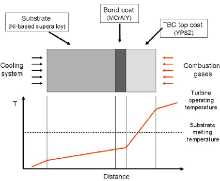
(5) Chapter 1. Thermal Barrier Coatings (TBCs) – State of the Art. The current TBC system, as illustrated in Fig. 1.2, consists of four layers:. (1) a metal substrate providing structural strength; (2) a bond coat providing oxidation resistance; (3) a thermally grown oxide (TGO) formed between the ceramic top coat and the bond coat due to high temperature oxidation of the bond coat; (4) an external ceramic top coat providing the thermal insulation.. Fig. 1.2. Schematic diagram of a conventional thermal barrier coating system (top) in service and the exemplificative thermal gradients in the different regions (bottom).. (1) Substrate. Gas turbine engines make use of nickel and cobalt base superalloys in the turbine components, such as airfoils, combustors, transition ducts, and seals [3]. The nickel or cobaltbased structural superalloy is the substrate material, which is air-cooled from the inside or through internal hollow channels, therefore establishing a temperature gradient across the component wall. The superalloy component is investment-cast in single-crystal or polycrystalline forms, and it contains as many as 5 to 12 additional elements that are added for the. 5.
(6) Chapter 1. Thermal Barrier Coatings (TBCs) – State of the Art. improvement of specific properties such as high-temperature strength, ductility, oxidation resistance, hot-corrosion resistance, and castability [2]. At the high temperature of operation in gas-turbine engines, diffusion of elements of high relative concentration can occur between the superalloy substrate and the bond-coat. These diffusing elements can occasionally be found in the TGO and the top-coat as well. This interdiffusion can have a great influence on the spallation failure of the TBC, making it necessary to treat thermal barrier—coated superalloys as an engineering system whose properties change with time and cycles during service.. (2) Bond-coat and (3) thermally grown oxide (TGO) The bond-coat is a 75 to 150 µm thick oxidation-resistant metallic layer, and it essentially dictates the spallation failure of the TBC. The bond-coat is typically made of a NiCrAIY or NiCoCrAIY alloy and is deposited by using the plasma-spray or the electron-beam physical-vapor deposition methods. Other types of bond-coats are made of aluminides of Ni and Pt and are deposited by electroplating in conjunction with diffusion-aluminizing or chemical-vapor deposition. In a minority of cases, the bond-coat consists of more than one layer, having a different chemical/phase composition. At peak operating conditions the bond-coat temperature in gasturbine engines typically exceeds 700°C, resulting in bond-coat oxidation and the inevitable formation of a third layer—the thermally grown oxide (TGO; 1 to 10 µm in thickness) — between the bond-coat and the ceramic top-coat [23]. The interconnected porosity that always exists in the top-coat allows easy ingress of oxygen from the engine environment to the bond-coat. Moreover, even if the top-coat were fully dense, the extremely high ionic diffusivity of oxygen in the ZrO2based ceramic top-coat makes it “transparent” to oxygen [24]. Although the formation of the TGO is unavoidable, the ideal bond-coat is engineered to ensure that the TGO forms as α-AI2O3 and that its growth is slow, uniform, and free from defects. The TGO has a very low oxygen ionic diffusivity and provides an excellent diffusion barrier, retarding further bond-coat oxidation [25]. Generally, the internal diffusion of oxygen through the TGO controls further growth of TGO into the bond-coat, but in some cases TGO growth is controlled by external diffusion of Al, leading to the formation of the new TGO at the TGO/top-coat interface or at the α-Al2O3 grain boundaries within the TGO. At last, the bondcoat composition is designed to obtain a highly adherent TGO [26]. It is known that the segregation of S at the bond-coat/TGO interface reduces the TGO adhesion dramatically [27]. To reduce this. 6.
(7) Chapter 1. Thermal Barrier Coatings (TBCs) – State of the Art. undesirable effect of S, either the S content in the bond-coat is maintained below 1 ppm or S gettering reactive elements (Y, Zr) are added [28]. Other elements that degrade the bondcoat/TGO adhesion, Ti and Ta, are also kept below acceptable levels in the bond-coat, whereas elements that promote adhesion, Si and Hf. are added in small quantities [29].. (4) Ceramic top-coat. This is the layer that provides the thermal insulation and is typically made of Y2O3-stabilized ZrO2 (YSZ) [30]. YSZ has a set of desirable properties that makes it the material of choice for the topcoat. It has one of the lowest thermal conductivities at elevated temperature of all ceramics (∼2.3 W/mK at 1000°C for a fully dense material [31]) because of its high concentration of point defects (oxygen vacancies and substitutional solute atoms), which scatter heat-conducting phonons (lattice waves) [32, 33]. YSZ also has a high thermal-expansion coefficient (∼11×10-6 °C1. ), which helps to relieve the stresses generated from the thermal-expansion mismatch between. the ceramic top-coat and the underlying metal (~14 ×10-6 °C-1). To further relieve these stresses, microstructural features such as cracks and porosity are deliberately engineered the top-coat, making it highly compliant (elastic modulus ~50 GPa) and strain tolerant. YSZ has a relatively low density (~6.4 gcm-3), which is important for parasitic-weight considerations in rotating engine components. It also has a hardness of ~14 GPa, which makes it resistant to erosion and foreignbody impact. YSZ is resistant to ambient and hot corrosion. Finally, YSZ has a high melting point (~2700°C), making it suitable for high-temperature applications. Although ZrO2 can be stabilized by a host of different oxides (MgO, CeO2, Sc2O3, In2O3, CaO), Y2O3- stabilized ZrO2 (YSZ) has been empirically found to be most suitable for TBC applications [34]. YSZ exists as three different polymorphs — monoclinic, tetragonal, and cubic — depending on the composition and the temperature [35]. The addition of 7 to 8 weight % (~4 to 4.5 mol%) Y2O3 stabilizes the t'-phase, the most desirable phase for TBC applications [34]. This is a variation of the tetragonal phase, but unlike its low Y2O3 contents (~3 mol%), the t' phase does not undergo a martensitic transformation and is, therefore, more stable [35].. 7.
(8) Chapter 1. Thermal Barrier Coatings (TBCs) – State of the Art. 3.2. Processing technologies. Today there are two processes used to apply TBCs – Plasma-spraying (PS) and electron beam physical vapor deposition (EB-PVD). Plasma sprayed coatings were brought into service first and still remain. In the 1990s a second type of deposition process was brought into commercial service – physical vapor deposition (PVD).. 3.2.1. Atmospheric Plasma-Sprayed TBCs (APS) The current era in TBCs began in the 70s with the development of a two-layer TBC consisting of a porous atmospheric plasma-sprayed (APS) zirconia-yttria (ZrO2-Y2O3) ceramic over a plasmasprayed NiCrAlY bond coat and with the successful testing of this coating on the turbine blades in a research gas turbine engine [36].. (a). (b) Fig. 1.3. Plasma-spraying equipment [37] and process details: (a) photographs of the deposition process, (b) schematic illustration of the plasma-spraying deposition [38].. 8.
(9) Chapter 1. Thermal Barrier Coatings (TBCs) – State of the Art. Plasma-spraying, one of the thermal spraying family’s processing technologies, is a materials processing technique for producing coatings and free-standing parts using a plasma jet which is produced by an electric discharge in a gas. The plasma-spraying Process is basically the spraying of molten or heat softened material onto a surface to provide a coating (Fig. 1.3). Material in the form of powder is injected into a very high temperature (up to 20000K) plasma jet, where it is rapidly heated and accelerated to a high velocity (~400 m/s). The hot material impacts on the substrate surface and rapidly cools forming a coating.. (a). (b) Fig. 1.4. A typical microstructure of an atmospheric plasma-sprayed TBC: (a) optical micrograph [39], (b) schematic illustration of the splat-like microstructure [40].. Coatings deposited by plasma-spraying are characterized by a relatively good adhesive strength (20 - 70 MPa) and a porosity that can be adjusted for the application in question between 1% to 20%. The characteristics of the TBC are a result of the processing conditions. For. 9.
(10) Chapter 1. Thermal Barrier Coatings (TBCs) – State of the Art. instance, Portinha et al have prepared TBCs with gradient in porosity by changing the processing conditions during deposition [41]. The microstructure of a typical plasma sprayed thermal barrier is illustrated in Fig. 1.4 and can be compared to that produced by EB-PVD, Fig. 1.7. The plasma sprayed coating develops with a ‘splat-like’ morphology and can incorporate between 10–15% porosity as a result of the spraying process. Furthermore, microcracking of the partially stabilised zirconia ceramic occurs during processing. This acts to further reduce the elastic modulus of the ceramic and therefore helps minimise the stresses that can develop, but makes the coating more susceptible to damage by particle impaction. By way of contrast, the EB-PVD ceramic has a columnar microstructure and this accounts for the improved strain tolerance observed for this class of coating. Thus, under mechanical load, or thermal cycling, the ceramic columns produced by the EB-PVD process can move relative to each other as strain cycles are applied to the component. The microstructure of TBCs applied by plasma spraying will be significantly influenced by process parameters and grain size distribution of the ceramic powder. The main processing parameters affecting coating characteristics are substrate roughness, grain size of ceramic powder, gun pressure, type of atmosphere, carrier gas flow rate, spraying distance, powder feed rate, torch speed and cooling of the substrate [42]. Fig. 1.5 shows the typical pore size distribution for a porous and a dense APS TBC system, which has been measured by mercury immersion testing [43]. As it can be observed there are two different types of porosity contribution, microcracks and pores. Using this technique, pores below 0.5 mm can be measured. These small pores cannot be seen by optical microscopy, but make a significant contribution to the overall porosity. The plasma spraying process is most commonly used in normal atmospheric conditions and referred as APS. Some plasma spraying is conducted in protective environments using vacuum chambers normally back filled with a protective gas at low pressure, this is referred as VPS or LPPS. Deposits having thickness from micrometers to several millimeters can be produced from a variety of materials - metals, ceramics, polymers and composites. There are several applications for plasma-spraying in coatings technology namely seal coatings, dimensional correction coatings, wear protection coatings, electrical insulation coatings but one of main application fields of the thermal spraying process is thermal barrier coatings TBCs [44].. 10.
(11) Chapter 1. Fig. 1.5.. Thermal Barrier Coatings (TBCs) – State of the Art. (a) Pore size distribution for a dense and a porous TBC applied by air plasma spraying; (b) Dense TBC, applied by APS; (c) Porous TBC, applied by APS [43].. 3.2.2. Electron beam physical vapour deposited (EB-PVD) TBCs. EB-PVD coatings are particularly suitable when applied on cooled airfoils of front stage vanes and blades. A schematic description of a EB-PVD equipment is shown in Fig. 1.6. Using this deposition process the shape and diameter of cooling holes remains unaffected and the resulting surface roughness is low compared with APS coatings (0.5 to 1 µm average roughness Ra for EBPVD coatings compared with 4 to 10 µm Ra for APS coatings). The main drawback of the EB PVD. 11.
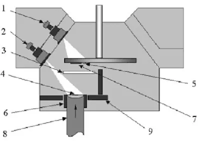
(12) Chapter 1. Thermal Barrier Coatings (TBCs) – State of the Art. process is the high investment cost. Hence there is only a limited amount of equipment available world-wide. The microstructure of EB-PVD TBCs coating is mainly affected by the following deposition parameters [45-47]:. Substrate temperature: This affects surface diffusion of deposited zirconium, yttrium and oxygen, as well as nucleation of stable oxide particles and their growth rate. Surface diffusion and growth rate of oxide particles have a major influence on the TBC microstructure.. Surface roughness of the bond coating: A smooth surface promotes parallel growth of lamellar zirconia. With increasing surface roughness, the width of the lamellae increases, as well as the deviation from ideal orientation.. Rotation rate of the component and vapor flux from the evaporator: To coat complex shaped parts uniformly, rotation and tilting of the components has to be performed during the coating process. The morphology of these microstructures depends on the vapor flux from the evaporation source and the rotation rate. Increasing vapor flux at constant rotation rate results in coarser substructures due to higher condensation rates. Decreasing rotation rates, at constant vapour flux, also promotes coarser substructures.. Fig. 1.6. Schematic diagram of the developed EB-PVD apparatus for coatings production: 1 - electron beam gun for heating the substrate holder; 2 - evaporator gun, 3 - shutter, 4 - molten pool, 5 - thermocouple, 6 crucible, 7 - substrate, 8 - ingot, 9 - water-cooled crucible plate.. 12.
(13) Chapter 1. Thermal Barrier Coatings (TBCs) – State of the Art. The TBC layers produced by EB-PVD have a columnar microstructure (Fig. 1.7) with elongated intercolumnar pores that become predominantly aligned perpendicular to the plane of the coating as its thickness increases [40]. A finer distribution of intracolumnar pores also exists. The elongated intercolumnar pores increase the compliance of the coating in the plane of the substrate, and leads to the improved spallation lifetimes of the TBC.. (a). (b) Fig. 1.7. Typical microstructure of an EB-PVD TBC: : (a) optical micrograph [39], (b) schematic illustration of the columnar microstructure [40].. 4. Ceramic materials for TBCs and properties. In this section, the basic properties of ceramic materials for thermal barrier coatings are summarized. Ceramics, in contrast to metals, are often more resistant to oxidation, corrosion and 13.
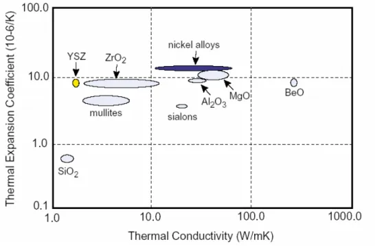
(14) Chapter 1. Thermal Barrier Coatings (TBCs) – State of the Art. wear, as well as being better thermal insulators. Besides yttria stabilized zirconia, other materials such as lanthanum zirconate and rare earth oxides are also promising materials for thermal barrier coatings [48]. Several ceramic coatings such as Al2O3, TiO2, mullite, CaO/MgO+ZrO2, YSZ, CeO2+YSZ, zircon and La2Zr2O7, etc. have been evaluated as TBC materials. Since number of requirements is difficult to meet in a single material, the number of candidates that can be used as TBCs is very limited. So far, only a few materials have been found to basically satisfy these requirements. Properties of some ceramics that can be used in TBC system are summarized in Table 1.1. Among those properties, thermal expansion coefficient and thermal conductivity seem to be the most important. Metal substrate and bond coats are also included for comparison. The number before yttria stabilized zirconia (YSZ) represents the weight percentage of Y2O3 in ZrO2. The advantages and disadvantages of other TBC materials are compared with YSZ and listed in Table 1.2. The improvement techniques of YSZ coatings are also summarized in this table. In Fig. 1.8 is plotted the thermal expansion coefficient versus thermal conductivity of candidate materials for TBCs. As it can be observed YSZ has the best compliance, i.e. a thermal expansion coefficient near that of nickel alloys (substrates) and a very low thermal conductivity.. Fig. 1.8. Thermal expansion coefficient versus thermal conductivity of candidates to be used as TBC.. 14.
(15) Chapter 1. Thermal Barrier Coatings (TBCs) – State of the Art. Table 1.1. Properties of TBC materials [48].. Materials. Properties. ZrO. T = 2973 K D = 0.43x10 m s (1273 K) m. 2. -6. 2. Materials. Properties. La Zr O. Tm = 2573 K D = 0.54x10 m s (1273 K) Cp = 0.49 J g K (1273 K) λ = 1.56 W m K (1273 K) E = 175 GPa (293 K) α = 9.1x10 K (293–1273 K). 2. 2. 7. -1. -6. th. -6. -1. -1. -6. m. -6. 2. BaZrO. -6. -6. -1. -1. E = 40 GPa (293 K) α = 10.7x10 K (293–1273 K) ν = 0.22 -6. (plasmasprayed). p. -1. TiO. T = 2098 K D = 0.52x10 m s (1073 K) m. 2. -1. α = 10.53x10 K (1273 K) -6. -6. 2. -1. -1. 3. 5. 12. -1. T = 2243 K m. α = 9.1x10 K λ = 3.0 W m K (1273 K) -6. -1. -1. 5 wt.% CaO+ZrO. 2. 4. 2. 10. Lanthanum aluminate (LaMgAl O ). λ = 1.7 W m K (1273 K) α = 10.1x10 K (298–1473 K) Cp = 0.86 J g K (1273 K). T = 2123 K. LaPO. T = 2343 K. -1. m. -6. 2. 11. λ = 3.3 W m K (1400 K) E = 30 GPa (293 K) α = 5.3x10 K (293–1273 K) ν = 0.25 -1. Al O. -6. 2. -1. th. λ = 5.8 W m K (1400 K) E = 30 GPa (293 K) α = 9.6x10 K (1273 K) ν = 0.26 -1. -6. 2. 3. Al O +TiO 2. 3. -1. -1. -6. -1. -1. -1. m. λ = 1.8 W m K (973 K) α = 10.5x10 K (1273 K) E = 133 GPa (293 K) ν = 0.28 (293 K) -1. -1. -6. -1. E = 86 GPa (293 K). (bond coat of TBC). α = 17.5x10 K (293–1273 K) ν = 0.3. IN737 supper-alloy. E = 197 GPa (293 K). -6. -1. -1. α = 8x10 K (293–1273 K) ν = 0.22 -1. D =0.65x10 m s (1273 K) -6. 2. NiCoCrAlY. -1. E = 360 GPa (293 K) -6. 4. -1. m. Al O (TGO). 19. -1. T = 2323 K D = 0.47x10 m s (1273 K). 3. -1. Tsoftening=2558 K E = 149.3 GPa (293 K) α = 9.91x10 K (1273 K) ν = 0.28 -6. Mullite (Al Si O ). -1. th. λ = 3.3 W m K (1400 K) E = 283 GPa (293 K) α = 9.4x10 K (293–1500 K) ν = 0.28. Garnet (Y Al O ). -1. -1. -1. -6. 18YSZ. -1. -1. λ = 3.42W m K (1273 K) E = 181 GPa (293 K) α = 8.1x10 K (293–1273 K) -6. 8YSZ. 2. th. λ = 2.12 W m K (1273 K) Cp = 0.64 J g K (1273 K) α = 11.5x10 K (293–1273 K) -1. -1. m. -1. -1. -1. T = 2963 K D = 1.25x10 m s (1273 K) C = 0.45 J g K (1273 K). 3. -1. th. -1. -1. -1. -1. -1. T = 2973 K D = 0.58x10 m s (1273 K). 3YSZ. 2. th. λ = 2.17 W m K (1273 K) E = 21 GPa (1373 K) α = 15.3x10 K (1273 K) ν = 0.25 -1. 2. -1. th. α = 5.56x10 K (1073 K) -6. -1. (Substrate of TBC). α = 16x10 K (293–1273 K) ν = 0.3. CeO. T = 2873 K D = 0.86x10 m s (1273 K) C = 0.47 J g K (1273 K). 2. -6. -1. m. -6. 2. -1. th. -1. -1. p. λ = 2.77 W m K (1273 K) E = 172GPa (293 K) α = 13x10 K (293–1500K) ν = 0.27-0.31 -1. -6. -1. -1. Symbols have the following meanings: D , thermal diffusivity; E, Young’s modulus; α, thermal expansion coefficient; λ, thermal conductivity; Cp, heat capacity; ν, Poisson’s number; Tm, melting point; TGO, thermally grown oxide on bond coat. th. 15.
(16) Chapter 1. Thermal Barrier Coatings (TBCs) – State of the Art. Table 1.2. TBC materials and their characteristics [48]. Materials. Advantages. Disadvantages. 7-8 YSZ. (1) high thermal expansion coefficient (2) low thermal conductivity (3) high thermal shock resistance. (1) sintering above 1473 K (2) phase transformation (1443 K) (3) corrosion (4) oxygen-transparent. Mullite. (1) high corrosion-resistance (2) low thermal conductivity (3) good thermal-shock resistance below 1273 K (4) not oxygen-transparent. (1) crystallization (1023-1273 K) (2) very low thermal expansion coefficient. Alumina. (1) high corrosion-resistance (2) high hardness (3) not oxygen-transparent. (1) phase transformation (1273 K) (2) high thermal conductivity (3) very low thermal expansion coefficient. (1) high thermal expansion coefficient (2) low thermal conductivity (3) high corrosion-resistance (4) less phase transformation between m and t than YSZ (5) high thermal-shock resistance. (1) increased sintering rate (2) CeO2 precipitation (> 1373 K) (3) CeO2-loss during spraying. (1) very high thermal stability (2) low thermal conductivity (3) low sintering (4) not oxygen-transparent. (1) relatively low thermal expansion coefficient. (1) Cheap, readily available (2) high corrosion-resistance. (1) decomposition into ZrO2 and SiO2 during thermal spraying (2) very low thermal expansion coefficient. YSZ+CeO. La Zr O 2. 2. 2. 7. Silicates. 5. ZrO -based ceramics 2. 5.1. Structural analysis. Zirconia-based ceramics are the most commonly applied materials as a thermal barrier coating. ZrO2 exists in three crystallographic phases: the low temperature monoclinic phase, the intermediate temperature tetragonal phase and the high temperature cubic phase [49]. Especially, the phase transformation of tetragonal phase to monoclinic phase accompanies significant volume expansion (up to 8%), so this transition generally results in cracking and contributes to the failure of TBC system. Therefore the amount of monoclinic phase ZrO2 is one of 16.
(17) Chapter 1. Thermal Barrier Coatings (TBCs) – State of the Art. the important indicators of coating quality. Addition of several oxides (Y2O3, CeO2, MgO, CaO etc.) can stabilize the high temperature cubic phase in zirconia, so the occurrence of monoclinic phase zirconia can be repressed. In the case of yttria-partially-stabilized zirconia (YSZ), the rapid solidification during the plasma spray process can preserve the stabilizer content of the spray powder in the tetragonal phase and results in a significant retention of the metastable tetragonal phase (non-transformable tetragonal) at room temperature. However, YSZ materials divide the yttria stabilizer between tetragonal and cubic phases in the equilibrium phase diagram at high temperature resulting in the production of low yttria tetragonal zirconia (transformable tetragonal) which can transform to monoclinic on cooling to room temperature. While yttria (partially) stabilised zirconia (Y-PSZ) are the most widely accepted and used TBCs, these coatings suffer from the problem of peeling off from the substrate caused by oxidation of the intermediate bond coat [50].. Fig. 1.9. Crystallographic structures for related zirconia polymorphs. Cation sites (Zr,Y) are represented by black circles and anion sites (O) by light grey circles [49].. 5.2. Yttria stabilized Zirconia (YSZ) - ZrO2 - 6-8%wt Y2O3. The initial zirconia-yttria TBCs contained from 12 to 20% in weight of yttria, which was added to fully stabilize the cubic phase [4]. Later it was shown that better performance could be achieved by lowering the yttria level to between 6 and 8% [19], as seen in Fig. 1.10.. 17.
(18) Chapter 1. Thermal Barrier Coatings (TBCs) – State of the Art. Fig. 1.10. Laboratory test results showing that the optimum TBC composition occurs in the - ZrO - 6-8%wt Y O range [19]. 2. 2. 3. 6-8wt%YSZ is the most widely studied and used TBC material because it provides the best performance in high-temperature applications such as diesel engines and gas turbines and reports about this material are numerous [5, 51-58]. YSZ coating has been proved to be more resistant against the corrosion of Na2SO4 and V2O5 than the ZrO2 coating stabilized by CaO or MgO [59]. 18-20YSZ coatings have also been studied [60, 61]. A major disadvantage of YSZ is the limited operation temperature (<1473 K) for long-term application. At higher temperatures, phase transformations from the t’- tetragonal to tetragonal and cubic (t+c) and then to monoclinic (m) occur, giving rise to the formation of cracks in the coating. A practical upper-use temperature of 1223 K in gas turbine for the ZrO2 coating stabilized by CaO and MgO was reported by Miller [4]. On the other hand, these coatings, possess a high concentration of oxygen ion vacancies, which at high temperature assist oxygen transport and the oxidation of the bond coat at the ceramic– bond coat interface, namely the formation of thermally grown oxide (TGO) on the bond–coat surface. This leads to spallation of the ceramic and such a mode of failure of the TBC is predominant when the coatings are thin as in gas turbines. This problem has been overcome to a large extent by providing oxidation resistant bond coats such as alumina and mullite [62]. Pure zirconia undergoes a crystallographic phase transformation, which is prevented by the introduction of stabilizers such as yttrium oxide, calcium oxide, magnesium oxide and several other rare earth oxides. Of all the stabilizers, investigated so far, based on performance and an economics point of view, yttria stabilized zirconia has been the most successful in meeting the requirements of a thermal barrier coating for turbine engine components [4].. 18.
(19) Chapter 1. Thermal Barrier Coatings (TBCs) – State of the Art. Both APS and EB-PVD processes result in the formation of a stabilized tetragonal phase which shows no significant changes in phase composition below 1000º C. Upon operation at temperatures above 1200 ºC, this phase destabilizes upon long term exposure (greater than 100h) into a cubic phase and a tetragonal phase. The new tetragonal phase (known as the transformable tetragonal phase), upon cooling, undergoes a phase transformation to the monoclinic phase with a volume change. Presence of large amounts of transformable tetragonal phase can only result in formation of the monoclinic phases with significant microcracking and possible loss of mechanical integrity of the coating. A phase zirconia-yttria phase diagram is illustrated in Fig. 1.11. Investigations attempting to correlate the relative concentrations of the monoclinic, tetragonal and cubic phases to the performance of the coating have been inconclusive; however, it is well known that yttria content in APS ZrO2 coatings can significantly change the tetragonal, monoclinic or cubic phase concentrations and consequently affect the coating performance [63].. Fig. 1.11. Y O -ZrO phase diagram adapted from literature. (a) C-ZrO , T-ZrO and d corresponds to the cubic, tetragonal and Zr Y O based structures, respectively; (b) T’ is related to the metastable form of the tetragonal phase. Stable diagram corresponds to bold lines (evaluated) and bold dashed lines (uncertain). The metastable diagram is represented with light grey characters [49]. 2. 3. 2. 2. 3. 4. 2. 12. 19.
(20) Chapter 1. Thermal Barrier Coatings (TBCs) – State of the Art. 6. Thermal conductivity of TBCs. Thermal insulation provided by the use of TBCs is one of the most important attributes of these materials and is governed by the characteristic thermal conductivity of the ceramic material. In this section, the main parameters affecting the thermal conductivity of TBCs are presented and discussed. The thermal protection and spallation lifetimes of TBC layers produced via APS and EB-PVD are significantly different. It is apparent (see Fig. 1.12) that the thermal conductivity of zirconia based coatings strongly depends on microstructural features of the coating, introduced as a result of the chosen method of deposition. TBC coatings produced by APS have a thermal conductivity in the range of 0.8–1.0 W/m K at 25°C. This is significantly lower than the 1.5–1.9 W/m K reported for EB-PVD coatings at 25°C. The APS coatings therefore provide superior thermal protection. However, their use is limited by their poorer spallation resistance. EB-PVD TBC layers, however, have much longer (8 to 10 times) spallation lifetimes than their APS counterparts and as a result are preferred for aero gas turbine applications where extreme thermal cycling occurs [64, 65].. Fig. 1.12. Thermal conductivities of bulk, EB-PVD and thermally sprayed zirconia yttria materials [64].. The thermal and mechanical property differences of YSZ coatings synthesized by these two processing routes results from differences in the morphology of the porosity present within the TBC layer. In APS layers, inter-splat pores result from the impingement of molten droplets onto a substrate. These pores are roughly aligned parallel to the substrate surface and are accompanied. 20.
(21) Chapter 1. Thermal Barrier Coatings (TBCs) – State of the Art. by micro-cracks and fine grain boundaries. In this case, the pores provide a high impedance to heat flow through the thickness of the coating resulting in a TBC with low thermal conductivity. The addition of divalent transition metal oxides to reduce the thermal conductivity of zirconia–yttria TBCs has shown reductions of 30–40% [66]. Such dopant additions give rise to two effects; firstly to reduce the phonon transport in the material and secondly to reduce the radiative transport mechanism. The use of a divalent transition metal oxide will introduce vacancies as well as strain centres into the lattice, both of which will reduce the phonon mean free path as discussed above. In addition, this doping changes the colour of the TBC material to dark green/grey, reducing radiation transport in the visible range, and by inference in the near infrared. Fig. 1.13 compares the performance of various additions at 4mol%. As can be seen, the most effective additions examined to date were Gadolinia, Neodymia and Ytterbia, which resulted in a thermal conductivity of 0.88, 1.00 and 1.02 W/mK, respectively, calculated for a 4mol% addition at a coating thickness of 250 mm, when measured at 500 ºC.. Fig. 1.13. Thermal conductivities of dopant-modified EB-PVD TBCs at 4 mol% addition and 250-µm thickness; data measured at room temperature [64].. As well as microstructural features, the thermal conductivity would also be expected to vary with the ceramic composition. This is demonstrated in Fig. 1.14, where the change in thermal conductivity of zirconia ceramics and coatings, is plotted against yttria content. In each case, the thermal conductivity decreased as the yttria content increased, with the highest conductivities measured for the bulk ceramic and the lowest for the air plasma sprayed coatings.. 21.
(22) Chapter 1. Thermal Barrier Coatings (TBCs) – State of the Art. Fig. 1.14. Thermal conductivities of zirconia ceramic and zirconia thermal barrier coatings as a function of the yttria content materials [64].. Although for conventional materials, the grain boundary contribution to phonon scattering is thought to be small it has been shown [67] that within thermal barrier coatings (both plasma sprayed and EB-PVD) grain boundaries can have a significant effect, particularly when the grain size is of the same order as the mean free path for phonon scattering. Fig. 1.15 presents a calculation of the influence of nanograin size on the phonon conductivity of zirconia–7wt.%ytrria as a function of temperature. This demonstrates that the thermal conductivity is drastically reduced for fine grained materials, particularly when the grain size is of nanometer dimensions.. Fig. 1.15. Thermal conductivity of zirconia–7 wt.% yttria vs. grain size and temperature [65, 67].. 22.
(23) Chapter 1. Thermal Barrier Coatings (TBCs) – State of the Art. 7. Current directions in TBC research. The most discussed reasons for failing of TBCs are fatigue by the mismatch in the thermal expansion of the ceramic top coating and the metallic substrate, volume increase of the thermally grown oxide (TGO) by oxidation at the interface of the bond coat and top coat and transformation of tetragonal to monoclinic phase accompanied with a volume change up to 8% [6]. These are reasons that limit the TBCs lifetime and hence there exists the need of new TBCs’s architectures (ex: FGMs), processing and post-processing techniques and alternative materials for an improvement of TBCs’s properties. Although TBCs are flying in today’s advanced aeroengines and are introduced into first landbased gas turbines, a lot of research issues still have to be addressed until TBCs qualify to become prime reliant, i.e. an integral part of turbine blades and vanes and thus exploit their full potential. Furthermore, advanced TBC systems have to be developed in order to accommodate the further anticipated increase in engine performance. R&D needs of TBCs in future gas turbine systems have been described as follows (in random order):. - reduced thermal conductivity; - higher temperature capability; - improved hot corrosion resistance; - long-term thermal cycle testing in a thermal gradient; - lifetime prediction modelling; - non-destructive inspection technique development; - coatings on ceramics; - process modelling/validation; - modelling of long-term TBC system stability.. Some approaches for the improvement of future TBCs are: (1) post-deposition of sealants on the coating [60, 68, 69] or laser irradiation of the coating surface [70, 71] for better corrosion resistance; (2) gradient [72, 73] or multilayered [52, 74] coatings, coatings with other materials [75, 76]; (3) thick TBC for better thermal insulation [53] and (4) development of new processing techniques [40, 77-79]. Some of these approaches will be described in the following sections.. 23.
(24) Chapter 1. Thermal Barrier Coatings (TBCs) – State of the Art. 7.1. New processing techniques. 7.1.1. Laser hybrid plasma spraying (LHPS). Laser hybrid plasma spraying is a new processing technique that combines atmospheric plasma spraying (APS) and in-situ laser irradiation by diode laser (Fig. 1.16) for producing TBCs with improved structural characteristics [80, 81].. Fig. 1.16. Schematic illustration of laserhybrid plasma spraying process [80].. Yttria partially stabilized zirconia TBCs have been manufactured implementing a hybrid plasma spray process and the induced structural modifications were investigated [81]. This hybrid process permited: (i) the growth of a columnar dendritic structure as shown in Fig. 1.17, which is promising concerning the thermomechanical properties of the coating; (ii) no phase transition: the main phase still remains the metastable tetragonal (t’) phase after laser treatment; (iii) an increase of the porosity level due to the formation of large cracks. Other studies [80] reported that coatings produced by this method showed approximately 85% increase of thermal diffusivity compared with as-sprayed coatings. Accordingly, it can be concluded that the post-treatment process, generally tried for improving the life-time of TBCs in hot section components of gas turbine, have to be carefully monitored to optimize the remelting depth and crack density of sprayed coatings for escaping the significantly increased heat transfer problems.. 24.
(25) Chapter 1. Thermal Barrier Coatings (TBCs) – State of the Art. Fig. 1.17. Fractography of a columnar dendritic structure of in situ laser remelted coating [80].. 7.1.2. Solution precursor plasma-spraying (SPPS). There are essentially two processes which have emerged as viable ways to fabricate TBCs under industrial conditions. Atmospheric plasma-spraying (APS) has been widely applied since the 1960s to produce TBCs on hot components like burner cans or combustion chambers and presents relatively low cost. The evaporation technology by means of electron beam physical vapour deposition (EBPVD) technology has emerged in the 1980s. This latter deposition process is particularly favoured for applications on more mechanically loaded parts, i.e. rotating parts like high pressure turbine blades.. Fig. 1.18. Schematics of the solution precursor plasma spray process [82].. 25.
(26) Chapter 1. Thermal Barrier Coatings (TBCs) – State of the Art. Recently it was developed the solution precursor plasma spray (SPPS) process that offers the prospect of depositing highly durable thermal barrier coatings (TBCs) of low thermal conductivity [82-89]. In the SPPS process (Fig. 1.18), an aqueous chemical precursor feedstock is injected into the plasma jet. The droplets undergo a series of physical and chemical reactions prior to deposition on the substrate. The SPPS TBC has a unique microstructure with vertical cracks in a porous matrix and the absence of common splats.. Fig. 1.19. Scanning electron microscopy (SEM) images of polished cross sections of: (a) SPPS deposited TBC and (b) a conventional plasma-spray deposited TBC, both on bond-coated superalloy substrates. Arrows in (a) indicate vertical cracks, while arrows in (b) indicate “splat” boundaries/cracks [82].. Observing the two micrographs of SEM analysis illustrated in Fig. 1.19, it is possible to conclude that the new SPPS method can be used to deposit YSZ based TBCs with novel structures and improved performance. These new TBCs have the following characteristics [82, 83, 89, 90]: -. Absence of “splat” boundaries/cracks. -. Evenly spaced vertical cracks. -. Porous microstructures with manometer-sized grains. -. low thermal conductivity. -. Improved thermal cycling lives. 26.
(27) Chapter 1. Thermal Barrier Coatings (TBCs) – State of the Art. It appears that the deposition mechanism consists of the following events in the plasma flame [82]: -. Synthesis of nanoparticles from liquid precursor. -. Deposition of the particles on the substrate. -. Partial sintering of the coating in the intense heat of the plasma. Strutt and co-workers [82], report methods whereby reprocessed nanoparticle powder feeds, nanoparticle liquid suspensions, and metalorganic liquids are used in conventional thermal spray deposition for the fabrication of high-quality nanostructured coatings. In one embodiment, the nanostructured feeds consist of spherical agglomerates produced by reprocessing as-synthesized nanostructured powders. In still another embodiment of this invention, liquid metalorganic chemical precursors are directly injected into the combustion flame of a plasma thermal spray device, whereby nanoparticle synthesis, nanoparticle melting, and nanoparticle quenching onto a substrate are performed in a single operation.. Fig. 1.20. Comparation of thermal cyclic life of SPPS TBCs and conventional APS TBCs, DVC TBCs and EB-PVD TBCs [90].. In the diagram shown in Fig. 1.20, it is possible to observe a comparison between the different processes that are applied nowadays. An increased durability of SPPS TBCs is evident. SPPS TBCs reveals superior durability to APS TBCs, DVC TBC and even EB-PVD TBCs in thermal cycling test. The high durability is attributed to the improved strain tolerance and toughness of the coating.. 27.
(28) Chapter 1. Thermal Barrier Coatings (TBCs) – State of the Art. 7.1.3. Electron beam directed vapor deposited (EB-DVD) TBCs. One approach to improve TBC system performance is to optimize the pore morphologies in order to reduce the TBC’s thermal conductivity while still retaining a high in-plane compliance. Lower thermal conductivities lead to temperature reductions at the TGO/bond coat interface which slows the rates of the thermally induced failure mechanisms. For example, lower temperatures in the bond coat and TGO layers reduce the CTE mismatch strain in the TGO layer, slow the growth rate of the TGO layer and retard impurity diffusion within the bond coat. Alternatively, lower thermal conductivity TBC layers might allow designers to reduce the TBC thickness thereby decreasing the significant centrifugal load that the mass of the TBC imposes on the rotating turbine engine components [91]. EB-DVD combines high rate, low vacuum electron beam evaporation with a rarefied gas jet to entrain vapor and transport it to a substrate [92]. During operation, a source material is vaporized and the carrier gas jet collides (at high velocity) with the resulting vapor directing it towards the substrate. Inclined column morphologies were produced by Hass and co-workers [40] by inclining the substrate away from the jet axis by an angle θ, Fig. 1.21. This resulted in the growth of columns inclined to the substrate normal by an inclination angle, ω, where ω,θ. Zig-zag column morphologies, as shown in Fig. 1.21, were produced by depositing vapor at a high q value (typically 45º) for a prescribed dwell time, then rotating to 2θ, and depositing for the same dwell time. All of the layers deposited by EB-DVD exhibited a columnar structure with some porosity in the form of elongated pores that extended from the substrate to the top of the coating. The porosity was ‘hierarchical’ in nature, structure could be utilized to impede heat flow through the coating thickness. In this way, coatings with thermal conductivities as low as 0.8 W/mK were produced.. 28.
(29) Chapter 1. Thermal Barrier Coatings (TBCs) – State of the Art. Fig. 1.21. Micrographs of EB-DVD coating cross sections. The columns in (a) are aligned perpendicular to the substrate. In (b) the columns are aligned at 45° to the substrate normal. In (c) and (d)) coatings with “zig-zag” column morphologies are shown with wavelengths of 31.7 and 13.4 mm, respectively. (e) Schematic illustration of the use of EB-DVD methods to deposit 7YSZ layers with zig-zag columns and intercolumnar pores [40].. 29.
(30) Chapter 1. Thermal Barrier Coatings (TBCs) – State of the Art. 7.2. Functionally graded thermal barrier coatings (FGMs). An alternative to the use of single-layer ceramic coatings on the bond-coated metal substrate for TBC applications will be layers of materials of variable thermal conductivity to form a composite. A gradual transition in the thermal conductivity across the composite coating may reduce the thermal stresses due to gradual temperature differences. The concept of functionally graded materials (FGMs) was first introduced in 1984 by a group of material scientists in Japan, for ultrahigh temperature resistant aircrafts, space shuttles and other engineering applications [93]. Functionally graded material is a new concept in material design. FGMs with continuous changes of microstructures and properties across the material are expected to have low residual and thermal stresses and improved bonding strength between dissimilar materials and ceramic coatings. The unique characteristics in structure distribution makes FGM offer great promise in applications in many areas and the researches have been widely performed [94, 95].. (a). (b) Fig. 1.22. (a) Schematic illustration showing the deposition scheme to produce a 7-layer FGM TBC; (b) Crosssectional micrograph showing the FGM TBC coating layer [96].. 30.
(31) Chapter 1. Thermal Barrier Coatings (TBCs) – State of the Art. It is well known that FGM performance depends mainly on the composition distribution. The composition distribution in FGMs can be tailored to specific requirements and properties of the constituent materials. For example, the structure of ceramic/metal FGMs, illustrated in Fig. 1.22, is designed by considering the thermo mechanical properties of the metal that has high mechanical strength and thermal conductivity of the ceramics that acts as a heat-resisting thermal shield. Therefore, ceramic/metal FGMs have received growing attention as prospective thermal barrier materials [97, 98]. The functionally graded materials are heterogeneous composite materials, in which the thermo mechanical properties vary continuously from one interface to the other. This is achieved by gradually varying the volume fraction of the constituent materials. For example in an FGM coating/metal substrate system, the volume fraction of ceramic varies gradually from 100% (0% metal) at the coating surface to 0% ceramic (100% metal) at the coating–substrate interface. In this way, the sharp mismatch is eliminated, resulting in improvement of the residual stresses [93]. There are several methods to produce FGMs; the most common techniques are P.V.D., C.V.D., plasma spray and powder metallurgy depending on operational conditions [93]. The choice of appropriate method for coating deposition, flexible enough to provide desired microstructure [99, 100].. 7.3. Post-processing of conventional TBCs 7.3.1. Laser-glazing. High power Nd-YAG, diode, CO2 and excimer lasers have been used for processing ceramic materials [101-120], including TBCs [112-120]. Among the applications are surface decontamination, cutting and drilling, glazing and cladding. CO2 lasers, because of their high power capability and efficiency, are more attractive for these applications [105]. Laser glazing is a surface treatment which consists of irradiating the workpiece material with a laser beam with enough power allowing the melting of the material and consequent solidification, forming a “glass-like” surface (in appearance, not in crystallinity). This technique applied as a post-processing procedure to plasma-sprayed TBCs has been revealing a high potential for the improvement of their properties by reducing surface roughness [121] and generating a segmented crack network, as shown in Fig. 1.23. Laser treatment may lead to the 31.
(32) Chapter 1. Thermal Barrier Coatings (TBCs) – State of the Art. elimination of porosity, enhancement of the coating strength and chemical homogeneity and the development of metallurgical bonding at the coating-substrate interface producing strengthened coating adhesion [122].. Fig. 1.23. Scanning electron micrographs of the top of TBCs: (a) plasma-sprayed; (b) laser-glazed [123].. Several studies have been carried out to evaluate the modifications accomplished with this material. The wear behaviour of laser treated plasma-sprayed TBCs has been evaluated by Fu et. al. [121] and revealed a significant improvement as well as in the bonding strength between coating and substrate. Results of Ahmaniemi et al. [124] showed that the thermal conductivity of laser-glazed plasma-sprayed TBCs was increased only slightly in cases where the segmentation cracks were vertically aligned, when its orientation was not vertical, the thermal conductivity was decreased. Moreover, this technique has also been mentioned [70, 71] as an approach to increase the hot corrosion resistance of TBCs. An increase of about fourfold in the cyclic lifetimes and hot corrosion resistance of plasma-sprayed TBCs when subjected to laser treatment has been observed by Tsai and co-workers [78, 123].. 7.4. Alternative compositions. During the last decade, research efforts were devoted to the development and manufacturing of ceramic thermal barrier coatings (TBCs) on turbine parts because the traditional turbine materials have reached the limits of their temperature capabilities [76]. New TBC materials should maintain the good properties of YSZ, e.g. a low thermal conductivity, a high coefficient of thermal expansion as well as a low Young's modulus and high. 32.
(33) Chapter 1. Thermal Barrier Coatings (TBCs) – State of the Art. fracture toughness. Additionally, there is a requirement for a high melting point, notably higher than 2000°C as well as phase stability up to 1400°C or even better up to the melting point. Furthermore the sintering activity should be low and the material should resist to chemical corrosion. In the periodical table of elements, the elements whose oxides find applications in TBCs are mainly distributed in IIIB (rare earth elements), IVB (Ti, Zr and Hf), IIIA (Al) and IVA (Si). The IIA elements (Mg and Ca) can only be used as stabilizers of zirconia. Rare earth oxides are promising materials for TBCs because of their low thermal conductivity, high thermal expansion coefficients and chemical inertness [48]. No clearly superior successor to yttria as a stabilizer for zirconia has been developed over the past two decades [4]. One promising material is zirconia-ytterbia, which has performed well in furnace tests. The optimum composition tested was 12% (by weight) or 4 mol% [125]. This composition appears to be in the same position relative to the equilibrium phase diagram as zirconia-yttria in the 6-8% range. In more recent unpublished work, Yb2O3, Er2O3 and Dy2O3 were evaluated in furnace tests. All three materials performed well, but none was clearly superior to a reference ZrO2-8Y2O3 coating. During the early 1990s, hafnia-yttria-base coatings have been evaluated at NASA [126] . Hafnia is an element that is chemically similar to zirconia, and plasma-sprayed HfO2-Y2O3 TBCs have performed well in laboratory tests. However, the best performing hafnia-base coatings appear to be no better than zirconia-base coatings. Interestingly, the best hafnia-yttria coatings contain high levels of yttria stabilizer, up to 27%, and are fully cubic. Therefore, they may be more stable at very high surface temperatures that would cause destabilization of the optimum, partially stabilized zirconia-yttria compositions. In the Institute for Materials and Processes in Energy Systems (IWV) at the Julich Institute, Germany [37] mainly two promising types of materials are being examined, such with a Pyrochlore structure and such with a Perovskite structure. Herein the zirconates (e.g. La2Zr2O7, Gd2Zr2O7, SrZrO3), the Hafnates (e.g. La2Hf2O7) and rare earth compounds (e.g. LaYbO3) are of special interest. Some of them exhibit only a single phase from room temperature up to the melting temperature which is higher than 2200°C. From the best candidates free flowing powders are produced which are needed to deposit TBCs by plasma spraying process. Up to now no single material was found which is better than YSZ in all points. Some materials were developed with high temperature stability and lower thermal conductivity but a. 33.
(34) Chapter 1. Thermal Barrier Coatings (TBCs) – State of the Art. lower coefficient of thermal expansion and a lower fracture toughness often leads to unfavourable mechanical fracture properties. Under thermal cycling load they fail much earlier than YSZ. Another idea is to produce two ore multilayer coatings where a YSZ layer with good mechanical behavior is in contact with the metal substrate, whereas a top-coating of one of the new materials protects the YSZ from too high temperature [76].. 8. Conclusions. Present day TBCs generally consist of a yttria-stabilized zirconia (YSZ) coating deposited onto an oxidation-resistant bond-coat alloy that is first applied to a nickel-based superalloy component. For relatively small components such as blades and vanes in aerospace turbines, the coatings can be applied by electron-beam physical vapor deposition (EB-PVD). For larger components such as the combustion chambers and the blades and vanes of power generation, stationary turbines, the coatings are usually applied by plasma-spraying (PS). Since the introduction of TBCs in gas turbines, several improvements on the selected materials, processing techniques and life prediction tools have been taking place to contribute for the improvement of TBC’s performance as well as for the widening of the field of applications. Thermal barrier coatings’s properties are extremely dependant on the selected materials, compositions and processing techniques. Many factors are crucial in obtaining satisfactory TBC performance. These include the raw materials themselves, the exact operating parameters used in the coating process, the composition and structure of the bond coat, and the physical and crystal structure of the zirconia layer. Until now no other material rather than yttria partially stabilized zirconia has proven to have superior performance in service.. References [1]. N.P. Padture, M. Gell and E.H. Jordan, Science 296 (2002) 280-284.. [2]. M. Gell, D.N. Duhl, D.K. Gupta and K.D. Sheffler, Journal of Metals 39 (1987).. [3]. S. Bose and J. DeMasi-Marcin, Journal of Thermal Spray Technology 6 (1997) 99-104.. [4]. R.A. Miller, Journal of Thermal Spray Technology 6 (1997) 35-42.. 34.
(35) Chapter 1. Thermal Barrier Coatings (TBCs) – State of the Art. [5]. T.M. Yonushonis, Journal of Thermal Spray Technology 6 (1997) 50-56.. [6]. T. Cosack and B. Kopperger, Materialwissenschaft Und Werkstofftechnik 32 (2001) 678680.. [7]. C.H. Liebert and R.A. Miller, Ind. Eng. Chem. Prod. Res. Dev. 23 (1984) 344-349.. [8]. E.R. Bartoo and J.L. Clure. NACA RM E53E18, 1953.. [9]. L.J. Schafer, Jr., F.S. Stepka and W.B. Brown. NACA RM E53A19, 1953.. [10]. H.G. Price, Jr., R.L. Schacht and R.J. Quentmeyer. NASA TN D-7392, 1973.. [11]. A.N. Curren, S.J. Grisaffe and K.C. Wycoff. NASA TM X-2461, 1972.. [12]. K.E. Wilkes and J.F. Lagedrost. NASA CR-121144, 1973.. [13]. C.H. Liebert, Thin Solid Films 53 (1978) 235-240.. [14]. S. Stecura. NASA TM X-3425, 1976.. [15]. S. Stecura and C.H. Liebert. US Patent 4055705, 1977.. [16]. W.R. Sevcik and B.L. Stoner. NASA CR-135360, PWA-5590, 1978.. [17]. S. Stecura. NASA TM-79206, July 1979.. [18]. M.A. Gedwill. NASA TM-81567, 1980.. [19]. S. Stecura. NASA TM-78976, Jan. 1979.. [20]. S. Stecura. NASA TM-81724, 1981.. [21]. D.R. Clarke and C.G. Levi, Annual Review of Materials Research 33 (2003) 383-417.. [22]. F. Cernuschi, P. Bianchi, M. Leoni and P. Scardi, Journal of Thermal Spray Technology 8 (1999) 102-109.. [23]. F.H. Stott and G.C. Wood, Materials Science and Engineering 87 (1987) 267-274.. [24]. A.C. Fox and T.W. Clyne, Surface & Coatings Technology 184 (2004) 311-321.. [25]. P. Kofstad, High Temperature Corrosion, Elsevier Applied Science, New York, 1988.. [26]. W.J. Brindley and R.A. Miller, Surface and Coatings Technology 43-44 (1990) 446-457.. [27]. J.G. Smeggil, Materials Science and Engineering 87 (1987) 261-265.. [28]. J.L. Smialek, D.T. Jayne, J.C. Schaeffer and W.H. Murphy, Thin Solid Films 253 (1994) 285-292.. 35.
(36) Chapter 1. Thermal Barrier Coatings (TBCs) – State of the Art. [29]. B.A. Pint, J.A. Haynes, K.L. Moore, I.G. Wright and C. Leyens, The Minerals, Metals, Materials Society, Warrendale, PA, 2001.. [30]. G.W. Goward, Thin Solid Films 53 (1978) 223-224.. [31]. D.P.H. Hasselman, American Ceramic Society Bulletin 66 (1987) 799.. [32]. P.G. Klemens, Thermal Conductivity, Vol. 23, Lancaster, PA, 1993.. [33]. P.G. Klemens and M. Gell, Materials Science and Engineering a-Structural Materials Properties Microstructure and Processing 245 (1998) 143-149.. [34]. R.L. Jones, Metallurgical and Ceramic Coatings, Chapman and Hall London 1996.. [35]. Subbarao, Science and Technology of Zirconia, Vol. 3, American Ceramic Society, Columbus, OH, 1984.. [36]. C.H. Liebert, R.E. Jacobs, S. Stecura and C.R. Morse. NASA TM X-341O, 1976.. [37]. Institute for Materials and Processes in Energy Systems (IWV), Research Centre Jülich, Germany, http://www.fz-juelich.de.. [38]. Thermal Spray Lab, Department of Materials Science & Engineering, Stony Brook University, USA, http://www.matscieng.sunysb.edu/.. [39]. J.R. Nicholls, M.J. Deakin and D.S. Rickerby, Wear 233-235 (1999) 352-361.. [40]. D.D. Hass, A.J. Slifka and H.N.G. Wadley, Acta Materialia 49 (2001) 973-983.. [41]. A. Portinha, V. Teixeira, J. Carneiro, J. Martins, M.F. Costa, R. Vassen and D. Stoever, Surface and Coatings Technology 195 (2005) 245-251.. [42]. S. Beauvais, V. Guipont, F. Borit, M. Jeandin, M. Espanol, K.A. Khor, A. Robisson and R. Saenger, Surface and Coatings Technology 183 (2004) 204-211.. [43]. C. Funke, B. Siebert, R. Vassen and D. Stoever. in International Conference on Metallurgical Coatings and Thin Films, San Diego, USA 1997.. [44]. A.G. Evans, D.R. Mumm, J.W. Hutchinson, G.H. Meier and F.S. Pettit, Progress in Materials Science 46 (2001) 505-553.. [45]. C. Novak, NASA TBC Workshop 95, Cleveland, Ohio 153 (1995).. [46]. P. Izquierdo. University of Aachen 1998.. [47]. D.V. Rigney, R. Viguie, D. Wortman and D.W. Shelly, NASA TBC Workshop 95, Cleveland, Ohio 135 (1995).. [48]. X.Q. Cao, R. Vassen and D. Stoever, Journal of the European Ceramic Society 24 (2004) 1-10.. 36.
(37) Chapter 1. Thermal Barrier Coatings (TBCs) – State of the Art. [49]. H. Ondik and H. McMurdie, Phase diagrams for zirconium and zirconia systems, American Ceramic Society 1998.. [50]. J. Moon, H. Choi and C. Lee, Journal of Ceramic Processing Research 1 (2000) 69-73.. [51]. C.R.C. Lima and R.D. Trevisan, Journal of Thermal Spray Technology 8 (1999) 323-327.. [52]. M. Tamura, M. Takahashi, J. Ishii, K. Suzuki, M. Sato and K. Shimomura, Journal of Thermal Spray Technology 8 (1999) 68-72.. [53]. P. Bengtsson, T. Ericsson and J. Wigren, Journal of Thermal Spray Technology 7 (1998) 340-348.. [54]. M.B. Beardsley, Journal of Thermal Spray Technology 6 (1997) 181-186.. [55]. T. Hejwowski and A. Weronski, Vacuum 65 (2002) 427-432.. [56]. P. Ramaswamy, S. Seetharamu, K.B.R. Varma, N. Raman and K.J. Rao, Proceedings of the Institution of Mechanical Engineers Part C-Journal of Mechanical Engineering Science 214 (2000) 729-742.. [57]. M. Vittal, J.A. Borek, D.A. Marks, A.L. Boehman, D.A. Okrent and A.P. Bentz, Journal of Engineering for Gas Turbines and Power-Transactions of the Asme 121 (1999) 218-225.. [58]. T.M. Yonushonis, R.J. Stafford, T. Ahmed, L.D. Favro, P.K. Kuo and R.L. Thomas, American Ceramic Society Bulletin 71 (1992) 1191-&.. [59]. J. Kaspar and O. Ambroz. in The 1st Plama-technik-symposium, Vol. 2, pp. 155-166, Plasma-Technik AG, Wohlen, Switzerland 1988.. [60]. T. Troczynski, Q. Yang and G. John, Journal of Thermal Spray Technology 8 (1999) 229234.. [61]. J. Voyer, F. Gitzhofer and M.I. Boulos, Journal of Thermal Spray Technology 7 (1998) 181-190.. [62]. P. Ramaswamy, S. Seetharamu, K.B.R. Varma and K.J. Rao, Ceramics International 25 (1999) 317-324.. [63]. E. Kisi, Zirconia Engineering Ceramics, Trans Tech Publications 1998.. [64]. J.R. Nicholls, K.J. Lawson, D.S. Rickerby and P. Morrell. in NATO Workshop on Thermal Barrier Coatings, Aalborg, Denmark 1998.. [65]. J.R. Nicholls, K.J. Lawson, A. Johnstone and D.S. Rickerby, Surface and Coatings Technology 151-152 (2002) 383-391.. [66]. Y.A. Tamarin, E.B. Kachanov and S.V. Zherzdev, Materials Science Forum 251-254 (1997) 949-254.. [67]. L.T. Kabacoff. in NATO Workshop on Thermal Barrier Coatings, Aalborg, Denmark 1998.. 37.
(38) Chapter 1. Thermal Barrier Coatings (TBCs) – State of the Art. [68]. J. Knuuttila, P. Sorsa and T. Mantyla, Journal of Thermal Spray Technology 8 (1999) 249-257.. [69]. S. Ahmaniemi, J. Tuominen, P. Vuoristo and T. Mantyla, Journal of Thermal Spray Technology 11 (2002) 320-332.. [70]. I. Gurrappa, Journal of Materials Science Letters 17 (1998) 1267-1269.. [71]. R.L. Jones, Journal of Thermal Spray Technology 6 (1997) 77-84.. [72]. C.R.C. Lima and R.E. Trevisan, Journal of Thermal Spray Technology 6 (1997) 199-204.. [73]. H.B. Xu, H.B. Guo, F.S. Liu and S.K. Gong, Surface & Coatings Technology 130 (2000) 133-139.. [74]. M. Yoshiba, K. Abe, T. Aranami and Y. Harada, Journal of Thermal Spray Technology 5 (1996) 259-268.. [75]. S. Raghavan and M.J. Mayo, Surface and Coatings Technology 160 (2002) 187-196.. [76]. X.Q. Cao, R. Vassen, F. Tietz and D. Stoever, Journal of the European Ceramic Society 26 (2006) 247-251.. [77]. G. Antou, G. Montavon, F. Hlawka, A. Cornet, C. Coddet and F. Machi, Surface and Coatings Technology 172 (2003) 279-290.. [78]. H.L. Tsai and P.C. Tsai, Surface and Coatings Technology 71 (1995) 53-59.. [79]. M. Gell, L.D. Xie, X.Q. Ma, E.H. Jordan and N.P. Padture, Surface & Coatings Technology 177 (2004) 97-102.. [80]. S.O. Chwa and A. Ohmori, Surface and Coatings Technology 153 (2002) 304-312.. [81]. G. Antou, G. Montavon, F. Hlawka, A. Cornet and C. Coddet, Ceramics International 31 (2005) 611-619.. [82]. N.P. Padture, K.W. Schlichting, T. Bhatia, A. Ozturk, B. Cetegen, E.H. Jordan, M. Gell, S. Jiang, T.D. Xiao, P.R. Strutt, E. Garcia, P. Miranzo and M.I. Osendi, Acta Materialia 49 (2001) 2251-2257.. [83]. L.D. Xie, E.H. Jordan, N.P. Padture and M. Gell, Materials Science and Engineering aStructural Materials Properties Microstructure and Processing 381 (2004) 189-195.. [84]. M. Gell, L.D. Xie, E.H. Jordan and N.P. Padture, Surface & Coatings Technology 188-89 (2004) 101-106.. [85]. L.D. Xie, X.Q. Ma, E.H. Jordan, N.P. Padture, D.T. Xiao and M. Gell, Surface & Coatings Technology 177 (2004) 103-107.. [86]. L.D. Xie, X.Q. Ma, E.H. Jordan, N.P. Padture, D.T. Xiao and M. Gell, Journal of Materials Science 39 (2004) 1639-1646.. 38.
(39) Chapter 1. Thermal Barrier Coatings (TBCs) – State of the Art. [87]. W.G. Xie, E. Jordan and M. Gell, Materials Science and Engineering a-Structural Materials Properties Microstructure and Processing 419 (2006) 50-58.. [88]. L. Xie, D. Chen, E.H. Jordan, A. Ozturk, F. Wu, X. Ma, B.M. Cetegen and M. Gell, Surface and Coatings Technology 201 (2006) 1058-1064.. [89]. X. Ma, F. Wu, J. Roth, M. Gell and E.H. Jordan, Surface and Coatings Technology 201 (2006) 4447-4452.. [90]. M. Gell, L. Xie, X. Ma, E.H. Jordan and N.P. Padture, Surface and Coatings Technology 177-178 (2004) 97-102.. [91]. F.O. Soechting. in Proceedings of TBC'95 Workshop 1995.. [92]. J.F. Groves and H.N.G. Wadley, Composites B 28 (1997) 57.. [93]. H.M. Shodja and A. Ghahremaninejad, Surface and Coatings Technology 200 (2006) 4050-4064.. [94]. Y. Miyamoto, K.W. A., B.H. Rabin, A. Kawasaki and R.G. Ford, Kluwer Academic Publishers (1999).. [95]. J.B. Holt, M. Koizumi, T. Hirai and Z.A. Munir, Ceram. Trans., Vol. 34, American Ceramic Society, Westerville, Ohio, 1993.. [96]. J.H. Kim, M.C. Kim and C.G. Park, Surface & Coatings Technology 168 (2003) 275-280.. [97]. A.P. Tomsia, E. Saiz, H. Ishibashi, M. Diaz, J. Requena and J.S. Moya, Journal of the European Ceramic Society 18 (1998) 1365-1371.. [98]. G. Jin, M. Takeuchi, S. Honda, T. Nishikawa and H. Awaji, Materials Chemistry and Physics 89 (2005) 238-243.. [99]. A. Yakovlev, P. Bertrand and I. Smurov, Thin Solid Films 453-454 (2004) 133-138.. [100] B. Kieback, A. Neubrand and H. Riedel, Materials Science and Engineering A 362 (2003) 81-106. [101] W. Avansi, V.R. Mastelaro and M.R.B. Andreeta, Journal of Non-Crystalline Solids 352 (2006) 3398-3403. [102] L. Bradley, L. Li and F.H. Stott, Applied Surface Science 139 (1999) 233-239. [103] J. Lawrence and L. Li, Surface and Coatings Technology 162 (2003) 93-100. [104] J. Lawrence, L. Li and J.T. Spencer, Surface and Coatings Technology 115 (1999) 273281. [105] B.T. Rao, H. Kumar and A.K. Nath, Optics & Laser Technology 37 (2005) 348-356.. 39.
(40) Chapter 1. Thermal Barrier Coatings (TBCs) – State of the Art. [106] P.S.N. Stokes, F.H. Stott and G.C. Wood, Materials Science and Engineering A 120-121 (1989) 549-554. [107] D. Triantafyllidis, J.R. Bernstein, L. Li and F.H. Stott, Journal of Laser Applications 15 (2003) 49-54. [108] D. Triantafyllidis, L. Li and F.H. Stott, Applied Surface Science 186 (2002) 140-144. [109] D. Triantafyllidis, L. Li and F.H. Stott, Thin Solid Films 453-54 (2004) 76-79. [110] W.Y. Wang, A.H. Wang, C.S. Xie, W.L. Song and D.W. Zeng, Materials Letters 58 (2004) 2848-2851. [111] J. Dowden, A. Lazizi, E. Johnston and S. Nicolas, Journal of Laser Applications 13 (2001) 159-166. [112] K. Kobylanska-Szkaradek, Lasers in Engineering 12 (2002) 311-327. [113] K.C. Chang, W.J. Wei and C. Chen, Surface and Coatings Technology 102 (1998) 197204. [114] S. Ahmaniemi, P. Vuoristo and T. Mantyla, Surface and Coatings Technology 151-152 (2002) 412-417. [115] K.T. Voisey and T.W. Clyne, Surface & Coatings Technology 176 (2004) 296-306. [116] Z. Liu, Applied Surface Science 186 (2002) 135-139. [117] P.C. Tsai, H.L. Tsai and D.C. Tu, Materials Science and Engineering a-Structural Materials Properties Microstructure and Processing 165 (1993) 167-173. [118] K.A. Khor and S. Jana, Journal of Materials Processing Technology 66 (1997) 4-8. [119] K.M. Jasim, R.D. Rawlings and D.R.F. West, Journal of Materials Science 25 (1990) 4943-4948. [120] S.O. Chwa and A. Ohmori, Surface and Coatings Technology 148 (2001) 87-94. [121] Y. Fu, A.W. Batchelor, H. Xing and Y. Gu, Wear 210 (1997) 157-164. [122] S. Dallaire and P. Cielo, Metallurgical Transactions B-Process Metallurgy 13 (1982) 479483. [123] P.C. Tsai, J.H. Lee and C.S. Hsu, Surface and Coatings Technology In Press, Corrected Proof. [124] S. Ahmaniemi, P. Vuoristo, T. Mantyla, F. Cernuschi and L. Lorenzoni, Journal of the European Ceramic Society 24 (2004) 2669-2679. [125] S. Stecura, Thin Solid Films 150 (1987) 15-40.. 40.
(41) Chapter 1. Thermal Barrier Coatings (TBCs) – State of the Art. [126] R.A. Miller and G.W. Leissler. NASA TP-3296, 1993.. 41.
(42)
Imagem
![Fig. 1.4. A typical microstructure of an atmospheric plasma-sprayed TBC: (a) optical micrograph [39], (b) schematic illustration of the splat-like microstructure [40]](https://thumb-eu.123doks.com/thumbv2/123dok_br/17958661.854261/9.892.279.717.368.954/typical-microstructure-atmospheric-sprayed-micrograph-schematic-illustration-microstructure.webp)
+7
![Fig. 1.7. Typical microstructure of an EB-PVD TBC: : (a) optical micrograph [39], (b) schematic illustration of the columnar microstructure [40]](https://thumb-eu.123doks.com/thumbv2/123dok_br/17958661.854261/13.892.277.703.322.899/typical-microstructure-optical-micrograph-schematic-illustration-columnar-microstructure.webp)
![Table 1.1. Properties of TBC materials [48].](https://thumb-eu.123doks.com/thumbv2/123dok_br/17958661.854261/15.892.174.780.137.1066/table-properties-of-tbc-materials.webp)
![Table 1.2. TBC materials and their characteristics [48].](https://thumb-eu.123doks.com/thumbv2/123dok_br/17958661.854261/16.892.155.841.134.771/table-tbc-materials-characteristics.webp)
![Fig. 1.9. Crystallographic structures for related zirconia polymorphs. Cation sites (Zr,Y) are represented by black circles and anion sites (O) by light grey circles [49]](https://thumb-eu.123doks.com/thumbv2/123dok_br/17958661.854261/17.892.244.764.508.768/crystallographic-structures-related-zirconia-polymorphs-cation-represented-circles.webp)
![Fig. 1.10. Laboratory test results showing that the optimum TBC composition occurs in the - ZrO 2 - 6-8%wt Y 2 O 3 range [19]](https://thumb-eu.123doks.com/thumbv2/123dok_br/17958661.854261/18.892.304.704.120.394/fig-laboratory-results-showing-optimum-composition-occurs-range.webp)
Documentos relacionados