Power Meter
Central de medida
Centrale de mesure
PM200
Retain for future use.
Consérvese para futuras consultas. À conserver pour une utilisation ultérieure Instruction Bulletin
ENG
LI
SH
CHAPTER 1 — HAZARD CATEGORIES AND SPECIAL SYMBOLS
HAZARD CATEGORIES AND SPECIAL SYMBOLS
Read these instructions carefully and look at the equipment to become familiar with the device before trying to install, operate, service, or maintain it. The following special messages may appear throughout this bulletin or on the equipment to warn of potential hazards or to call attention to information that clarifies or simplifies a procedure.
NOTE: Provides additional information to clarify or simplify a procedure.
PLEASE NOTE
Electrical equipment should be installed, operated, serviced, and maintained only by qualified electrical personnel. No responsibility is assumed by Schneider Electric for any consequences arising out of the use of this manual.
CLASS B FCC STATEMENT
This equipment has been tested and found to comply with the limits for a Class B digital device, pursuant to part 15 of the FCC Rules. These limits are designed to provide reasonable protection against harmful interference when the equipment is operated in a commercial environment. This equipment generates, uses, and can radiate radio frequency energy and, if not installed and used in accordance with the instruction manual, may cause harmful interference to radio communications. Operation of this equipment in a residential area is likely to cause harmful interference in which case the user will be required to correct the interference at his own expense. This Class B digital
The addition of either symbol to a “Danger” or “Warning” safety label indicates that an electrical hazard exists which will result in personal injury if the instructions are not followed.
This is the safety alert symbol. It is used to alert you to potential personal injury hazards. Obey all safety messages that follow this symbol to avoid possible injury or death.
DANGER DANGER indicates an immediately hazardous situation which, if not avoided,
will result in death or serious injury.
WARNING
WARNING indicates a potentially hazardous situation which, if not avoided,
can result in death or serious injury.
CAUTION
CAUTION indicates a potentially hazardous situation which, if not avoided, can result in
minor or moderate injury.
CAUTION
CAUTION, used without the safety alert symbol, indicates a potentially hazardous situation which, if not avoided, can result in
ENG
LIS
63230-510-200A1 Table of Contents 1/2006
ENG
LI
SH
CHAPTER 1 — TABLE OF CONTENTS
HAZARD CATEGORIES AND SPECIAL SYMBOLS . . . EN–I
INTRODUCTION . . . EN–1
Box Contents . . . EN–1 Identification . . . EN–1 Power Meter Characteristics (PM200, PM200P, and PM210) . . . EN–2 MODBUS RS485 (PM210) . . . EN–3 Pulse Output (PM200P) . . . EN–3
SAFETY PRECAUTIONS . . . EN–5
Before You Begin . . . . EN–5
INSTALLATION . . . EN–7
Dimensions . . . EN–7 Mounting . . . EN–8 Removing the Connectors . . . EN–9
WIRING . . . EN–11
Introduction . . . EN–11 Supported System Types . . . EN–12 Wiring Diagrams . . . EN–13 Pulse Output Capabilities (PM200P) . . . EN–19 Solid-state Pulse Output . . . EN–19
COMMUNICATIONS (PM210) . . . EN–21
Communications Capabilities (PM210) . . . EN–21 Daisy-chaining Devices to the Power Meter . . . EN–21
OPERATION . . . EN–23
Operating the Display . . . EN–23 How the Buttons Work . . . EN–24 Menu Overview . . . EN–24
POWER METER SETUP . . . EN–27
Table of Contents 63230-510-200A1 1/2006
ENG
LIS
H
Set Up the Bargraph Scale . . . EN–32 Set Up Communications (PM210) . . . EN–32 Select the Operating Mode . . . EN–33 Power Meter Diagnostics . . . EN–33 View the Meter Information . . . EN–33 Reset the Power Meter . . . EN–34 Restore Power Meter Default Settings . . . EN–34
MAINTENANCE AND TROUBLESHOOTING . . . EN–35
Introduction . . . EN–35 Getting Technical Support . . . EN–35 Troubleshooting . . . EN–35
SPECIFICATIONS . . . EN–39
Power Meter Specifications . . . EN–39
GLOSSARY . . . EN–43
Glossary . . . EN–43 Abbreviations and Symbols . . . EN–45
REGISTER LIST . . . EN–47
Register List . . . EN–47 Supported MODBUS Commands . . . EN–51
63230-510-200A1 Chapter 1 — Introduction
1/2006 Box Contents
ENG
LI
SH
CHAPTER 1 — INTRODUCTION
Box Contents
Identification
A. One (1) power meter B. Two (2) retainer clipsC. One (1) installation and user manual D. PM210 only: One (1) RS-485
Terminator (MCT2W)
On the device:
A. Control power B. Voltage inputs C. Current inputs
D. kWH/kVARH pulse output (PM200P) or RS-485 (PM210)
Power Meter Centrale de mesure Central de medida PM700 A B C D + 2-CURRENT INPUTS / ENTRADAS DE CORRIENTE
ENTRÉES DE COURANT 5A NOM. / 6A MAX.
1-I1+I I2+I I3+I3-
3-A B
C D
RISQUE D'ÉLECTROCUTION, D'EXPLOSION OU D'ARC RIESGO DE DESCARGA ELÉCTRICA, EXPLOSIÓN O HAZARD OF ELECTRIC SHOCK, EXPLOSION OR ARC
50/60 Hz / 125-250V 3W
ELECTRIQUE
RS 485
DESTELLO DE ARCO FLASH
115-415V 5VA+
V
ENTRÉES DE TENSION 480V L L 50/60Hz 1
V V2 3 VN
Turn off all power supplying this device and the equipment in which it is
Z103904-0A
Apague la alimentación del dispositivo y del equipo en el que está instalado
Coupez l'alimentation de cet appareil et de l'équipement dans lequel il est installé avant travailler.
installed before working on it.
VOLTAGE INPUTS / ENTRADAS DE TENSIÓN
antes de efectuar cualquier trabajo.
RISQUE D'ÉLECTROCUTION, D'EXPLOSION OU D'ARC RIESGO DE DESCARGA ELÉCTRICA, EXPLOSIÓN O HAZARD OF ELECTRIC SHOCK, EXPLOSION OR ARC
50/60 Hz / 125-250V 3W
ELECTRIQUE
RS 485 +
DESTELLO DE ARCO FLASH
115-415V 5VA+
CURRENT INPUTS / ENTRADAS DE CORRIENTEENTRÉES DE COURANT 5A NOM. / 6A MAX.
IIIIII V ENTRÉES DE TENSION 480V L L 50/60Hz
1
VV2 3VN
Turn off all power supplying this device and the equipment in which it is
Z103904-0A Apague la alimentación del dispositivo y del equipo en el que está instalado
Coupez l'alimentation de cet appareil et de l'équipement dans lequel il est installé avant travailler. installed before working on it.
VOLTAGE INPUTS / ENTRADAS DE TENSIÓN
antes de efectuar cualquier trabajo.
2-
3-Chapter 1 — Introduction 63230-510-200A1 Power Meter Characteristics (PM200, PM200P, and PM210) 1/2006
ENG
LIS
H
Power Meter Characteristics (PM200, PM200P, and PM210)
Instantaneous rms Values
Current Per phase
Voltage Per phase
Frequency 45 to 65 Hz
Active power Total
Reactive power Total
Apparent power Total
Power factor Total (absolute) 0.000 to 1
Energy Values
Active energy (total) 0 to 1.84 x 10¹⁸ Wh Reactive energy (total) 0 to 1.84 x 10¹⁸ Wh Apparent energy (total) 0 to 1.84 x 10¹⁸ Wh
Demand Values
Current Per phase (Thermal)
Active, reactive, apparent power Total (sliding block, rolling block, or block)
Maximum Demand Values
Maximum current Phase
Maximum active power Total
Maximum reactive power Total
Maximum apparent power Total
Reset
Maximum demand current and power Password protected
Energy values Password protected
Menu Modes
IEC and IEEE Display
Local or Remote Setup (PM210 only)
Type of distribution system 3-phase 3- or 4-wire with 1, 2, or 3 CTs, two- or single-phase
63230-510-200A1 Chapter 1 — Introduction
1/2006 MODBUS RS485 (PM210)
ENG
LI
SH
MODBUS RS485 (PM210)
Pulse Output (PM200P)
Voltage Primary 3,276,700 V max
Secondary 100, 110, 115, 120 Calculation interval for demand currents 1 to 60 minutes Calculation interval for demand power 1 to 60 minutes
Functions
RS485 link 2-wire
Communication protocol MODBUS RTU
Settings
Communication address 1 to 247
Baud rate (communication speed) 2400 to 19200 baud
Parity none, even, odd
Pulse Output
Active Energy Solid state relay
Chapter 1 — Introduction 63230-510-200A1
Pulse Output (PM200P) 1/2006
ENG
LIS
63230-510-200A1 Chapter 2 — Safety Precautions
1/2006 Before You Begin
ENG
LI
SH
CHAPTER 2 — SAFETY PRECAUTIONS
Before You Begin
Carefully READ and FOLLOW the safety precautions outlined below BEFORE working with the power meter.
DANGER
HAZARD OF ELECTRIC SHOCK, EXPLOSION, OR ARC FLASH
t Only qualified electrical workers should install this equipment. Such work should be performed only after reading this entire set of instructions.
t NEVER work alone.
t Before performing visual inspections, tests, or maintenance on this equipment, disconnect all sources of electric power. Assume that all circuits are live until they have been completely de-energized, tested, and tagged. Pay particular attention to the design of the power system. Consider all sources of power, including the possibility of backfeeding.
t Turn off all power supplying the power meter and the equipment in which it is installed before working on it.
t Always use a properly rated voltage sensing device to confirm that all power is off. t Apply appropriate personal protective equipment (PPE) and follow safe electrical work
practices. In the USA, see NFPA 70E.
t Before closing all covers and doors, carefully inspect the work area for tools and objects that may have been left inside the equipment.
t Use caution while removing or installing panels so that they do not extend into the energized bus; avoid handling the panels, which could cause personal injury.
t The successful operation of this equipment depends upon proper handling, installation, and operation. Neglecting fundamental installation requirements may lead to personal injury as well as damage to electrical equipment or other property.
t NEVER bypass external fusing. t NEVER short the secondary of a PT.
t NEVER open circuit a CT; use the shorting block to short circuit the leads of the CT before removing the connection from the power meter.
t Before performing Dielectric (Hi-Pot) or Megger testing on any equipment in which the power meter is installed, disconnect all input and output wires to the power meter. High voltage testing may damage electronic components contained in the power meter.
t The power meter should be installed in a suitable electrical and fire enclosure.
Chapter 2 — Safety Precautions 63230-510-200A1
Before You Begin 1/2006
ENG
LIS
63230-510-200A1 Chapter 3 — Installation
1/2006 Dimensions
ENG
LI
SH
CHAPTER 3 — INSTALLATION
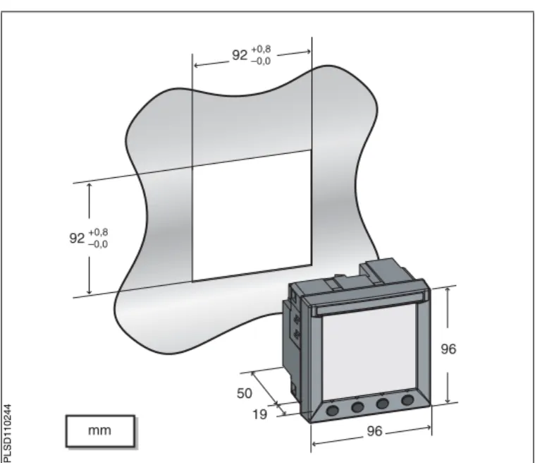
Dimensions
Figure 3 – 1: Power Meter dimensions
(3.62) 92+0.8–0.0
92+0.8 –0.0
(3.62)
mm (in.)
19 50 (1.97)
(0.75)
96 (3.78)
96 (3.78)
PLS
D
110
Chapter 3 — Installation 63230-510-200A1
Mounting 1/2006
ENG
LIS
H
Mounting
1. Insert the power meter through the 92 mm x 92 mm (3.62 in. x 3.62 in.) cut-out (see Figure 3 – 1 on page 7). 2. Attach the two retainer clips to
the power meter using the retainer slots at position A or position B.
There are two sets of retainer slots on the left, right, top and bottom of the power meter. The first set is for installation locations thinner than 3 mm (1/8 in.). The second set is for installation locations 3 to 6 mm (1/8 in. to 1/4 in.). NOTE: For use on a flat surface of a protective enclosure (for example, in the USA: NEMA Type 1 rated enclosure or better.
B
A
A
B
P
LSD1
1024
63230-510-200A1 Chapter 3 — Installation
1/2006 Removing the Connectors
ENG
LI
SH
Removing the Connectors
1. Insert the flat end of a screwdriver into the groove between the power meter and the connector, as shown in the image.
2. Pull down the screwdriver to remove the connector.
1
2
PLSD11025
Chapter 3 — Installation 63230-510-200A1
Removing the Connectors 1/2006
ENG
LIS
63230-510-200A1 Chapter 4 — Wiring
1/2006 Introduction
ENG
LI
SH
CHAPTER 4 — WIRING
Introduction
This chapter explains how to make the wiring connections for the power meter.
NOTE: Voltage inputs and control power for distribution systems up to 277 V L-N and 480 V L-L complies with metering category III. Also, terminal wiring should have a minimum temperature rating of 80°C.
The following symbols are used in the diagrams:
Table 4 – 1: Wiring Diagram Symbols
Symbol Description
Voltage disconnect switch
Fuse
Earth ground
Current transformer
Shorting block
Potential transformer
Protection containing a voltage disconnect switch with a fuse or disconnect circuit breaker (the protection device must be rated for the available short-circuit current at the connection point).
Chapter 4 — Wiring 63230-510-200A1
Supported System Types 1/2006
ENG
LIS
H
Supported System Types
Table 4 – 2: Voltages Less Than or Equal to 277 Vac L-N/480 Vac L-L, Direct Connect No PTs
Single-Phase Wiring
Number of Wires
CTs Voltage Connections Meter Configuration
Figure Number
Qty. ID Qty. ID Type System Type PT Primary Scale
2 1 I1 2 V1, Vn L-N 10 No PT 4 – 1
2 1 I1 2 V1, V2 L-L 11 No PT 4 – 2
3 2 I1, I2 3 V1, V2, Vn L-L with N 12 No PT 4 – 3 Three-Phase Wiring
3 2 I1, I3 3 V1, V2, V3 Delta 30 No PT 4 – 4
3 I1, I2, I3 3 V1, V2, V3 Delta 31 No PT 4 – 5
3 1 I1 3 V1, V2, V3 Delta
(Balanced)
32 No PT 4 – 15
4 3 I1, I2, I3 3 V1, V2, V3, Vn 4-wire Delta
40 No PT 4 – 6
4 3 I1, I2, I3 3 V1, V2, V3, Vn Wye 40 No PT 4 – 6
4 1 I1 3 V1, V2, V3, Vn Wye
(Balanced) 44 No PT 4 – 14
Table 4 – 3: Voltages Greater Than 277 Vac L-N/480 Vac L-L
Three-Phase Wiring Number of
Wires
CTs Voltage Connections Meter Configuration Figure
Number
Qty. ID Qty. ID Type System Type PT Primary Scale
3
2 I1, I3 2 V1, V3 (V2 to Ground) Delta 30 Based on voltage 4 – 7
3 I1, I2, I3 2 V1, V3 (V2 to Ground) Delta 31 Based on voltage 4 – 8
3 1 I1 2 V1, V3 (V2 to Ground (Balanced)Delta 32 Based on voltage 4 – 13
4
3 I1, I2, I3 3 V1, V2, V3, (Vn to Ground) Grounded Wye 40 Based on voltage 4 – 9
3 I1, I2, I3 2 V1, V3 (Vn to Ground) Wye 42 Based on voltage 4 – 10
2 I1, I2, I3 3 V1, V2, V3 (Vn to Ground) Grounded Wye 40 Based on voltage 4 – 11
4 1 I1 3 V1, V2, V3 (Vn
Grounded
63230-510-200A1 Chapter 4 — Wiring
1/2006 Wiring Diagrams
ENG
LI
SH
Wiring Diagrams
Figure 4 – 1: 1-Phase Line-to-Neutral
2-Wire System 1 CT Figure 4 – 2: 1-Phase Line-to-Line 2-Wire System 1 CT
t Use system type 10.1 t Use system type 11.1
Figure 4 – 3: 1-Phase Direct Voltage Connection 2 CT
Figure 4 – 4: 3-Phase 3-Wire 2 CT no PT
t Use system type 12.1
N L1 S2 S1 V1 V2 V3 VN I1+ I1– I2+ I2– I3+ I3– 3 4 5 6 14 15 16 17 18 19 PM200 L1 L2 S2 S1 V1 V2 V3 VN I1+ I1– I2+ I2– I3+ I3– 3 4 5 6 14 15 16 17 18 19 PM200
VL-L<= 480 V
L1 L2 S2 S1 S2 S1 N V1 V2 V3 VN I1+ I1– I2+ I2– I3+ I3– 3 4 5 6 14 15 16 17 18 19 PM200
Chapter 4 — Wiring 63230-510-200A1
Wiring Diagrams 1/2006
ENG
LIS
H
Figure 4 – 5: 3-Phase 3-Wire 3 CT no PT Figure 4 – 6: 3-Phase 4-Wire Wye Direct Voltage Input Connection 3 CT
t Use system type 31. • Use system type 40.2
Figure 4 – 7: 3-Phase 3-Wire Delta
Connection 2 CT 2 PT Figure 4 – 8: 3-Phase 3-Wire Delta Connection 3CT 2PT
t For an open delta PT connection with 120 V L-L
secondaries, use system type 30.
t Use System type 31.3
L2 L3 L1 S2 S1 S2 S1 S2 S1 V1 V2 V3 VN I1+ I1– I2+ I2– I3+ I3– 3 4 5 6 14 15 16 17 18 19 PM200
L2 L3 L1 N S2 S1 S2 S1 S2 S1 V1 V2 V3 VN I1+ I1– I2+ I2– I3+ I3– 3 4 5 6 14 15 16 17 18 19 PM200
L2 L3 L1 S2 S1 S2 S1 V1 V2 V3 VN I1+ I1– I2+ I2– I3+ I3– 3 4 5 6 14 15 16 17 18 19 PM200
63230-510-200A1 Chapter 4 — Wiring
1/2006 Wiring Diagrams
ENG
LI
SH
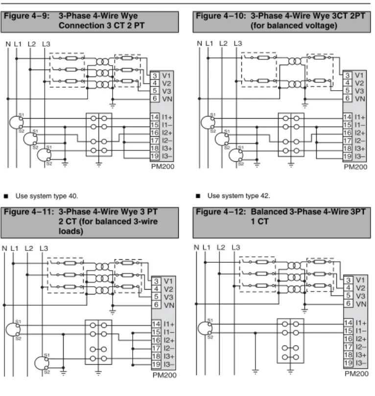
Figure 4 – 9: 3-Phase 4-Wire Wye Connection 3 CT 2 PT
Figure 4 – 10: 3-Phase 4-Wire Wye 3CT 2PT (for balanced voltage)
t Use system type 40. t Use system type 42.
Figure 4 – 11: 3-Phase 4-Wire Wye 3 PT 2 CT (for balanced 3-wire loads)
Figure 4 – 12: Balanced 3-Phase 4-Wire 3PT 1 CT
t Use system type 40. t Use system type 44
L2 L3
L1 N V1 V2 V3 VN I1+ I1– I2+ I2–
I3+
I3–
3 4 5 6 14 15 16 17 18 19 PM200 S2 S1 S2 S1 S2 S1
L2 L3
L1 N V1 V2 V3 VN I1+ I1– I2+ I2–
I3+
I3–
3 4 5 6 14 15 16 17 18 19 PM200 S2 S1 S2 S1 S2 S1
L2 L3
L1 N V1 V2 V3 VN I1+ I1– I2+ I2–
I3+
I3–
3 4 5 6 14 15 16 17 18 19 PM200 S2 S1 S2 S1
L2 L3
L1 N V1 V2 V3 VN I1+ I1– I2+ I2–
I3+
I3–
Chapter 4 — Wiring 63230-510-200A1
Wiring Diagrams 1/2006
ENG
LIS
H
Figure 4 – 13: Balanced 3-Phase 3-Wire 1 CT 2 PT
Figure 4 – 14: Balanced 3-Phase 4-Wire Direct Voltage Input Connection 1 CT
t Use system type 32 t Use system type 44
Figure 4 – 15: Balanced 3-Phase 3-Wire Direct Voltage Input Connection 1 CT
Use system type 32
L2 L3
L1 V1 V2 V3 VN I1+ I1– I2+ I2–
I3+
I3–
3 4 5 6 14 15 16 17 18 19 PM200 S2 S1
L2 L3
L1 N S2 S1 V1 V2 V3 VN I1+ I1– I2+ I2–
I3+
I3–
3 4 5 6 14 15 16 17 18 19 PM200
63230-510-200A1 Chapter 4 — Wiring
1/2006 Wiring Diagrams
ENG
LI
SH
1To avoid distortion, use parallel wires for control power and voltage inputs. Keep the fuse close to the power source. 2Use with 480Y/277 V and 208Y/120 V systems.
3For an open delta PT connection with 120 V L-L secondaries, use system type 31.
Figure 4 – 16: Direct Connect Control Power (Phase to Phase)
Figure 4 – 17: Direct Connect Control Power (Phase to Neutral)
t Phase to Phase only when voltage < 415 + 10% Vac
max.
t See Table 4 – 4 on page 18.
t Phase to Neutral only when voltage < 300 + 10%
Vac max.
t See Table 4 – 4 on page 18.
Figure 4 – 18: Direct Connect Control Power (DC Control Power)
Figure 4 – 19: Control Power Transformer (CPT) Connection
t DC Control Power 100 Vdc < V < 300 Vdc t See Table 4 – 4 on page 18.
t Control Power Transformer
120 or 240 Vac Secondary 50 VA max.
t See Table 4 – 4 on page 18.
L1 L2 L3
1 2
PM200
L1 L2 L3
1 2
PM200 N
PM200 1 2
L1 L2 L3 N
Chapter 4 — Wiring 63230-510-200A1
Wiring Diagrams 1/2006
ENG
LIS
H Table 4 – 4: Fuse Recommendation
Control Power Source Source Voltage (Vs) Fuse Fuse Amperage
CPT Vs ≤125 V FNM or MDL 250 mA
CPT 125 < Vs ≤ 240 V FNQ or FNQ-R 250 mA
CPT 240 < Vs ≤305 V FNQ or FNQ-R 250 mA
Line Voltage Vs ≤ 240 V FNQ-R 250 mA
Line Voltage Vs> 240 V FNQ-R 250 mA
DC Vs ≤ 300 V LP-CC 500 mA
NOTES:
t See Figure 4 – 16 to Figure 4 – 19 on page 17.
t Over current protection should be located as close to the device as possible.
t For selecting fuses and circuit breakers other than those listed above, use the following criteria: y Over current protection should be rated as listed above.
y Current interrupt capacity should be selected based on the installation category and fault current capability. y Over current protection should be selected with a time delay.
y The voltage rating should be based on the input voltage applied.
63230-510-200A1 Chapter 4 — Wiring 1/2006 Pulse Output Capabilities (PM200P)
ENG
LI
SH
Pulse Output Capabilities (PM200P)
Solid-state Pulse Output
There are two solid-state KY outputs. One is dedicated to kWH and the other is dedicated to kVARH. The maximum pulse rate is three (3) pulses per second with a pulse duration of 10 milliseconds.
Figure 4 – 20: Solid-state Outputs
*Pulse outputs are not SELV (safety extra low voltage) rated, so power sources should not be SELV circuits.
≤ 100 mA
~=
≤ 100 mA
~= 3
4 5 6
KWH KVARH
PM
200
P
Digital Output / Pulse Output KY is a solid state pulse output rated for 240 Vac/dc max.
Maximum load current is 100 mA at 25°C. Derate 0.56 mA per °C above 25°C.
NOTE: The overcurrent protective device must be rated for the short circuit current at the connection point.
Overcurrent Protective Device (not supplied)
Power Source * 3 - 240 Vdc 6 - 240 Vac
Load
Load
Chapter 4 — Wiring 63230-510-200A1 Pulse Output Capabilities (PM200P) 1/2006
ENG
LIS
63230-510-200A1 Chapter 5 — Communications (PM210) 1/2006 Communications Capabilities (PM210)
ENG
LI
SH
CHAPTER 5 — COMMUNICATIONS (PM210)
Communications Capabilities (PM210)
Daisy-chaining Devices to the Power Meter
The RS-485 slave port allows the power meter to be connected in a daisy chain with up to 31, 2-wire devices. In this bulletin, communications link refers to a chain of devices that are connected by a communications cable. See Figure 5 – 1.
t If the power meter is the first device on the daisy chain, connect it to the host device using a RS-232 to RS-422/RS-485 converter.
t If the power meter is the last device on the daisy chain, terminate it with the terminator provided. t See Table 5 – 1 for the maximum daisy-chain communications distances for 2-wire devices.
Table 5 – 1: RS-485 Communications Distances
Baud Rate
Maximum Communication Distances 1 to 32 Devices
Feet Meters
9600 8,000 2,438
19200 6,000 1,829
NOTE: Distances listed should be used as a guide only and cannot be guaranteed for non-POWERLOGIC devices. Refer to the master device’s documentation for any additional distance limitations.
Figure 5 – 1: Daisy-chaining 2-wire devices
– +
D L D L
0 1
Power Meter 210 or other POWERLOGIC 2-wire compatible devices Belden 9841 or equivalent
Belden 9841 wire colors: blue with white stripe (+), white with blue stripe (–), and silver (shield) MCT2W-485 terminator on the
last device of the daisy chain
PLS
D
110
087
Chapter 5 — Communications (PM210) 63230-510-200A1 Daisy-chaining Devices to the Power Meter 1/2006
ENG
LIS
63230-510-200A1 Chapter 6 — Operation
1/2006 Operating the Display
ENG
LI
SH
CHAPTER 6 — OPERATION
Operating the Display
The power meter is equipped with a large, back-lit LCD display. It can display up to five lines of information plus a sixth row of menu options. Figure 6 – 1 shows the different parts of the power meter.
Figure 6 – 1: Power Meter Display
A. Type of measurement B. Screen Title C. Maintenance icon D. Bar Chart (%) E. Units
F. Display more menu items G. Menu item
H. Selected menu indicator I. Button
J. Return to previous menu K. Values
L. Phase
0(!3% -!8$%-!.$
$-$ 0%!+
ZZZZZ\\\\\\!
!
!
.
)
! ZZZZZ\\\\\\
ZZZZZ\\\\\\
A B C
D
F
G H J
K L
I
E
P
LSD1
1023
Chapter 6 — Operation 63230-510-200A1
Menu Overview 1/2006
ENG
LIS
H
How the Buttons Work
NOTE:
t Each time you read “press” in this manual, press and release the appropriate button beneath a menu item. For example, if you are asked to “Press PHASE,” you would press and release the button below the PHASE menu item.
t Changes are automatically saved.
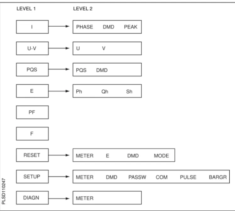
Menu Overview
Figure 6 – 2 on page 25 shows the menu items of the first two levels of the power meter. Level 1 contains all of the menu items available on the first screen of the power meter. Selecting a Level 1 menu item takes you to the next screen level containing the Level 2 menu items.
NOTE: The ###: is used to scroll through all menu items on a level.
Table 6 – 1: Button Symbols
Navigation
--->
View more menu items on the current level.1;
Return to the previous menu level.^
Indicates the menu item is selected and there are no menu levels below the current level.Change Values
+
Change values or scroll through the available options. When the end of a range is reached, pressing + again returns to the first value or option.<-
Select the next number of a series.63230-510-200A1 Chapter 6 — Operation
1/2006 Menu Overview
ENG
LI
SH
Figure 6 – 2: Abbreviated List of IEC Power Meter Menu Items
PHASE DMD PEAK
U V
Ph Qh Sh PQS DMD
METER DMD PASSW COM PULSE BARGR
METER U-V
PQS
E
PF
F
RESET
SETUP
DIAGN
METER E DMD MODE I
LEVEL 1 LEVEL 2
PL
SD11
Chapter 6 — Operation 63230-510-200A1
Menu Overview 1/2006
ENG
LIS
63230-510-200A1 Chapter 7 — Power Meter Setup
1/2006 Set Up the Power Meter
ENG
LI
SH
CHAPTER 7 — POWER METER SETUP
Set Up the Power Meter
To begin power meter setup, do the following: 1. Press ###: until you see SETUP. 2. Press SETUP.3. Enter your password.
NOTE: The default password is 00000.
Set Up CTs
1. Press ###: until METER is visible.
2. Press METER. 3. Press CT.
4. Enter the PRIM CT (primary CT) number: 1 to 32762. 5. Press OK.
6. Enter the SECON. CT (secondary CT) number: 1 or 5.
7. Press OK.
8. Press 1; to return to the
SETUP MODE screen.
<-CT RATIO
1; + OK
800
5
PRIM
SECON. C T
C T
PL
SD11
Chapter 7 — Power Meter Setup 63230-510-200A1
Set Up the Power Meter 1/2006
ENG
LIS
H
Set Up PTs
Set Up the System Frequency
1. Press ###: until METER is visible.
2. Press METER. 3. Press PT.
4. Select the SCALE value: x1, x10, x100, NO PT (for direct connect).
5. Press OK.
6. Enter the PRIM (primary) value.
7. Press OK.
8. Enter the SEC. (secondary) value.
9. Press OK.
10. Press 1; to return to the SETUP MODE screen.
1. Press ###: until METER is visible.
2. Press METER.
3. Press ###: until F (system frequency) is visible. 4. Press F.
5. Select the frequency: 50 Hz or 60 Hz.
6. Press OK.
7. Press 1; to return to the SETUP MODE screen.
<-PT RATIO
1; + OK
1200
120
PRIM SEC.
X
10
SCALEPLS
D
110
112
<-SYSTEM Frequency
1; + OK
60
60
Hz
FREQ.
&
P
LS
D
1102
63230-510-200A1 Chapter 7 — Power Meter Setup
1/2006 Set Up the Power Meter
ENG
LI
SH
Set Up the Meter System Type
Set Up Demand Current
1. Press ###: until METER is visible.
2. Press METER. 3. Press ###: until SYS
(system type) is visible. 4. Press SYS.
5. Select the SYS (system type): 10, 11, 12, 30, 31, 32, 40, 42, 44.
6. Press OK.
7. Press 1; to return to the SETUP MODE screen.
1. Press ###: until DMD (demand) is visible. 2. Press DMD. 3. Press I (current). 4. Enter the MIN (demand
interval in minutes): 1 to 60. 5. Press OK.
6. Press 1; to return to the SETUP MODE screen. NOTE: The calculation method used is Thermal.
<-3-PHASE SYSTEM
1; + OK
Chapter 7 — Power Meter Setup 63230-510-200A1
Set Up the Power Meter 1/2006
ENG
LIS
H
Set Up PQS Demand
1. Press ###: until DMD (demand) is visible. 2. Press DMD.
3. Press PQS (real, reactive, apparent power). 4. Enter the MIN (interval in
minutes): 1 to 60. 5. Enter the SUB-I (number of
subintervals): 0 to 60 6. Press OK.
7. Press 1; to return to the SETUP MODE screen. NOTE: The calculation method used for SUB-I is as follows: 0 = sliding block 1 = block
>1 = rolling block (The SUB-I value must divide evenly into the MIN value. For example, if MIN is 15, SUB-I can be 3, 5, or 15. If you selected 3, you would have 3 subintervals at 5 minutes each.)
013$%-!.$
/+
-).35"H
+6!2(
-3%#
)
P
LSD1
63230-510-200A1 Chapter 7 — Power Meter Setup
1/2006 Set Up the Power Meter
ENG
LI
SH
Set Up the Passwords
Set Up the Pulses (PM200P)
1. Press ###: until PASSW (password) is visible. 2. Press PASSW.
3. Enter the SETUP password. 4. Press OK.
5. Enter the RESET (password to reset the power meter) password.
6. Press OK to return to the SETUP MODE screen.
1. Press ###: until PULSE is visible.
2. Press PULSE.
3. Select the MSEC (kWH pulse duration in milliseconds): 10, 50, 100, 300, 500, or 1000. 4. Select the kWH/P (pulse
weight): 0.1, 1, 10, 100, 1000, 10000, or 100000. 5. Select the MSEC (kVARH
pulse duration in milliseconds): 10, 50, 100, 300, 500, or 1000. 6. Select the kVARH (pulse
weight): 0.1, 1, 10, 100, 1000, 10000, or 100000. 7. Press OK to return to the
SETUP MODE screen.
Chapter 7 — Power Meter Setup 63230-510-200A1
Set Up the Power Meter 1/2006
ENG
LIS
H
Set Up the Bargraph Scale
Set Up Communications (PM210)
1. Press ###: until BARGR (Bargraph) is visible. 2. Press BARGR.
3. Enter the %CT (percent of CT primary to represent 100 on the bargraph).
4. Press OK.
5. Press 1; to return to the SETUP MODE screen.
1. Press ###: until COM is visible.
2. Press COM. 3. Enter the ADDR (meter
address): 1 to 247. 4. Press OK.
5. Select the BAUD (baud rate): 2400, 4800, 9600 or 19200. 6. Press OK.
7. Select the parity: EVEN, ODD, NONE.
8. Press OK to return to the SETUP MODE screen.
"!2'2!0(3#!,%
/+
#4!
LATR !$$2
P
LS
D
1102
43
#/-3%450
/+
M/M%
A@T$0@Q
LATR !$$2
P
LSD1
1024
63230-510-200A1 Chapter 7 — Power Meter Setup
1/2006 Power Meter Diagnostics
ENG
LI
SH
Select the Operating Mode
Power Meter Diagnostics
View the Meter Information
1. Press ###: until RESET is visible.
2. Press RESET.
3. Enter the RESET password (00000 is the default). 4. Press OK.
5. Press ###: until MODE is visible.
6. Press MODE. 7. Press IEEE or IEC. 8. Press 1; to return to the
RESET MODE screen. 9. Press 1; to return to the
previous screen.
1. Press ###: until DIAGN (diagnostics) is visible. 2. Press DIAGN.
3. Press METER (meter info). 4. View the meter information (model number, firmware operating system version, firmware reset system version, and power meter serial number). 5. Press 1; to return to the
previous screen.
SELECT MODE
1; IEEE IEC
P
LS
D
1102
52
-%4%2 -%4%2).&/
23
3.
-/$%,
>
PLS
D
110
Chapter 7 — Power Meter Setup 63230-510-200A1
Reset the Power Meter 1/2006
ENG
LIS
H
Reset the Power Meter
Restore Power Meter Default Settings
1. Press ###: until RESET is visible.
2. Press RESET.
3. Enter the RESET password (00000 is the default). 4. Press OK.
5. Press ###: until METER is visible.
6. Press METER. 7. Press NO or YES. 8. Press 1; to return to the
previous screen.
INIT METER?
No Yes
PL
SD11
63230-510-200A1 Chapter 8 — Maintenance and Troubleshooting
1/2006 Introduction
ENG
LI
SH
CHAPTER 8 — MAINTENANCE AND TROUBLESHOOTING
Introduction
The power meter does not contain any user-serviceable parts. If the power meter requires service, contact your local sales representative. Do not open the power meter. Opening the power meter voids the warranty.
Getting Technical Support
Please refer to the Technical Support Contacts provided in the power meter shipping cartonfor a list of support phone numbers by country.
Troubleshooting
The information in Table 8 – 1 describes potential problems and their possible causes. It also describes checks you can perform or possible solutions for each. After referring to this table, if you cannot resolve the problem, contact the your local Square D/Schneider Electric sales representative for assistance.
DANGER
HAZARD OF ELECTRIC SHOCK, EXPLOSION, OR ARC FLASH
t This equipment must be installed and serviced only by qualified electrical personnel. t Turn off all power supplying this equipment before working on or inside.
t Always use a properly rated voltage sensing device to confirm that all power is off. t Apply appropriate personal protective equipment (PPE) and follow safe electrical work
practices. See NFPA 70E.
t Carefully inspect the work area for tools and objects that may have been left inside the equipment.
t Use caution while removing or installing panels so that they do not extend into the energized bus; avoid handling the panels, which could cause personal injury.
Chapter 8 — Maintenance and Troubleshooting 63230-510-200A1
Troubleshooting 1/2006
ENG
LIS
H Table 8 – 1: Troubleshooting
Potential Problem Possible Cause Possible Solution
The maintenance icon is illuminated on the power meter display.
tThe metered voltage is over the voltage range. tThe metered current is over the current range. tThe metered frequency is out of the frequency
range.
NOTE: Refer to “Measurement Accuracy” in Table A – 1 on page 39 for a list of measurement ranges.
Correct the out of range condition.
The display is blank after applying control power to the power meter.
The power meter may not be receiving the necessary power.
tVerify that the power meter line (L) and
neutral (N) terminals (terminals 25 and 27) are receiving the necessary power.
tVerify that the heartbeat LED is blinking. tCheck the fuse.
The data being displayed is inaccurate or not what you expect.
Incorrect setup values. Check that the correct values have been entered for power meter setup parameters (CT and PT ratings, System Type, Nominal Frequency, and so on). See “Set Up the Power Meter” on page 27 for setup instructions.
Incorrect voltage inputs. Check power meter voltage input terminals to verify that adequate voltage is present. Power meter is wired improperly. Check that all CTs and PTs are connected
63230-510-200A1 Chapter 8 — Maintenance and Troubleshooting
1/2006 Troubleshooting
ENG
LI
SH
Cannot communicate with power meter from a remote personal computer.
Power meter address is incorrect. Check to see that the power meter is correctly addressed. See “Set Up Communications (PM210)” on page 32 for instructions. Power meter baud rate is incorrect. Verify that the baud rate of the power meter
matches the baud rate of all other devices on its communications link. See “Set Up Communications (PM210)” on page 32 for instructions.
Communications lines are improperly
connected. Verify the power meter communications connections. Refer to the Communications chapter for instructions.
Communications lines are improperly
terminated. Check to see that a multipoint communications terminator is properly installed. See Figure 5 – 1 on page 21for instructions.
Incorrect route statement to power meter. Check the route statement. Refer to the SMS online help for instructions on defining route statements.
Chapter 8 — Maintenance and Troubleshooting 63230-510-200A1
Troubleshooting 1/2006
ENG
LIS
63230-510-200A1 Appendix A — Specifications
1/2006 Power Meter Specifications
ENG
LI
SH
APPENDIX A — SPECIFICATIONS
Power Meter Specifications
Table A – 1: Specifications
Electrical Characteristics
Type of measurement True rms up to the 15th harmonic on single- or three-phase AC system (3P, 3P + N)
32 samples per cycle Measurement Accuracy Voltage 90 to 277 V L-N ±0.4% of nominal
Current 0.5 to 1 A ±0.8% of reading 1 to 6 A ±0.5% of reading
Power ±1%
Frequency 45 to 65 ±0.04 Hz Real Energy IEC 62053-21 Class 1 Reactive Energy IEC 62053-23 Class 2
Data update rate 1 s
Input-voltage Measured voltage 10 to 480 V AC (direct L-L, nominal) 10 to 277 V AC (direct L-N, nominal) 10 to 1.6 MV AC (with external VT) Metering over-range 1.2 Un
Impedance 2 MΩ (L-L) / 1 MΩ (L-N) Frequency range 45 to 65 Hz
Input-current CT ratings Primary Adjustable from 5 A to 32767 A Secondary 1 A or 5 A
Measurement input range 10 mA to 6 A Permissible overload 10 A continuous
50 A for 10 seconds per hour 120 A for 1 second per hour Impedance < 0.1 Ω
Load < 0.15 VA
Control Power AC 100 to 415 ±10% V AC, 5 VA; 50 to 60 Hz
DC 125 to 250 ±20% V DC, 3W
Appendix A — Specifications 63230-510-200A1
Power Meter Specifications 1/2006
ENG
LIS
H
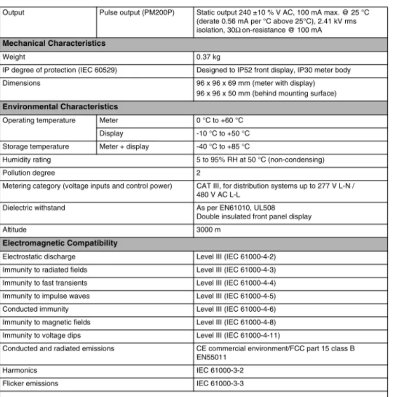
Output Pulse output (PM200P) Static output 240 ±10 % V AC, 100 mA max. @ 25 °C (derate 0.56 mA per °C above 25°C), 2.41 kV rms isolation, 30Ω on-resistance @ 100 mA
Mechanical Characteristics
Weight 0.37 kg
IP degree of protection (IEC 60529) Designed to IP52 front display, IP30 meter body
Dimensions 96 x 96 x 69 mm (meter with display)
96 x 96 x 50 mm (behind mounting surface)
Environmental Characteristics
Operating temperature Meter 0 °C to +60 °C
Display -10 °C to +50 °C
Storage temperature Meter + display -40 °C to +85 °C
Humidity rating 5 to 95% RH at 50 °C (non-condensing)
Pollution degree 2
Metering category (voltage inputs and control power) CAT III, for distribution systems up to 277 V L-N / 480 V AC L-L
Dielectric withstand As per EN61010, UL508
Double insulated front panel display
Altitude 3000 m
Electromagnetic Compatibility
Electrostatic discharge Level III (IEC 61000-4-2) Immunity to radiated fields Level III (IEC 61000-4-3) Immunity to fast transients Level III (IEC 61000-4-4) Immunity to impulse waves Level III (IEC 61000-4-5)
Conducted immunity Level III (IEC 61000-4-6)
Immunity to magnetic fields Level III (IEC 61000-4-8) Immunity to voltage dips Level III (IEC 61000-4-11)
Conducted and radiated emissions CE commercial environment/FCC part 15 class B EN55011
Harmonics IEC 61000-3-2
Flicker emissions IEC 61000-3-3
63230-510-200A1 Appendix A — Specifications
1/2006 Power Meter Specifications
ENG
LI
SH
Safety
Europe CE, as per IEC 61010-1
U.S. and Canada UL508
Communications
RS485 port (PM210) 2-wire, up to 19200 baud, Modbus RTU
Display Characteristics
Dimensions 73 x 69 mm Back-lit green LCD (6 lines total, 4 concurrent values)
Appendix A — Specifications 63230-510-200A1
Power Meter Specifications 1/2006
ENG
LIS
63230-510-200A1 Appendix B — Glossary
1/2006 Glossary
ENG
LI
SH
APPENDIX B — GLOSSARY
Glossary
accumulated energy—energy can accumulates in either signed or unsigned (absolute) mode. In signed mode, the direction of power flow is considered and the accumulated energy magnitude may increase and decrease. In absolute mode, energy accumulates as a positive regardless of the power flow direction.
baud rate—specifies how fast data is transmitted across a network port.
block interval demand— power demand calculation method for a block of time and includes three ways to apply calculating to that block of time using the sliding block, fixed block, or rolling block method.
communications link—a chain of devices connected by a communications cable to a communications port.
current transformer (CT)—current transformer for current inputs.
demand—average value of a quantity, such as power, over a specified interval of time.
device address—defines where the power meter resides in the power monitoring system.
event—the occurrence of an alarm condition, such as Undervoltage Phase A, configured in the power meter.
firmware—operating system within the power meter
fixed block—an interval selected from 1 to 60 minutes (in 1-minute increments). The power meter calculates and updates the demand at the end of each interval.
float—a 32-bit floating point value returned by a register (see Appendix C —Register List on page 47). The upper 16-bits are in the lowest-numbered register pair. For example, in the register 4010/11, 4010 contains the upper 16-bits while 4011 contains the lower 16-16-bits.
frequency—number of cycles in one second.
line-to-line voltages—measurement of the rms line-to-line voltages of the circuit.
line-to-neutral voltages—measurement of the rms line-to-neutral voltages of the circuit.
maximum demand current—highest demand current measured in amperes since the last reset of demand.
maximum demand real power—highest demand real power measured since the last rest of demand.
maximum demand—the highest average load during a specified time interval. See also peak demand.
maximum value—highest value recorded of the instantaneous quantity such as Phase A Current, Phase A Voltage, etc., since the last reset of the minimums and maximums.
nominal—typical or average.
parity—refers to binary numbers sent over the communications link. An extra bit is added so that the number of ones in the binary number is either even or odd, depending on your configuration). Used to detect errors in the transmission of data.
Appendix B — Glossary 63230-510-200A1
Glossary 1/2006
ENG
LIS
H
peak demand—the highest average load during a specified time interval. See also maximum demand.
phase currents (rms)—measurement in amperes of the rms current for each of the three phases of the circuit. See also maximum value.
phase rotation—phase rotations refers to the order in which the instantaneous values of the voltages or currents of the system reach their maximum positive values. Two phase rotations are possible: A-B-C or A-C-B.
potential transformer (PT)—also known as a voltage transformer
power factor (PF)—true power factor is the ratio of real power to apparent power using the complete harmonic content of real and apparent power. Calculated by dividing watts by volt amperes. Power factor is the difference between the total power your utility delivers and the portion of total power that does useful work. Power factor is the degree to which voltage and current to a load are out of phase.
real power—calculation of the real power (3-phase total and per-phase real power calculated) to obtain kilowatts.
rms—root mean square. Power meters are true rms sensing devices.
rolling block—a selected interval and subinterval that the power meter uses for demand calculation. The subinterval must divide evenly into the interval. Demand is updated at each subinterval, and the power meter displays the demand value for the last completed interval.
scale factor—multipliers that the power meter uses to make values fit into the register where information is stored.
safety extra low voltage (SELV) circuit—a SELV circuit is expected to always be below a hazardous voltage level.
short integer—a signed 16-bit integer (see Appendix C —Register List on page 47).
sliding block—an interval selected from 1 to 60 minutes (in 1-minute increments). If the interval is between 1 and 15 minutes, the demand calculation updates every 15 seconds. If the interval is between 16 and 60 minutes, the demand calculation updates every 60 seconds. The power meter displays the demand value for the last completed interval.
SMS—see System Manager Software.
System Manager Software (SMS)—software designed by POWERLOGIC for use in evaluating power monitoring and control data.
system type—a unique code assigned to each type of system wiring configuration of the power meter.
thermal demand—demand calculation based on thermal response.
total power factor—see power factor.
true power factor—see power factor.
unsigned integer—an unsigned 16-bit integer (see Appendix C —Register List on page 47).
unsigned long integer—an unsigned 32-bit value returned by a register (see Appendix C — Register List on page 47). The upper 16-bits are in the lowest-numbered register pair. For example, in the register pair 4010 and 4011, 4010 contains the upper 16-bits while 4011 contains the lower 16-bits.
63230-510-200A1 Appendix B — Glossary
1/2006 Abbreviations and Symbols
ENG
LI
SH
Abbreviations and Symbols
A—Ampere
ADDR—Power meter address
BARGR—Bargraph
COM—Communications
CPT—Control Power Transformer
CT—see current transformer on page 43
DMD—Demand
F—Frequency
I—Current
IMAX—Current maximum demand
kVA—Kilovolt-Ampere
kVAD—Kilovolt-Ampere demand
kVAR—Kilovolt-Ampere reactive
kVARD—Kilovolt-Ampere reactive demand
kVARH—Kilovolt-Ampere reactive hour
kW—Kilowatt
kWD—Kilowatt demand
kWH/P—Kilowatt-hours per pulse
KWMAX—Kilowatt maximum demand
MAINT—Maintenance screen
MBUS—MODBUS
MINS—Minutes
MSEC—Milliseconds
MVARh—Megavolt ampere reactive hour
MWh—Megawatt hour
O.S.—Operating System (firmware version)
P—Real power
PAR—Parity
PASSW—Password
Pd—Real power demand
PF—Power factor
Ph—Real energy
PM—Power meter
PQS—Real, reactive, apparent power
PQSd—Real, reactive, apparent power demand
PRIM—Primary
PT—Number of voltage connections (see potential transformer on page 44)
PULSE—Pulse
Q—Reactive power
Qd—Reactive power demand
Qh—Reactive energy
R.S.—Firmware reset system version
S—Apparent power
S.N.—Power meter serial number
SCALE—see scale factor on page 44
Sd—Apparent power demand
Appendix B — Glossary 63230-510-200A1
Abbreviations and Symbols 1/2006
ENG
LIS
H
SEC—Secondary
Sh—Apparent Energy
SUB-I—Subinterval
SYS—System Manager™ software (SMS) system type (ID)
U—Voltage line to line
63230-510-200A1 Appendix C — Register List
1/2006 Register List
ENG
LI
SH
APPENDIX C — REGISTER LIST
Register List
Register Units Scale Factor Range Description
4000 to
4001 kWh See register 4108 0 to 0xFFFFFFFF Real Energy Consumption 4002 to
4003 kVAh See register 4108 0 to 0xFFFFFFFF Apparent Energy Consumption 4004 to
4005 kVARh See register 4108 0 to 0xFFFFFFFF Reactive Energy Consumption 4006 kW See register 4107 0 to 32767 Total Real Power 4007 kVA See register 4107 0 to 32767 Total Apparent Power 4008 kVAR See register 4107 0 to 32767 Total Reactive Power
4009 — 0.0001 0 to 10000 Total Power Factor
4013 Hz 0.01 4500 to 6500 Frequency (derived from Phase A) 4014 kW See register 4107 0 to 32767 Total Real Power Present Demand 4015 kVA See register 4107 0 to 32767 Total Apparent Power Present Demand 4016 kVAR See register 4107 0 to 32767 Total Reactive Power Present Demand 4017 kW See register 4107 0 to 32767 Total Real Power Max Demand 4018 kVA See register 4107 0 to 32767 Total Apparent Power Max Demand 4019 kVAR See register 4107 0 to 32767 Total Reactive Power Max Demand 4020 Amp See register 4105 0 to 32767 Current, Instantaneous, Phase A 4021 Amp See register 4105 0 to 32767 Current, Instantaneous, Phase B 4022 Amp See register 4105 0 to 32767 Current, Instantaneous, Phase C 4024 Amp See register 4105 0 to 32767 Current, Present Demand, Phase A 4025 Amp See register 4105 0 to 32767 Current, Present Demand, Phase B 4026 Amp See register 4105 0 to 32767 Current, Present Demand, Phase C 4027 Amp See register 4105 0 to 32767 Current, Max Demand, Phase A 4028 Amp See register 4105 0 to 32767 Current, Max Demand, Phase B 4029 Amp See register 4105 0 to 32767 Current, Max Demand, Phase C 4030 Volt See register 4106 0 to 32767 Voltage, Phase A-B 4031 Volt See register 4106 0 to 32767 Voltage, Phase B-C
Appendix C — Register List 63230-510-200A1
Register List 1/2006
ENG
LIS
H 4032 Volt See register 4106 0 to 32767 Voltage, Phase A-C
4033 Volt See register 4106 0 to 32767 Voltage, Phase A-N 4034 Volt See register 4106 0 to 32767 Voltage, Phase B-N 4035 Volt See register 4106 0 to 32767 Voltage, Phase C-N
4105 — –4 = 0.0001
–3 = 0.001 –2 = 0.01 –1 = 0.1 0 = 1.0 1 = 10.0 2 = 100.0 3 = 1000.0 4 = 10000.0
Scale Factor I (current)
4106 — –4 = 0.0001
–3 = 0.001 –2 = 0.01 –1 = 0.1 0 = 1.0 1 = 10.0 2 = 100.0 3 = 1000.0 4 = 10000.0
Scale Factor V (voltage)
4107 — –4 = 0.0001
–3 = 0.001 –2 = 0.01 –1 = 0.1 0 = 1.0 1 = 10.0 2 = 100.0 3 = 1000.0 4 = 10000.0
Scale Factor W (power)
Register Units Scale Factor Range Description
t Registers 4000 – 4005, 7002, and 7003 are unsigned long integer values t Registers 4006 – 4104, 4109 – 7001, and 7004 – 7162 are unsigned integer values t Registers 4105 – 4108 are signed integer values
63230-510-200A1 Appendix C — Register List
1/2006 Register List
ENG
LI
SH
4108 — –4 = 0.0001
–3 = 0.001 –2 = 0.01 –1 = 0.1 0 = 1.0 1 = 10.0 2 = 100.0 3 = 1000.0 4 = 10000.0
Scale Factor E (energy)
4109 — — — Feature Bitmap (future use, always returns zero
presently)
4112 — — — Error Bitmap:
bit 0: Phase A Voltage over range bit 1: Phase B Voltage over range bit 2: Phase C Voltage over range bit 3: Phase A Current over range bit 4: Phase B Current over range bit 5: Phase C Current over range bit 6: Frequency out of range bit 7-15: Reserved for future use
4113 — — — Reserved, always returns 0
4114 — — — Reserved, always returns 0
4115 — — — Reserved, always returns 0
4116 — — — Reserved, always returns 0
4117 Minutes — 1 to 60 Thermal Demand Interval
4118 Minutes — 1 to 60 Power Block Demand Interval
4119 — — 0 to 60 Power Block Demand Sub-Intervals
If set to 0, a subinterval of 15 seconds is used for Demand Intervals less than or equal to 15 minutes, or 60 seconds for intervals greater than 15 minutes.
4120 — — 1 to 32767 CT Ratio – Primary
4121 — — 1 or 5 CT Ratio - Secondary
Register Units Scale Factor Range Description
t Registers 4000 – 4005, 7002, and 7003 are unsigned long integer values t Registers 4006 – 4104, 4109 – 7001, and 7004 – 7162 are unsigned integer values t Registers 4105 – 4108 are signed integer values
Appendix C — Register List 63230-510-200A1
Register List 1/2006
ENG
LIS
H 4122 — — 1 to 32767 PT Ratio - Primary
4123 — — 0,1,10,100 PT Ratio - Scale (0 = No PT)
4124 — — 100,110,115,120 PT Ratio – Secondary
4125 Hz — 50 or 60 Service Frequency
4126 — — N/A Reset
t Write 30078 to clear all Energy
Accumulators.
t Write 21212 to reset Peak Demand values
to Present Demand Values.
t Read always returns 0.
4127 — — 10,11,12,30, 31, 32,
40, 42, 44 System Type
4128 — — 0,1 Units: 0 = IEC, 1 = IEEE units
7000 — — 0 to 32767 Firmware Version, Reset System
7001 — — — Firmware Version, Operating System
7002/03 — — — Serial Number (date/time of mfg. in UTC)
7004 — — 15201 Device ID = 15201
7005 — — 1 to 247 Modbus Address
7006 — — 2400,4800,
9600,19200 Baud rate
Register Units Scale Factor Range Description
t Registers 4000 – 4005, 7002, and 7003 are unsigned long integer values t Registers 4006 – 4104, 4109 – 7001, and 7004 – 7162 are unsigned integer values t Registers 4105 – 4108 are signed integer values
63230-510-200A1 Appendix C — Register List
1/2006 Supported MODBUS Commands
ENG
LI
SH
Supported MODBUS Commands
Command Description
0x03 Read holding registers
0x04 Read input registers
0x06 Preset single registers
0x10 Preset multiple registers
0x11 Report ID
Return String byte 1: 0x11
byte 2: number of bytes following without crc byte 3: ID byte = 250
byte 4: status = 0xFF
bytes 5+: ID string = PM210 Power Meter last 2 bytes: CRC
0x2B Read device identification, BASIC implementation (0x00, 0x01, 0x02 data), conformity level 1,
Object Values
0x01: If register 4128 is 0, then “Merlin Gerin. If register 4128 is 1, then “Square D” 0x02: “PM210”
Appendix C — Register List 63230-510-200A1
Supported MODBUS Commands 1/2006
ENG
LIS
63230-510-200A1 Index 1/2006
ENG
LI
SH
CHAPTER 1 — INDEX
A
address
device addressEN–37
B
bargraph scale setupEN–32 baud rateEN–37 button
symbolsEN–24 buttons
how to useEN–24
C
communications capabilitiesEN–21 characteristicsEN–3 daisy-chaining devicesEN– 21 distancesEN–21 functionsEN–3 settingsEN–3 setupEN–32 troubleshootingEN–37 connections wiringEN–11 contacting technical support EN–35 CT setupEN–27 D demand setupEN–29 valuesEN–2 dimensions
power meterEN–7 display operationEN–23 E energy valuesEN–2 F
fuse recommendationsEN–18
G 35 I IECEN–33 IEEEEN–33 instantaneous rms valuesEN–2 M maintenance
of power meterEN–35 maximum demand
valuesEN–2 menu
list of menu itemsEN–25 overviewEN–24 menu modesEN–2 meter informationEN–33 MODBUSEN–3 mounting dimensionsEN–7 O operating mode IECEN–33 IEEEEN–33 operation displayEN–23 P password setupEN–31 power meter
box contentsEN–1 characteristicsEN–2 dimensionsEN–7 setupEN–27 PQS demand setupEN–30 problems
see troubleshootingEN–35 PT
setupEN–28 pulse outputEN–3 pulse setupEN–31
R
characteristicsEN–2 passwordEN–31 route statementEN–37 RS485EN–3
communications distancesEN–21
S
safety precautionsEN–5 setupEN–27
bargraph scaleEN–32 communicationsEN–32 CTEN–27
demandEN–29 passwordEN–31 PQS demandEN–30 PTEN–28 pulseEN–31 system frequencyEN–28 system typeEN–28, EN–29 symbols
above buttonsEN–24 wiringEN–11 system frequency
setupEN–28 system type
setupEN–28, EN–29 system typesEN–12
T
technical supportEN–35 thermal demand
valuesEN–2 troubleshootingEN–36
V
viewing meter informationEN– 33
W
wiring
fuse recommendationsEN– 18
Index 63230-510-200A1 1/2006
ENG
LIS
ESPAÑ
O
L
CHAPTER 1 — CATEGORÍAS DE RIESGOS Y SÍMBOLOS ESPECIALES
CATEGORÍAS DE RIESGOS Y SÍMBOLOS ESPECIALES
Lea estas instrucciones atentamente y examine el equipo para familiarizarse con el dispositivo antes de instalarlo, manipularlo, revisarlo o realizar el mantenimiento. Los siguientes mensajes especiales pueden aparecer a lo largo de este manual o en el equipo para advertir de posibles riesgos o remitirle a otras informaciones que le ayudarán a aclarar o simplificar los procedimientos.
NOTA: Proporciona información adicional para aclarar o simplificar procedimientos.
POR FAVOR, TENGA EN CUENTA LO SIGUIENTE
Sólo el personal de mantenimiento eléctrico cualificado puede instalar, manipular, revisar y realizar el mantenimiento del equipo eléctrico. Schneider Electric no asume ninguna responsabilidad por las posibles consecuencias derivadas de la utilización de este manual.
DECLARACIÓN DE CLASE B SEGÚN NORMATIVA FCC
Este equipo ha sido probado y cumple con los límites establecidos para los dispositivos digitales Clase B, según la sección 15 de la normativa FCC. Estos límites se establecen para proporcionar la protección adecuada contra interferencias que puedan dañar el equipo cuando éste se utiliza en un entorno comercial. Este equipo genera, utiliza y puede emitir energía de radiofrecuencia y, si no se instala y utiliza siguiendo las indicaciones del manual de instrucciones, puede provocar interferencias que afecten a las radiocomunicaciones. Si se utiliza en una zona residencial, las interferencias podrían causar interferencias dañinas. En tal caso, el usuario es el responsable de corregir dichas interferencias por su propia cuenta y riesgo. Este aparato digital Clase B cumple con
La adición de uno de estos dos símbolos a una etiqueta de seguridad de “Peligro” o “Advertencia” indica que existe un peligro eléctrico que podría causar lesiones personales si no se siguen las instrucciones.
Éste es el símbolo de alerta de seguridad. Sirve para alertar de posibles riesgos de daños personales. Siga las recomendaciones de todos los mensajes de seguridad precedidos por este símbolo para evitar posibles daños personales e incluso la muerte.
PELIGRO PELIGRO indica una situación de peligro inminente que, si no se evita, puede provocar la muerte o lesiones graves.
ADVERTENCIA
ADVERTENCIA indica una posible situación de peligro que, si no se evita, puede provocar la muerte o lesiones graves.
PRECAUCIÓN
PRECAUCIÓN indica una posible situación de peligro que, si no se evita, puede provocar lesiones leves o menos graves.
PRECAUCIÓN
ES
PAÑO
63230-510-200A1 Índice 1/2006
ESPAÑ
O
L
CAPÍTULO 1 — ÍNDICE
CATEGORÍAS DE RIESGOS Y SÍMBOLOS ESPECIALES . . . ES–I
INTRODUCCIÓN . . . ES–1
Contenido de la caja . . . ES–1 Identificación . . . ES–1 Características de la central de medida (PM200, PM200P y PM210) . . . ES–2 MODBUS RS485 (PM210) . . . ES–3 Salida de impulsos (PM200P) . . . ES–3
PRECAUCIONES DE SEGURIDAD . . . ES–5
Antes de empezar . . . ES–5
INSTALACIÓN . . . ES–7
Dimensiones . . . ES–7 Montaje . . . ES–8 Desmontaje de los conectores . . . ES–9
CABLEADO . . . ES–11
Introducción . . . ES–11 Tipos de sistemas compatibles . . . ES–12 Diagramas de cableado . . . ES–14 Recursos de salida de impulsos (PM200P) . . . ES–20 Salida de impulsos de estado sólido . . . ES–20
COMUNICACIONES (PM210) . . . ES–21
Recursos de comunicaciones (PM210) . . . ES–21 Conexión de dispositivos mediante bus de comunicaciones serie . . . ES–21
FUNCIONAMIENTO . . . ES–23
Funcionamiento de la pantalla . . . ES–23 Funcionamiento de los botones . . . ES–24 Descripción general de los menús . . . ES–24
CONFIGURACIÓN DE LA CENTRAL DE MEDIDA . . . ES–27
Índice 63230-510-200A1 1/2006
ES
PAÑO
L
Configuración de la escala de gráfico de barras . . . ES–32 Configuración de las comunicaciones (PM210) . . . ES–32 Selección del modo de funcionamiento . . . ES–33 Diagnósticos de la central de medida . . . ES–33 Visualización de la información de la central de medida . . . ES–33 Comprobación del estado del dispositivo . . . ES–34 Restablecimiento de la central de medida . . . ES–34 Restauración de la configuración predeterminada de la central de medida . . . ES–34
MANTENIMIENTO Y RESOLUCIÓN DE PROBLEMAS . . . ES–35
Introducción . . . ES–35 Asistencia técnica . . . ES–35 Resolución de problemas . . . ES–35
ESPECIFICACIONES . . . ES–39
Especificaciones de la central de medida . . . ES–39
GLOSARIO . . . ES–43
Glosario . . . ES–43 Abreviaturas y símbolos . . . ES–45
LISTA DE REGISTROS . . . ES–47
Lista de registros . . . . ES–47 Comandos MODBUS admitidos . . . ES–52