Por
Ant´
onio Jorge Felizardo Pereira
Orientador: Doutor Jo˜
ao Lu´ıs Hon´
orio Matias
Co-orientador: Doutor Pedro Miguel Mestre Alves da Silva
Disserta¸c˜ao submetida `a
UNIVERSIDADE DE TR ´AS-OS-MONTES E ALTO DOURO para obten¸c˜ao do grau de
MESTRE
em Engenharia Electrot´ecnica e de Computadores, de acordo com o disposto no Regulamento Geral dos Ciclos de Estudo Conducentes ao Grau de Mestre na UTAD
Doutor Jo˜ao Lu´ıs Hon´orio Matias
Professor Auxiliar do Departamento de Matem´atica, Da Escola de Ciˆencias e Tecnologia Universidade de Tr´as-os-Montes e Alto Douro
Doutor Pedro Miguel Mestre Alves da Silva
Professor Auxiliar do Departamento de Engenharias, Da Escola de Ciˆencias e Tecnologia Universidade de Tr´as-os-Montes e Alto Douro
to, my Parents
Ant´onio Jorge Felizardo Pereira
Submetido na Universidade de Tr´as-os-Montes e Alto Douro para o preenchimento dos requisitos parciais para obten¸c˜ao do grau de
Mestre em Engenharia Electrot´ecnica e de Computadores
Resumo — O matUTAD ´e uma plataforma para um jogo de matem´atica online, direcionado a estudantes desde o s´etimo at´e ao d´ecimo segundo ano de escolari-dade. Considerando que na sua implementa¸c˜ao (em 2003) foram usadas tecnologias que nos dias de hoje j´a se encontram em desuso para novas implementa¸c˜oes, assim como a metodologia ad-hoc que o seu desenvolvimento seguiu ao longo dos anos, surgiu a necessidade de redesenhar a plataforma a n´ıvel estrutural e tecnol´ogico, fornecendo assim uma aplica¸c˜ao bem documentada, desenvolvida com tecnologias recentes. O conceito de aplica¸c˜oes web responsivas tamb´em dever´a fazer parte desta reestrutura¸c˜ao de modo a permitir uma futura implementa¸c˜ao de uma plataforma m´ovel.
Tendo os problemas referidos anteriormente em considera¸c˜ao, esta disserta¸c˜ao tem como objetivo o desenvolvimento do Front-End para o matUTAD, come¸cando por uma pesquisa das tecnologias que poder˜ao ser usadas, passando de seguida para a sua implementa¸c˜ao num prot´otipo funcional, baseado nos requerimentos e diagramas estruturais estabelecidos em conjunto com o projeto de desenvolvimento do respetivo Back-End.
Palavras Chave: Web Applications, Front-End, JavaScript, HTML, CSS, MVC,
Flux, JavaScript Frameworks.
Ant´onio Jorge Felizardo Pereira
Submitted to the University of Tr´as-os-Montes and Alto Douro in partial fulfillment of the requirements for the degree of Master of Science in Electrical Engineering and Computers
Abstract — matUTAD is an online mathematics game platform for students from
seventh through twelfth grades. Considering the technologies used for its implemen-tation (in 2003), that are no longer used for new projects, as well as the ad-hoc methodology used for its development through the years, there was the need for a structural and technological redesign, providing a well documented application with a robust foundation and state of the art technologies. The concept of mobile web applications and responsive web design should also be taken into account, extending the application for a future mobile implementation.
Taking the concerns explained above into consideration, this thesis aims to develop the Front-End for matUTAD by conducting a research on the technologies that can be used for the development, translating into an implementation of a functional prototype of the application, based on the requirements and structural diagrams established in conjunction with the Back-End development project.
Key Words: Web Applications, Front-End, JavaScript, HTML, CSS, MVC, Flux,
JavaScript Frameworks.
I would first like to thank my thesis advisors, Professor Jo˜ao Lu´ıs Hon´orio Matias from the Mathematics Department of the Science and Technology School at Univer-sidade de Tr´as-os-Montes e Alto Douro, and Professor Pedro Miguel Mestre Alves da Silva from the Engineering Department of the Science and Technology School at Universidade de Tr´as-os-Montes e Alto Douro. Their guidance and availability dur-ing the development of this thesis were a determindur-ing factor for its success, allowdur-ing me to collect as much knowledge as possible for the project’s implementation, but also for my future, steering me in the right direction whenever necessary.
I would also like to thank my parents, Elisabete Felizardo and Jorge Penelas, not only for the continuous support through the thesis and academic life, but also for the opportunity to have the best possible education they could provide.
I would like to thank my girlfriend, Susana Maia, who supported me consistently through University, providing unfailing support and continuous encouragement.
I would like to thank all my friends and colleagues who shared their time with me during University, driving me forward and pushing me to do my best. A special
development.
Finally, I would like to thank my Godmother, Liliana Azevedo, for her motivation and support, Filipa Maia for her motivation and friendship, and Lu´ıs Santos, who shared some of his invaluable knowledge with me, along with his friendship.
Thank you all!
UTAD, Ant´onio Jorge Felizardo Pereira
Vila Real, 16 de outubro de 2017
Resumo ix
Abstract xi
Aknowledgements xiii
Tables Index xix
Figures Index xxi
Glossary, acronyms and abbreviations xxvii
1 Introduction 1
1.1 Motivation and Goals . . . 1
1.2 Front-End Development . . . 2
1.3 Thesis Structure. . . 3
2 State of the Art on Web Front-End Development 5 2.1 Main Technologies . . . 6
2.1.1 Hyper Text Markup Language (HTML) . . . 6
2.1.2 Cascading Style Sheets (CSS) . . . 7
2.1.3 JavaScript . . . 9
2.1.4 ECMAScript . . . 9
2.2 Frameworks . . . 16
2.2.1 AngularJS . . . 16 xv
2.3.1 Model-View-Controller (MVC). . . 27
2.3.2 Flux . . . 28
2.4 Other Relevant Technologies . . . 31
2.4.1 Node Package Manager (NPM) . . . 32
2.4.2 Hypertext Transfer Protocol (HTTP) . . . 32
2.4.3 JavaScript Object Notation (JSON) . . . 34
2.4.4 Asynchronous JavaScript and XML (AJAX) . . . 36
3 Conception 39 3.1 An overview of matUTAD . . . 39
3.2 Requirements Gathering . . . 41
3.2.1 User Stories . . . 41
3.2.2 User Stories for matUTAD . . . 42
3.2.3 User Stories Table Format . . . 44
3.3 Use Case Diagrams . . . 47
3.3.1 Use Case Diagrams for matUTAD . . . 47
3.4 Entity and Relationships Diagram . . . 51
3.4.1 Entity and Relationship Diagram for matUTAD . . . 52
3.5 Classes Diagram. . . 53
3.5.1 Classes Diagram for matUTAD . . . 54
3.6 Server Requests . . . 55
3.6.1 Server Requests for matUTAD. . . 55
3.7 Navigation Map . . . 67
4 Implementation 69 4.1 Chosen Technologies . . . 69
4.2 Building matUTAD . . . 71
4.2.1 React Environment Setup . . . 71
4.2.2 Setting up the Flux Architecture . . . 73
4.2.3 File Structure . . . 78
4.2.4 Structuring the Page’s Foundations . . . 79
4.2.5 React Router . . . 80
4.2.6 Navbar: Controlling the Page’s Functionalities . . . 83
4.2.7 Body: Components . . . 84
4.2.8 Server Interaction . . . 91
4.2.9 Created Components . . . 94 xvi
5.3 Completing the Application’s Core Functionalities . . . 108
Bibliographical References 109
3.1 Guest user stories table . . . 44
3.2 Student user stories table. . . 44
3.3 Question Manager permissions user stories table . . . 45
3.4 Teacher user stories table . . . 45
3.5 Administrator user stories table . . . 46
2.1 Front-End Components Structure . . . 6
2.2 HTML Example. . . 6
2.3 CSS Example . . . 7
2.4 Flexbox Layout . . . 8
2.5 JavaScript Variable Declaration Types . . . 10
2.6 Variables initialization in each scope . . . 11
2.7 Comparison between variable values for each scope . . . 12
2.8 Normal and Arrow functions syntax . . . 13
2.9 Normal functions vs Arrow functions syntax . . . 14
2.10 Prototype Comparison ES5/ES6 . . . 14
2.11 Promises in ES6 Example . . . 15
2.12 Angular Data Model . . . 17
2.13 Angular 2 Component Example . . . 18
2.14 Angular Component Lifecycle . . . 19
2.15 DOM Structure Example . . . 20
2.16 React Component Render Method . . . 21
2.17 React Stateful Component’s internal state definition . . . 22
2.18 React Component Life Cycle . . . 23 xxi
2.21 Bootstrap’s Grid System Table . . . 25 2.22 Bootstrap Example . . . 26 2.23 React Bootstrap Example . . . 27 2.24 Diagram of the MVC structure . . . 27 2.25 Flux Architecture Diagram . . . 29 2.26 Flux Dispatch Example . . . 30 2.27 NPM Dependencies Example. . . 32 2.28 HTTP Structure . . . 34 2.29 JSON Array Structure . . . 35 2.30 JSON Object Structure . . . 35 2.31 JSON string and its conversion to an object notation . . . 35 2.32 AJAX communication structure . . . 36 2.33 Fetch API Example . . . 37 3.1 User Story text template . . . 41 3.2 Use Case diagram example . . . 47 3.3 Guest use cases for matUTAD . . . 48 3.4 Administrator use cases for matUTAD . . . 48 3.5 Student use cases for matUTAD . . . 49 3.6 Teacher use cases for matUTAD (Part 1) . . . 49 3.7 Teacher use cases for matUTAD (Part 2) . . . 50 3.8 Question Manager permissions use cases for matUTAD . . . 50 3.9 Relational database table example . . . 51 3.10 Entity and Relationships diagram example . . . 51 3.11 Entity and Relationships diagram for matUTAD . . . 52 3.12 Classes diagram example . . . 53 3.13 Classes Diagram for matUTAD . . . 54 3.14 News Server Request . . . 55 3.15 Login Server Request . . . 56 3.16 Logout Server Request . . . 57
3.19 Add Teacher Server Request . . . 58 3.20 Add Student Server Request . . . 59 3.21 Edit Administrator Server Request . . . 59 3.22 Edit Teacher Server Request . . . 60 3.23 Edit Student Server Request . . . 60 3.24 Delete User Server Request. . . 61 3.25 Update User Filters Server Request . . . 61 3.26 Questions List Server Request . . . 62 3.27 Update Question Filters Server Request . . . 63 3.28 Add Question with new Author Server Request . . . 63 3.29 Add Question with existing Author Server Request . . . 64 3.30 Edit Question Server Request . . . 64 3.31 Add Statement Server Request . . . 65 3.32 Edit Statement Server Request . . . 65 3.33 Delete Question or Statement Server Request . . . 65 3.34 Add Module Server Request . . . 66 3.35 Add School Server Request . . . 66 3.36 Add Class Server Request . . . 66 3.37 Navigation Map for matUTAD. . . 67 4.1 Using create-react-app . . . 72 4.2 Main index.html file . . . 73 4.3 Main index.js file . . . 73 4.4 React Root Component. . . 73 4.5 Central Dispatcher Generic Implementation . . . 74 4.6 Generic Store Implementation . . . 75 4.7 Specialized Store Example . . . 76 4.8 Registering a Store callback to the Dispatcher . . . 76 4.9 Actions file example . . . 77 4.10 Constants file example . . . 77
4.13 Front-End File Structure Directories . . . 79 4.14 Page’s Structural Components . . . 80 4.15 Applying BrowserRouter to the index.js file . . . 81 4.16 Switch and Route implementation . . . 81 4.17 Navbar Base Structure . . . 82 4.18 Navbar Implementation Example . . . 82 4.19 Components Directory . . . 84 4.20 Calendar Selection Component . . . 85 4.21 Game component and JSON structure for its data . . . 85 4.22 Game landing page component structure . . . 86 4.23 List questions component structure . . . 87 4.24 Question item scheme. . . 88 4.25 List users component structure . . . 89 4.26 Basic and Highschool news template . . . 90 4.27 Press quotes template . . . 90 4.28 Flyout Structure . . . 91 4.29 Add user fetch request . . . 92 4.30 Add User request in Google Chrome’s console . . . 93 4.31 Edit question fetch request . . . 93 4.32 Edit question request in Google Chrome’s console . . . 94 4.33 Home page. . . 95 4.34 List users component page . . . 96 4.35 List questions component page (Part 1) . . . 97 4.36 List questions component page (Part 2) . . . 98 4.37 List questions component page (Part 3) . . . 99 4.38 Game Landing Page . . . 100 4.39 Game Page . . . 101 5.1 BEM methodology examples . . . 104 5.2 SASS Variables . . . 105
5.5 Flux vs Redux. . . 107
abbreviations
Acronyms List
Acronym Expansion
API Application Programming Interface
AJAX Asynchronous JavaScript and XML
CSS Cascading Style Sheets
DOM Document Object Model
ES ECMAScript
HTML Hypertext Markup Language
HTTP Hypertext Transfer Protocol
HTTPS Hypertext Transfer Protocol Secure
JSON JavaScript Object Notation
MVC Model-View-Controller
NPM Node Package Manager
PKI Public Key Infrastructure
SPA Single Page Applications
SSL Secure Sockets Layer
TLS Transport Layer Security
UI User Interface
UML Unified Modeling Language
URI Uniform Resource Identifier
URL Uniform Resource Locator
UX User Experience XHR XMLHttpRequest
Abbreviations List
Abbreviation Meaning(s) etc. Et cetera xxviii1
Introduction
In 2003, the Mathematics Department of Universidade de Tr´as-os-Montes e Alto Douro (UTAD), along with the Internship Center of Mathematics at UTAD, and the Formation Office trainees from Maths Marathons, started the matUTAD project. matUTAD is an online maths game, consisting of twenty five questions to be an-swered within thirty minutes. Each question has four true or false statements.
1.1
Motivation and Goals
The current matUTAD platform grew in an Ad-Hoc structure, developed with on demand features, which led to intrinsic problems and an unscalable design.
Every data processing is currently executed in the server, where the web page is rendered and sent to the client’s browser, refreshing every time data changes. De-veloped in 2003, the concept of responsive and mobile web applications was also not yet present in web development, therefore matUTAD does not support mobile interfaces, confining it to a web browser experience.
With the necessity for a new robust foundation for the platform, as well as mak-ing it compatible with new paradigms of applications development, such as mobile Apps concepts and new technologies, it was suggested that matUTAD would be redesigned and implemented from scratch.
The main goal of this project is to implement a Front-End structure, together with the development of a new Back-End (conducted as part of another Master Thesis [5]), which will allow the execution of all the tasks and activities related to the matUTAD platform, provide a scalable application design, and lead the foundations for mobile compatibility.
1.2
Front-End Development
The Front-End of a web application consists of all the components the user can see and interact with [7].
A Front-End developer is responsible for building the functionalities of a web appli-cation accessible to the users, the User Interface (UI) and User Experience (UX). Although these three components can be separated into Front-End developers and UI/UX Developers, for the context of this project they will all be condensed into the Front-End Development of matUTAD.
There are three main components used to build the Front-End: HTML, CSS and JavaScript [47].
• HTML: Markup Language for structuring web pages (sub-section 2.1.1). • CSS: Styling and Layout handling of HTML elements (sub-section 2.1.2). • JavaScript: Dynamic behaviour of the web page (sub-section 2.1.3).
1.3
Thesis Structure
This thesis is structured as follows:
1. Chapter 1 - Introduction: A brief explanation of this project’s motivation, goals and the concept of Front-End development;
2. Chapter 2 - State of the Art for Web Front-End Programming: This chapter will provide an insight on the research performed in an early stage of this project;
3. Chapter 3 - Conception: Details on the requirements gathering for the application and its translation into relevant diagrams;
4. Chapter 4 - Implementation: A guide on the implementation of this ap-plication’s structure and functionalities;
5. Chapter 5 - Future Work: Concluding the thesis, an overview of future technologies implementations, possible fixes and some features that were not implemented yet.
2
Front-End Development
As stated in Chapter 1, a Front-End Developer’s main tools are HTML, CSS and JavaScript, allowing the creation of a well structured and functional web application. But, as an application becomes more complex, there are certain operations that become repetitive, and although of simple implementation, may require many hours of work and an excessive amount of lines of code. This is where the concept of a Framework for web development becomes another valuable tool, which has the following benefits:
• Efficiency: Pre-built functions allow a faster implementation of otherwise repetitive and unnecessarily work intensive tasks;
• Security: Using a popular framework is an advantage, since a big community behind it will fix vulnerabilities faster and boost security;
• Cost: Faster development and free frameworks makes the overall project costs lower;
• Support: Framework development teams provide documentation, a support team and community forums, allowing for a wide variety of help tools for any kind of user.
2.1
Main Technologies
There are three main technologies that must be mastered before starting the devel-opment of a well structured and functional web-based application:
Figure 2.1 – Front-End Components Structure [43].
2.1.1
Hyper Text Markup Language (HTML)
HTML is the most common markup language (next to SVG or XML for example) used to describe the structure of web pages using blocks of elements represented by tags (Fig 2.2) [9] [54]. Its current version, HTML5, was released in 2014 and is backwards compatible with the previous versions, has new semantic markup and form elements, native support for audio and video tags (similar to the img tag) and a canvas tag [20]. An HTML document is translated and rendered by a browser.
2.1.2
Cascading Style Sheets (CSS)
After structuring the elements of a web page using a markup language, CSS allows the handling of styles and layout of those elements [26] [57] [33]. Although the most recent version is CSS4, since it was released on March 24th of 2017, there was not as much content available online as for CSS3 therefore, the latter will be the one used in this project. CSS compiles a set of rules to be applied by a browser on a document, consisting of (Fig 2.3):
• Properties: Values set to specify some parameters of HTML content (width, color, font-size, etc).
• Selector: Tag used to specify which HTML element(s) will be updated with the set property.
Figure 2.3 – An example of selectors and respective properties defined [33].
Flexbox
Introduced in CSS3, the Flexbox layout allows the distribution of HTML elements (flex items) inside a parent element (flex container), in an organized and flexible way (Fig 2.4). Considering the intent to provide mobile compatibility to the MatUTAD application, the Flexbox model is preferred over the normal CSS Box model because
the elements in a page will behave predictably and offer full control for different screen sizes, allowing the design of a responsive web application when combined with technologies such as Media Queries (CSS technique that allows the control over CSS properties based on certain conditions) [45].
A flex container is defined using the CSS property ‘display: flex’, and its Flex items are then manipulated by many options, the most important are:
• flex-direction: row allows the items to be displayed horizontally (default), while column displays them vertically. An item’s order follows the order de-fined in the code, but using row-reverse or column-reverse can invert the order while defining the direction.
• flex-wrap: Defines that items that do not fit in the flex direction will be wrapped creating another axis;
• justify-content: Allows the manipulation of the items along the defined main axis;
• align-items: Similar to the previous one, but handles the items along the cross axis.
2.1.3
JavaScript
JavaScript is a programming language (standardized by the scripting language EC-MAScript) that allows the dynamic display of content in a web page [35]. Its use brings advantages such as:
• Fewer server requests: Data can be stored and dynamically used within the browser, removing the need for constant server requests every time content should be modified;
• Faster user experience: Fewer server requests along with the dynamic dis-play of data, remove the need for the web page to refresh every time data changes, therefore reducing the wait time for the completion of an action; • Interactive Interface: JavaScript calculations allow for interactive and
re-sponsive web page elements, triggered by events such as hovering with the mouse, drag-and-drop content etc.
Following the paradigm of Object-Oriented programming, JavaScript’s Prototypal Inheritance sets it apart from languages such as Java, C++ or C#, since the concept of classes and inheritance (introduced in ECMAScript 2015) is based on a chain of object prototypes, which allow for object’s properties to be directly inherited from one another, as opposed to the classic methods [24].
2.1.4
ECMAScript
Standardized by ECMA International (standards organization for information and communication systems), ECMAScript (ES) is a scripting-language specification that sets a standard for JavaScript. The latest version of ECMAScript is the 8th edition (2017), but, at the time of writing, the most supported is the 6th edition (also known as ECMAScript 2015 or ES6). However, since browser support for ES6 is still incomplete, ES6 code must be transpiled into ES5 (the fifth edition
of ECMAScript) which has more support among the most popular browsers [12]. Besides the significant new syntax, ES6 presents new features [50]:
Block Scoped Variables
In JavaScript, the concept of Scope refers to the set of variables (objects or func-tions) that can be accessed in a certain part of the code [56]. A Block Scope is the set of variables that are enclosed within a particular block of code [42]. Until the introduction of ES6, declaring variables could only be done using the keyword var, since unlike C for example, JavaScript does not need a type specification for the variable being created. A variable initialized as var is defined to the closest parent function or global lexical context, thus not being block scoped [1].
ES6 brings two new variable declaration keywords, both block scoped:
• const: Creates a variable that needs to be initialized at the moment of decla-ration and cannot be reassigned afterwards, having a constant reference to a value (although its properties can be changed, therefore it is not immutable); • let: This new keyword for a mutable variable declaration is very similar to
var, but with the exception of being block scoped.
In Fig 2.6, var and let variables are initialized for each scope type:
• Global Scope: Consists in the set of variables defined outside functions or loops, accessible throughout the rest of the script they are defined in;
• Function Scope: Variables defined inside a function, accessible only in that function’s context;
• Block Scope: Set of variables defined inside a block of code enclosed by curly braces (a for loop for example). Similar to the Function Scope, variables de-clared in a Block Scope can only be accessed inside that scope.
Using the example from Fig2.6, the table presented in Fig 2.7 shows the behaviour of var and let variables for each scope:
• var1 and let1: Defined in the Global Scope, they are accessible in the other scopes as expected;
• var2 and let2: Accessible inside the scope created by the function in which they are initialized, which includes the Block Scope created by the for loop; • var3 and let3: These variables are only accessible to the block scope they are
defined in.
Figure 2.7 – Comparison between variable values for each scope [1].
When a variable is not accessible outside of its scope, trying to access it returns the error message ‘ERR: Not Defined’.
In Fig 2.7, the cells highlighted in red show the difference between let, which is a block scoped variable, and var, which is not. A variable initialized as var is defined to the closest function or lexical environment (either a Global Scope or a Func-tion Scope), ignoring Block Scopes. Since var3 is initialized inside a Block Scope, its definition shifts to the beginning of the Function Scope in which it is inserted. Accessing var3 from the Function Scope returns undefined because although it is already defined (since its definition shifted to that scope), it does not have a value
yet (only assigned a value in the Block Scope). As for let3, since it is a Block Scoped variable, it is defined to its own scope, unlike var, therefore returning ‘ERR: Not Defined’ when accessed from the outside.
Arrow Functions
In JavaScript, functions can be passed into others as objects, therefore every func-tion has a context (accessed by the value of this), which is a reference to the object that owns the code during its execution. When a normal function is declared, it binds the context of the code to itself, so when a function is created inside another one, a new context is created.
Arrow functions do not bind the context of the function to themselves, keeping
the context of their parent function [31]. A comparison between the syntax of the two functions is presented in Fig 2.8.
Figure 2.8 – Normal and Arrow functions syntax.
In Fig2.9(a), myFunc2() is defined as a normal function inside myFunc1(), therefore, their contexts are different (both assigned to variables context 1 and context 2 for a better illustration). Comparing context 1 and context 2 in JavaScript returns False, proving that the contexts are different. Fig 2.9(b) presents the same expe-rience but the function myFunc4() defined inside myFunc3() is an Arrow Function. Comparing their contexts will return True, proving that myFunc4() successfully inherits its parent function’s context.
(a) Normal functions context binding. (b) Arrow functions context binding. Figure 2.9 – Normal functions vs Arrow functions syntax.
Class definition and Inheritance
In JavaScript, an object can inherit properties from its Prototype parent, creating a prototype chain of every child object connected to the parent. When an object’s property is accessed, that property is searched within the object, and if not found there, it is searched for in the prototype parent [34].
JavaScript’s class and inheritance features were only introduced in ES6, creating a simpler syntax for prototype creation and inheritance (example in Fig 2.10) [13].
(a) Normal Prototype creation. (b) Class definition in ES6. Figure 2.10 – Prototype Comparison ES5 vs ES6 [44].
Promises
In an Event-Driven Program in which events set the work flow, Asynchronous
Programming helps with handling this flow, allowing an operation to continue
while waiting for a task to complete [38]. This principle led to the development of
Promises for ES6.
Promises are objects waiting for an asynchronous operation to either complete or fail. This object will have the result of the asynchronous operation, which can be accessed by its then method (example in Fig2.11). While waiting for the operation, its state will be pending, and on completion it can either be fulfilled on success, or rejected in case an error is returned [11].
(a) Asynchronous Operation with Promise.
(b) Promise Completion.
Figure 2.11 – Promises in ES6 Example.
Fig2.11(a)illustrates how functions with promises are defined. Function runAsyncOp() will return the value of the promise assigned to p on completion. A promise is cre-ated using a function, which uses resolve (an object used when the operation is completed successfully) and reject (used when the operation fails).
two functions as arguments, the first one defining what to do when the promise is successful, and the other for failures.
2.2
Frameworks
As stated before, a framework can speed up the development of an application by providing tools that convert complex operations into simple lines of code.
AngularJS and ReactJS, two of the most used JavaScript frameworks, both
imple-ment the concept of Single Page Applications (SPA), in which a web application is initialized through a single HTML file (usually index.html) injected with the whole content of the application. Every action updates sections of the web page without the need to refresh it, giving the task of building the page to the browser instead of the server.
2.2.1
AngularJS
AngularJS [4] is a Front-End development JavaScript MVC (Section 2.3) frame-work developed by Google [51]. Its main focus is to create Modular,
Maintain-able and TestMaintain-able applications, turning static HTML pages into dynamic ones.
Although plain JavaScript can be used, the most common language used for an An-gular application is a superset of it, TypeScript, which gives a robust syntax and new tools, and is eventually compiled into JavaScript.
How it works
Angular allows the extension of HTML with tags called Directives, which can be created by the programmer or used from a set of pre-built directives, which include [53]:
• ng-app that binds a div element as the root for the Angular application; • ng-init allows the initialization of data to be used by an application;
• ng-bind binds an HTML element to an application through the application’s variable name;
• ng-model binds the value from an input or select field to the application.
Dynamic capabilities come to an HTML template in the form of Expressions, ei-ther written inside double braces (ex: {{ Expression }}) or inside a directive (ex: ng-bind=‘Expression’). The result of the expression will be displayed in the lo-cation where it is written [53].
Data Binding (through the ng-bind directive) provides the connection between
the view and the model holding data (called Angular Application) (Fig2.12). An Angular Application is defined by a Module that is controlled by a Controller. Binding the model and the view gives both the access to Scope Objects ($scope), that contain properties and methods.
Figure 2.12 – An Angular Application consists on a module and its controller.
Considering the MVC architecture (explained in Section 2.3) in which Angular is built, the View is the HTML, the Model is the data available to be displayed in the views, and the Controller consists of every JavaScript function available to manage the data.
Angular Versions
Angular’s latest version is Angular 4 (skipped the third version to keep in sync with the tool angular router ), but because it was released on April 2017, while this thesis was undergoing, only version 1 and 2 were considered for this project.
Angular 2 was released as a full rewrite from the previous version, fully written in
TypeScript with complete ES6 support [37].
Besides better performance and easier syntax, this new version replaced Controllers for Components in view management. Components (example in Fig2.13) define a class (classes are available due to ES6 support) as an Angular application, and use a Bootstrapping technique (instead of ng-app directive) to bind it to the view. The components also define a template (that can be created in the component or linked to an HTML file for organization) in which dynamic content will be displayed and later compiled into the main view [49].
Angular Components Lifecycle
An Angular component is implemented based on a lifecycle (Fig2.14), which defines particular moments during the component’s life. Each lifecycle moment (Hook) can be accessed in order to perform actions. Angular’s lifecycle hook methods are defined in the following sequence [3]:
• ngOnChanges(): Called right before any prepared changes occur; • ngOnInit(): Called when the component is created;
• ngDoCheck(): Detects and acts on directives changes (besides the changes detected by default);
• ngAfterContentInit(): Executes after the component is created;
• ngAfterContentChecked(): Runs after the content is projected into the component;
• ngAfterViewInit() Runs after the component initializes its views;
• ngAfterViewChecked(): Executed after component’s views are checked by the corresponding methods;
• ngOnDestroy: Cleanup procedures before a component is removed.
2.2.2
ReactJS
ReactJS is a JavaScript library created by the Facebook Developers Team as a
way to have a predictable system (based on the concept of idempotency, in which a given input always outputs the same result) that was easy to debug and capable of rendering fast client-side views due to a better manipulation of the Document
Object Model elements (DOM) [15].
As stated before, an HTML document contains a set of elements rendered by the browser to the view. Those elements are modeled as objects, creating the DOM (Fig 2.15), allowing JavaScript to access and manipulate them to perform dynamic changes [55].
Figure 2.15 – DOM Structure Example [55].
Virtual DOM
Data displayed in a web page is constantly changing over time. React Components are re-rendered whenever data state changes, which could cause performance issues since every DOM element would be deleted and created again during that process. In order to solve that, React’s engine introduced the concept of Virtual DOM, which works in the following pattern [15]:
1. Data State Changes;
2. React builds a Virtual DOM subtree;
3. React calculates the differences between the old DOM and the Virtual DOM created;
4. The minimal set of DOM changes needed to render the changes are calculated and queued to update the UI;
5. The React component subject to the changes is re-rendered.
This allows React to only update the DOM elements subject to changes instead of the whole subtree, boosting performance and speed.
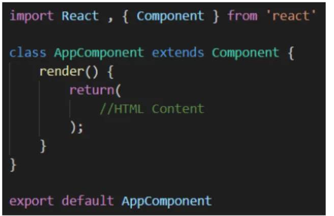
React Components
Components (example in Fig 2.16) allow the separation of UI sections as indepen-dent and reusable pieces [17]. A Stateful component’s (Fig2.17) internal state that can be accessed through this.state or changed with the setState() API provided by the component class. A component can also receive data as input, to which it has access through this.props.
Figure 2.16 – A React Component implements the render() method, where the HTML template is defined.
Figure 2.17 – Stateful Component’s internal state definition.
Component Lifecycle
A component’s lifecycle consists of methods run in a set order (Fig 2.18). Those methods can be accessed and overridden to run a section of code in a specific moment of the life cycle. There are three moments in a component’s life cycle [17]:
1. Mounting: These methods are run when a component is instantiated and inserted into the DOM.
(a) constructor(): Internal state and other variables initialization;
(b) componentWillMount(): Method called before the render() method; (c) render(): This is the main React method, where a React element is
created based on the internal state or incoming input (from props); (d) componentDidMount(): Similar to componentWillMount, but called
after the render() method.
2. Updating: When props or internal state change, the component is re-rendered, calling these methods.
(a) componentWillReceiveProps(): Invoked when an already mounted component is going to receive new input from props. In this method, this.props refers to the current props, and nextProps refers to the new incoming props;
(b) shouldComponentUpdate(): This method evaluates if the compo-nent’s output is going to change after receiving the new data, re-rendering if true is returned;
(c) componentWillUpdate(): Confirming that the component is going to update, this method is called right before the render() method;
(d) render(): Same render() method explained for the Mounting operations; (e) componentDidUpdate(): Run after re-rendering the component.
3. Unmounting: Consists of only one method, called when the component is removed from the DOM.
(a) componentWillUnmount(): Cleanup operations before the compo-nent is removed from the DOM.
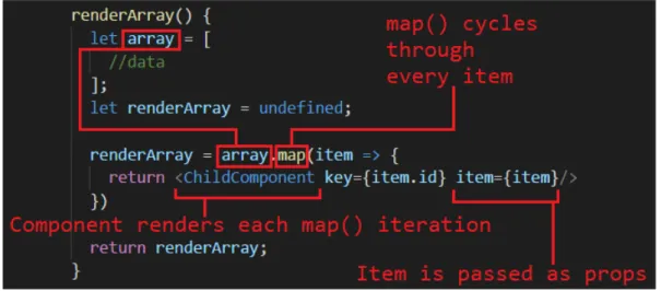
Rendering Lists with React
The modularity that React offers with its components allows an easy way to render lists. Considering a parent component that contains an array in its state, it can render the list by initializing a child component for each element (Fig 2.19). Using the map() API provided by JavaScript, each element will return a React component using its data (fig 2.20).
Figure 2.19 – Rendering lists with React illustration.
2.2.3
Bootstrap
Bootstrap is a Framework developed by Twitter that uses HTML, CSS and JavaScript to help create responsive web pages.
Based on a Flexbox grid system, Bootstrap implements a 12 column layout with mul-tiple default size behaviours (using CSS media queries) based on viewport width. An HTML element can be assigned Bootstrap properties by providing the class name with the prefix .col-. Based on what description follows the prefix (Fig 2.21), the element will have a minimum width (breakpoint). When the available window size does not allow it to have that minimum value, the element is not displayed.
Figure 2.21 – Bootstrap’s Grid System Table [6].
Fig 2.22(a) illustrates how an HTML document should be structured using Boot-strap, and Fig 2.22(b) shows how that structure is rendered.
A container (red color in the images) wraps every Bootstrap element. The first elements defined inside a container are rows (yellow in the images), which contain up to 12 columns. The elements placed inside rows are columns (green color for first row and blue for the second one), which occupy a percentage of the parent’s size based on the number of columns defined inside its row, so that the row’s space is filled.
(a) Bootstrap HTML arrange-ment and CSS classes.
(b) Bootstrap Result Render. Figure 2.22 – Bootstrap Example [6]
React Bootstrap
Using React, Bootstrap’s use becomes easier due to NPM (subsection2.4.1) modules that allow the use of Bootstrap components built with React. This provides a simpler syntax for Bootstrap elements definition (comparison in Fig 2.23) as well as pre-built components such as progress bars, navbars and many others. Although there is a module for Bootstrap version 3 (React-Bootstrap) and one for version 4 (Reactstrap), the latter is still under-supported online and has some bugs yet (at the time of writing).
(a) Normal Bootstrap. (b) Bootstrap React components. Figure 2.23 – React Bootstrap Example
2.3
Software Application Architectures
Defining a software application architecture lays the foundation for building a scal-able, reliscal-able, available and manageable web application [27].
A suitable application architecture is specified based on the interaction between all its components (packages, databases and middleware), ensuring that the data is securely encapsulated and accessible on demand, allowing the web application to work as intended. In the next sections, the two application architectures considered during the course of this project will be reviewed.
2.3.1
Model-View-Controller (MVC)
MVC divides the application into three components (Fig 2.24), allowing efficient code recycling and the development of each part in parallel and independently.
• Model: This component deals with the application’s logic related to handling data from its state. The Model is responsible for responding to requests for data, or to change the information on a database [23]. All its functionalities are available for the Controller to call, on demand.
• View: The View is responsible for all the logic in the User Interface, col-lecting information from the Model and presenting it to the user, therefore allowing the connection between the user and the data stored on the database. Considering the MVC architecture to be implemented in the MatUTAD web application, this component will correspond to the Front-End development of the project.
• Controller: User inputs generate actions, received by the Controller, which is responsible for calling the Model functions available in order to interact with the application’s state. The Controller can also implement some logic in order to treat the data being sent to the View.
Although the Front-End part of a web application is encapsulated within the View component of the MVC architecture, the Front-End itself is a standalone application, which can be also have an internal MVC structure.
With the implementation of an MVC architecture on the client, some problems arise, mainly due to the dependency between UI state (information related to the DOM components) and Application state (the information coming from the server side of the web application, stored in the Front-End for JavaScript interaction), which doesn’t allow the Front-End to scale [29] [15].
2.3.2
Flux
The solution for the problem stated in section 2.3.1 was presented by the Facebook Developers, with the introduction of the Flux architecture.
Since the bidirectional dependency between the Model and the View could trigger infinite loops, as well as make the code’s debugging very difficult as the application
grows, they proposed a unidirectional architecture for the Front-End development, allowing a simple line of thought for each action to lead to the state change it triggers, in a predictable data flow. A Flux architecture is composed by Actions, a single Dispatcher, Stores and Views [15] [14] [21].
Figure 2.25 – Flux Architecture Diagram [40].
Actions
When a user interacts with the interface (clicking a button for example) or the server responds to a request from the Front-End, an Action is called, which describes the correspondent interaction.
It is recommended that the application contains a Constants file, which keeps a list of all the Actions it is capable of handling, helping with organization and giving an overview of every possible interaction with the application.
Dispatcher
The Dispatcher is the central unit of a Flux architecture, only existing one per application.
This component holds a list of callbacks from every Store that registers to it, calling the correspondent one according to the Action being dispatched.
Whenever an Action occurs, a method exposed by the Dispatcher is used to trigger a dispatch, which generates a payload containing the action type and the data being sent (Fig 2.26).
Figure 2.26 – Flux Dispatch Example.
That payload is then broadcast to every registered Store, allowing it to update itself based on the data contained in the payload.
Stores
Stores hold the application’s state, perform logic operations to handle it, and expose
a data retrieval method so that the View can update itself based on the Store’s state. A Store extends NodeJS’ (a JavaScript runtime built on Chrome’s V8 JavaScript engine) Event Emitter class, which will allow the Store to listen to dispatches from the central Dispatcher, as well as broadcast events (when a callback is completed) to the registered Views. Callbacks are registered with the Dispatcher, allowing for a specific logic to be implemented when a dispatch occurs.
Since a single dispatch can update many Stores, the callback run order can be manipulated by using the waitFor API provided by the Dispatcher. Using that method, the Store can choose to run the callback only when another Store emits its changes.
View
The View is the component that presents the data from Stores, accessing it through the data retrieval method exposed by the corresponding Store.
A View component registers to a Store by subscribing to its change events, so that whenever a Store’s callback is finished, every subscribed View will be notified to update itself, re-rendering according to the new data.
Flow of Data
With all the Flux components explained, it’s easier to have an overview of the data flow for every action, occurring in the following pattern (Fig 2.25):
1. An Action triggers a dispatch;
2. The Dispatcher generates a payload with an action type and data;
3. A list of registered callbacks is checked to determine which Stores should re-ceive the payload;
4. The Dispatcher sends the payload to all the registered Stores;
5. A Store updates the internal state by running the callback logic for processing the data in the payload;
6. After processing the data, the Store emits a change event, notifying every View component subscribed to it that there’s new data;
7. The View re-renders the UI, dynamically updating its content.
2.4
Other Relevant Technologies
While the main technologies were explained in the previous sections, there are some other technologies that should be considered in Front-End development, some as core functionalities for an application and others as a tool to help to help with the project, which will be reviewed in this section.
2.4.1
Node Package Manager (NPM)
NPM allows the reutilization and redistribution of code (packages or modules) which solves particular problems, thus abstracting a developer from certain tasks that al-ready have a solution. The NPM database contains almost half a million modules. As the application uses more and more modules, this tool also helps with their man-agement by organizing all the project’s dependencies in a single ’package.json’ file (Fig 2.27). That way, it becomes easier to have an overview of the packages being used for the development, as well as installing and updating them at any time [39].
Figure 2.27 – NPM Dependencies Example.
2.4.2
Hypertext Transfer Protocol (HTTP)
HTTP is a standard stateless protocol that allows the communication in a Client/Server model (where a web server provides resources and services to its clients) through the World Wide Web.
An HTTP communication pattern requires a Transmission Control Protocol (TCP) connection, which uses port 80 as the default port for HTTP.
A web client submits an HTTP request message consisting of [18]:
• A method regarding the action to be performed by the resource, such as GET for data retrieval, POST for resource update, PUT for new data to be stored, and DELETE for a resource delete operation;
• A Uniform Resource Identifier (URI), which identifies a resource by charac-teristics such as a name or location;
• The protocol version in use, mostly HTTP/1.1, although HTTP/2 has been standardized in 2015 but still not globally supported.
The resource is then responsible for answering with an HTTP response message after processing the request. The response message contains a Status-Line, composed by a Status Code and the corresponding textual phrase, which can be [18]:
1xx Informational
2xx Success
3xx Redirection 4xx Client Error 5xx Server Error
Both the Request and Response have a Header, which contain additional informa-tion to the message, and a Body (opinforma-tional), that contains encapsulated informainforma-tion such as forms coming from the Front-End or database information coming from the Back-End (example of an HTTP request and response in Fig 2.28).
Hypertext Transfer Protocol Secure (HTTPS)
HTTP stores information in a text format, which can be intercepted and accessed. In order to make the HTTP protocol more secure, HTTPS establishes a connec-tion (port 443 instead of 80 from HTTP) using an encrypconnec-tion procotol, Secure Sockets Layer (SSL) or Transport Layer Security (TLS), which both use an asym-mectric Public Key Infrastructure (PKI). When an HTTPS connection is initiated, the website sends its encryption certificate, which contains the public key used in the encryption needed to establish the secure session [22].
Figure 2.28 – HTTP Structure [36].
2.4.3
JavaScript Object Notation (JSON)
Information transfered between a client and a server can often times be very complex, therefore imposing the need for a structure of data that can be easily represented and parsed.
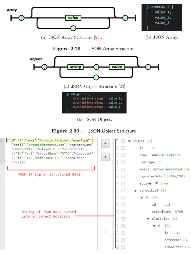
JSON is a popular data format for exchanging information, which consists of
con-verting it into a well structured text format that can be sent over the Internet and parsed at an end-point for easy manipulation (Fig2.31) [25]. A JSON Value can be an object (Fig2.30), array (Fig 2.29), number, string, true, false, or null.
(a) JSON Array Structure [25]. (b) JSON Array. Figure 2.29 – JSON Array Structure
(a) JSON Object Structure [25]
(b) JSON Object.
Figure 2.30 – JSON Object Structure
2.4.4
Asynchronous JavaScript and XML (AJAX)
As mentioned before, JavaScript allows dynamic changes to a web page, but data requested from servers would always need the page to be reloaded, slowing down the user experience.
AJAX [19] is a concept that makes use of the XMLHttpRequest API (an object used to interact with servers through HTTP requests) to send an HTTP request with data encoded in a text format, and handling the corresponding response (Fig 2.32). This process allows an exchange of data between Client and Server without the need for a page reload, further enhancing the application’s speed. Although the X in AJAX refers to XML, any text format encoding can be used, with JSON being the most popular due to its simple syntax and reduced overhead [30]
Figure 2.32 – AJAX communication structure [28].
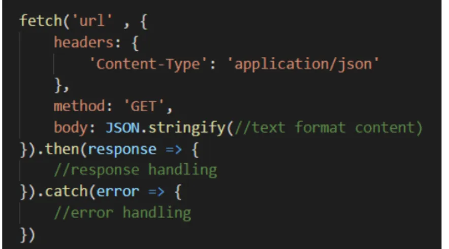
Fetch API
While AJAX was introduced using XMLHttpRequest (XHR), this object’s imple-mentation requires some boilerplate code (a lot of mandatory lines of code for min-imal tasks implementation), making its use not optmin-imal. Using the jQuery library provides a simpler syntax for XHR, but at the cost of using a heavy library.
Introduced with ES6, the Fetch API replaces XMLHttpRequest in an AJAX re-quest by providing an interface with simpler syntax and powerful features [32]. This API uses JavaScript’s Promises (explained previously in section 2.1.4) to handle a response or an error [58].
Fig 2.33 shows an implementation of the Fetch API. The first argument fetch() uses is mandatory, a URL for the server’s resource to be accessed. A second optional argument can be specified, defining HTTP request parameters such as the headers, method and body. Since this API uses Promises to perform the asynchronous re-quest, it requires the specification of what it should do when the request is successful (using then()) and when it fails (using catch).
3
Conception
Starting this project’s conception, it was necessary to define and organize the sys-tem’s design, creating a blueprint for the current and future developers to follow pre-determined requirements.
This chapter will provide an overview of the matUTAD application, system require-ments, followed by their organization and structuring in diagrams developed along with the Back-End project, part of another Master Thesis [5].
3.1
An overview of matUTAD
The matUTAD game consists of twenty five questions to be answered within thirty minutes. Each question contains four statements to be assessed as true or false. The new matUTAD platform should support four game modes:
• Trial: A demonstration game with pre-determined questions;
• Training: Students can access their accounts to test their skills in an unranked game, where they can specify which question modules to include;
• Evaluation: This game type is created by teachers to assess their student’s current levels;
• Competition: The main game mode for MatUTAD where students from many schools compete.
Although the core purpose of matUTAD is to provide an online mathematics game platform for students from seventh through twelfth grades, the application should also supports management functionalities available to different users.
Users and Functionalities
The matUTAD platform provides functionalities for four user types, divided as fol-lows:
• Guests: Unregistered visitors can access the trial game and check the Com-petitions Rankings;
• Students: Permanent access to Training mode. Evaluations and Competi-tions are available to students registered in these modes by their teachers; • Teachers: Responsible for managing their own students and registering them
for evaluations or competitions. Teachers can also create evaluations, but competitions creation must be approved by an administrator;
• Administrators: Control over the application’s users and games.
Teachers and Administrators can also have access to two optional functionalities (to be defined by an Administrator):
• Question Management: Control over questions parameters stored in the database;
• Start Competitions: A competition can only be accessed and started by a user with this permission.
3.2
Requirements Gathering
For this project, the requirements gathering followed an Agile Modeling standard, the User Stories, which consist of a very high-level definition of a feature to be implemented, providing a simple sentence that describes it, as well as allowing an overview of the tasks to be distributed by the project’s team [2].
3.2.1
User Stories
Considering the simplicity that a User Story has to provide when describing a re-quirement, it should be written in the pattern described in Fig 3.1. A User Story’s sentence should answer three questions:
• Who?: Describes the subject that is associated with the task; • What?: Describes the task to be implemented;
• Why?: Refers the task’s achievement (optional).
Figure 3.1 – User Story text template.
In this project, the User Stories were written (Subsection 3.2.2) and later trans-formed into tables (Subsection3.2.3, Tables3.1,3.2,3.3,3.4,3.5) in order to organize them in the ‘Who?, What?, Why?’ pattern, and presenting additional information for each case.
3.2.2
User Stories for matUTAD
Guest User
• As a Guest I can access/start the trial game mode;
– As a Guest I need to specify the school year for the game so I can start
the trial game mode.
• As a Guest I can check the Competitions Ranking.
Registered User (Student, Teacher, Admin)
• As a registered user I need to login using a username and password so I can access private content.
Student
• As a Student I can access the games page;
• As a Student I can play an Evaluation or Competition game in which I’m registered;
• As a Student I can play the training game mode;
– As a Student I can specify the question modules so that I can filter the
questions for the training game mode.
• As a Student I can check the rankings for Evaluation and Competition game modes.
Teacher
• As a Teacher I can register new Students;
– As a Teacher I need to specify the Student’s parameters (email, name,
school, class, current year) so that I can register new Students.
• As a Teacher I can edit the Student’s parameters (email, name, school, class, current year, active state);
• As a Teacher I can register students for Evaluations and Competitions; • As a Teacher I can check the Rankings for Evaluations and Competitions; • As a Teacher I can see a list of my Students;
• As a Teacher I can start/end an Evaluation/Competition.
Administrator
• As an Admin I can register Teachers;
– As an Admin I need to specify the Teacher’s parameters (active state,
email, name, permission to manage questions, permission to start com-petitions, school, class) so that I can register new Teachers.
• As an Admin I can edit User’s parameters; • As an Admin I can create Competitions;
– As an Admin I need to specify the Competitions details in order to create
new Competitions.
• As an Admin I can start Competitions; • As an Admin I can see a list of users.
Users with Question Management permissions
• As a Question Manager I can see a list of questions; • As a Question Manager I can edit questions details; • As a Question Manager I can create new questions;
– As a Question Manager I need to specify the question’s details (question
text, active state, difficulty, school year, question module, author, image). • As a Question Manager I can create Question Modules.
3.2.3
User Stories Table Format
Who? What? Why? Additional Info
Guest
Access trial game
— Requires specification of school year
Check competi-tions ranking
— Restricted to competitions
marked as visible by an Admin
Table 3.1 – Guest user stories table
Who? What? Why? Additional Info
Student
Log In Access
restricted content
Requires username and password
Access games page
— —
Play a game — Training games allow the specifi-cation of question modules. Eval-uations and Competitions are only accessible to students regis-tered to them
Check rankings — Evaluations and Competitions
Who? What? Why? Additional Info Question Check questions list — — Manager Edit question details — — Create new questions
— Requires specification of: ques-tion text, active state, difficulty, school year, question module, au-thor and image
Create question modules
— —
Table 3.3 – Question Manager permissions user stories table
Who? What? Why? Additional Info
Teacher
Log In Access
restricted content
Requires username and password
Register new students
— Requires specification of: email, name, school, class and current school year
Edit student’s parameters
— Available parameters: email,
name, school, class, current school year and active state Register
Stu-dents for
Eval-uations or
Competitions
— —
Check students list
— Only displays its own students
Start
Eval-uations or
Competitions
— Starting a competition requires ‘Start Competition’ permissions
Who? What? Why? Additional Info
Admin
Log In Access
restricted content
Requires username and password
Register new teachers
— Requires specification of: active state, email, name, school, class and definition of ‘Question Man-agement’ and ‘Start Competi-tions’ permissions
Edit users pa-rameters
— Available parameters depending
on user type Create
Competi-tions
— Requires specification of competi-tion’s details (school year, name, date, duration, paired students, number of questions and number of game attempts)
Start Competi-tions
— Requires ‘Start Competitions’
permissions
Check users list — —
3.3
Use Case Diagrams
The Use Case diagrams consist of a graphic interpretation of the User Stories, pro-viding an overview of the system’s users and the functionalities available to them [10]. Functionalities triggered after a pre-defined time (loggout for inactivity for example) can be associated to a Time user.
These diagrams are built on the behavioral Unified Modeling Language (UML) stan-dard, and have the structure presented in Fig 3.2. An ‘Extends’ arrow specifies optional functionalities associated with the main action, while an ‘Includes’ one defines a mandatory tasks.
Figure 3.2 – Use Case diagram example.
3.3.1
Use Case Diagrams for matUTAD
Considering the User Stories presented in Subsection 3.2.2, the Use Case diagrams were created with the specified functionalities, starting with the use cases for a Guest User, who should only have the ability to play the trial game mode and access the Competitions Rankings available (Fig 3.3).
Figure 3.3 – Guest use cases for matUTAD.
As for an Administrator, the use cases represent its control over most of the applica-tion’s functionalities (Fig3.4), including users related actions (check users accounts, add and edit) and games related ones (creating a competition and starting it).
Regarding Students (Fig 3.5), their functionalities are mainly related to the actual playing of the game, either Training mode or an Evaluation/Competition to which it is registered.
Figure 3.5 – Student use cases for matUTAD.
The use cases created for Teachers were divided into two diagrams for a better visibility. Fig 3.6 includes functionalities related to games, while Fig 3.7 specifies the actions related to managing their Students.
Figure 3.7 – Teacher use cases for matUTAD (Part 2).
The last use cases created refer to the functionalities a user with Question Manage-ment permissions has access to (Fig 3.8).
3.4
Entity and Relationships Diagram
Storing data in a database is key to having persistent, organized information in an application. A relational database consists in groups of tables that organize objects of the same type (rows), and each object contains fields of related data (columns). The Fig 3.9 illustrates the structure of a table and its elements.
Figure 3.9 – Relational database table example.
Since tables can be related, an Entity and Relationships diagram allows the graphical presentation of the database, connecting related tables and presenting the attributes for each one [41]. Each table object must also have a unique identifier (ID), which is called a Primary Key when presented within the object, but can also serve as a way to specify which objects of two tables are related, becoming a Foreign
Key (Fig 3.10). The Entity and Relationships diagram for matUTAD is presented in Subsection 3.4.1, Fig 3.11, and the respective database was implemented in the Back-End project [5].
3.4.1
Entity and Relationship Diagram for matUTAD
3.5
Classes Diagram
Considering the implementation of Object Oriented Programming for the Back-End using Java, it was necessary to develop the Classes Diagram, which would allow the structuring of all the classes, respective attributes and methods, as well as the relationship between all of them [10]. A Classes Diagram is designed as pre-sented in image 3.12, and can also define cardinality between relationships, like the E-R diagram, as well as defining class extension.
Figure 3.12 – Classes diagram example.
In Subsection 3.5.1, Fig3.13 contains the Classes diagram conceived for matUTAD. Regarding the extension of the User class, there was only the need for a Student class, because although there are other user types, they don’t have any data associated besides the one already included in User.
3.5.1
Classes Diagram for matUTAD
3.6
Server Requests
Having the base diagrams developed, there was a need to define the parameters for the Front-End and Back-End communication. In order to do so, a document was developed with three items for each interaction:
• Description: Small description of communication;
• Request: Defines the HTTP request method and optional parameters sent in its Body (JSON Format).
• Response: Defines the status code and the optional response parameters, also sent in the Body (JSON Format).
3.6.1
Server Requests for matUTAD
News Related Requests
Considering that the Home page displays the news related to Basic School and Highschool, as well as press quotes about matUTAD, Fig 3.14 provides the server request parameters for their retrieval.
Login Related Requests
When a registered user logs into its account, the request follows the pattern pre-sented in Fig 3.15. In order for a better performance of the application, logging in successfully also returns data about the user’s permissions (question management and start competitions) in order to provide information about which functionalities are available, as well as a list of associated schools and respective classes.
Logging out is also available, as displayed in Fig3.16.
Figure 3.16 – Logout Server Request.
User Management Requests
Teachers and Administrators have access to a list of users (students and all users respectively), which is requested and responded to as depicted in Fig 3.17.
Considering the creation of a new user, since each user type contains different pa-rameters (administrators don’t have schools, teachers can have multiple schools and classes, students only have one school and one class etc.), each one has a different method, as presented in Fig3.18,3.19 and 3.20.
Figure 3.18 – Add Administrator Server Request.
![Figure 2.2 – Left: The markup structure of HTML; Right: The final result [54].](https://thumb-eu.123doks.com/thumbv2/123dok_br/15942592.1096482/34.892.154.648.836.1028/figure-left-markup-structure-html-right-final-result.webp)
![Figure 2.3 – An example of selectors and respective properties defined [33].](https://thumb-eu.123doks.com/thumbv2/123dok_br/15942592.1096482/35.892.231.735.601.828/figure-example-selectors-respective-properties-defined.webp)
![Figure 2.18 – React Component Life Cycle [8].](https://thumb-eu.123doks.com/thumbv2/123dok_br/15942592.1096482/51.892.185.785.635.923/figure-react-component-life-cycle.webp)
![Figure 2.25 – Flux Architecture Diagram [40].](https://thumb-eu.123doks.com/thumbv2/123dok_br/15942592.1096482/57.892.180.794.311.550/figure-flux-architecture-diagram.webp)
![Figure 2.32 – AJAX communication structure [28].](https://thumb-eu.123doks.com/thumbv2/123dok_br/15942592.1096482/64.892.165.641.532.835/figure-ajax-communication-structure.webp)